Table of Contents
Advertisement
Quick Links
Advertisement
Table of Contents

Subscribe to Our Youtube Channel
Related Manuals for UFactory XARM


Summary of Contents for UFactory XARM
-
Page 2: Table Of Contents
Table 1. General Presentation ......................4 1.1. Gripper Introduction....................4 1.2. Object Picking .......................5 1.3. Setup and Control ......................5 1.4. Safety ..........................5 1.4.1. Warning .......................6 1.4.2. Risk Assessment and Final Application ............7 1.4.3. Intended Use ......................8 2. Installation ..........................9 2.1. Scope of Delivery ......................9 2.1.1. - Page 3 3.1. Use xArm Studio to Control BIO Gripper ............14 3.2. Use Python-SDK to Control BIO Gripper ............17 3.3. Use Modbus-TCP Communication Protocol to Control BIO Gripper ..17 3.3.1. Modbus-TCP Communication Format ............17 3.3.2. Read BIO Gripper Register ................18 3.3.3.
-
Page 4: General Presentation
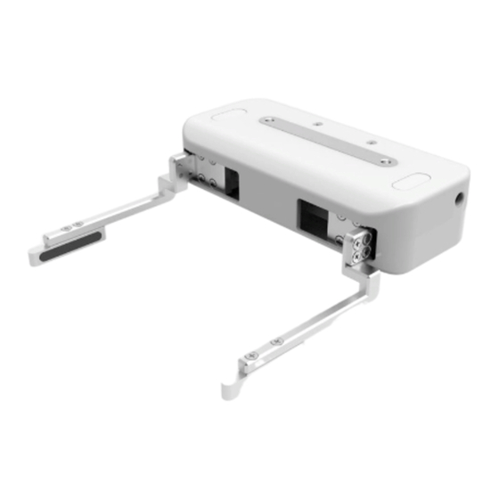
1. General Presentation 1.1. Gripper Introduction BIO Gripper The xArm BIO Gripper is a gripper designed for liquid handling. It provides fast deployment paired with simple customization and easy programming. The gripper is a multifunctional tool, boasting customized fingertips to provide gripping flexibility. -
Page 5: Object Picking
(3) Highly integrated with xArm As a safe and stable integration, the xArm BIO Gripper is highly compatible with xArm, controlled directly by the IO port at the end of the machine without external cables and connectors. 1.2. Object Picking The fingers of the BIO Gripper adopt a parallel grasp, Figures are shown below. -
Page 6: Warning
The operator must have read and understood all of the instructions in the following manual before handling the BIO Gripper. Caution The term "operator" refers to anyone responsible for any of the following operations on the BIO Gripper: ● Installation ●... -
Page 7: Risk Assessment And Final Application
Warning ● The Gripper needs to be properly secured before operating the robot. ● Do not install or operate a Gripper that is damaged or lacking parts. ● Never supply the Gripper with an alternative current (AC) source. ● Make sure all cord sets are always secured at both ends,Gripper end & Robot end ●... -
Page 8: Intended Use
The unit may be used only within the range of its technical data. Any other use of the product is deemed improper and unintended use. UFACTORY will not be liable for any damages resulting from any improper or unintended use. -
Page 9: Installation
2. Installation The following subsections will guide you through the installation and general setup of BIO Gripper. (1) The Scope of Delivery section (2) The Mechanical Installation section (3) The Electrical Setup section Warning Before installing: Read and understand the safety instructions related to the BIO Gripper. Verify your package according to the Scope of delivery and your order info. -
Page 10: General Kit
2.1.1. General Kit A Gripper Kit generally includes these items: BIO Gripper BIO Gripper adapter plate Cross countersunk head screws M6*8 (4) Cross countersunk head screws M6*10 (2) 2.2. Mechanical Installation BIO Gripper installation steps (as shown below): (1) Fix the BIO Gripper adapter plate to the tool flange of the robotic arm with screws. - Page 11 (3) Connect the robotic arm and the Gripper with the gripper connection cable. Note: 1. When wiring the gripper connection cable, be sure to power off the robotic arm, the emergency stop button is in the pressed state and the power indicator of the robotic arm is off, so as to avoid robotic arm failure caused by hot plugging;...
-
Page 12: Electrical Setup
2.3. Electrical Setup Power and communication are established with the BIO Gripper via a single gripper connection cable. The gripper connection cable provides a 24V power supply to the Gripper and enables serial RS485 communication to the robot control box. Warning Power must be off before connecting the Gripper and the robotic arm via the gripper connection cable. - Page 13 Pin sequence Function 485-A 485-B Digital Input 0 Digital Input 1 Digital Output 0 Digital Output 1 No Connect No Connect...
-
Page 14: Control
3. Control 3.1. Use xArm Studio to Control BIO Gripper 1. Set up BIO Gripper Enter [Settings]-[End Effector] ⚫ Select the end effector: xArm BIO Gripper 1. The opening and closing speed of the gripper can be adjusted. 2. The self-collision prevention model of the gripper can be turned on by clicking the button. - Page 15 2. Control BIO Gripper Control the BIO gripper in the live control ⚫ Control Method: 1) Click the [Enable] button to enable the BIO gripper; 2) By clicking the [Open]/[Close] button, you can control the opening and closing of the gripper.
- Page 16 Control the BIO gripper through Blockly ⚫ BIO_Gripper.Blockly The role of this program: execute this program to control the gripper to pick the target object at the specified position, and then place the target object at the target position.
-
Page 17: Use Python-Sdk To Control Bio Gripper
3.3. Use Modbus-TCP Communication Protocol to Control BIO Gripper This section mainly explains how to control the BIO Gripper by using the Modbus-TCP protocol through xArm control box. Modbus-TCP Communication Format 3.3.1. Modbus-TCP: Modbus protocol is an application layer message transmission protocol, including... -
Page 18: Read Bio Gripper Register
three message types: ASCII, RTU, and TCP. The standard Modbus protocol physical layer interface includes RS232, RS422, RS485 and Ethernet interfaces, and adopts master / slave communication. Modbus TCP Communication Process: 1. Establish a TCP connection 2. Prepare Modbus messages 3. - Page 19 Read Register Request Transaction Identifier 2 Bytes 0x0001 Protocol Identifier 2 Bytes 0x0002 MBTP Header Length 2 Bytes 6+N*x2 Unit Identifier 1 Byte 0x7C Internal Use Internal Use 1 Byte 0x09 Slave ID (Gripper) 1 Byte 0x08 Function Code 1 Byte 0x03 Modbus RTU Data Register Starting Address...
- Page 20 Error status: 0x000B An error occurs: Get Gripper Error all other return values indicate an 0x000F 2 Bytes Register error(except 0) No error occurred: 0x0000 3.3.2.2. Example 1. Get the BIO Gripper status Get the BIO Gripper status Request Transaction Identifier 2 Bytes 0x0001 Protocol Identifier...
-
Page 21: Write Bio Gripper Register
2. Get the BIO Gripper Error Get the BIO Gripper Error Request Transaction Identifier 2 Bytes 0x0001 Protocol Identifier 2 Bytes 0x0002 MBTP Header Length 2 Bytes 0x08 Unit Identifier 1 Byte 0x7C Internal Use Internal Use 1 Byte 0x09 Slave ID (Gripper) 1 Byte 0x08... - Page 22 Internal Use Internal Use 1 Byte 0x09 Slave ID (Gripper) 1 Byte 0x08 Function Code 1 Byte 0x10 Register Starting 2 Bytes Address Modbus RTU Data Quantity of Registers Address 2 Bytes Byte Count 1 Byte N*x2 Registers Value N*x2 Value Response Bytes...
- Page 23 3.3.3.2. Example 1. Enable/Disable BIO Gripper Enable/Disable BIO Gripper Request Transaction Identifier 2 Bytes 0x0001 Protocol Identifier 2 Bytes 0x0002 MBTP Header Length 2 Bytes 0x000B Unit Identifier 1 Byte 0x7C Internal Use Internal Use 1 Byte 0x09 Slave ID (Gripper) 1 Byte 0x08 Function Code...
- Page 24 Slave ID (Gripper) 1 Byte 0x08 Function Code 1 Byte 0x10 Register Starting Address 2 Bytes 0x0303 Modbus RTU Data Quantity of Registers 2 Bytes 0x0001 Byte Count 1 Byte 0x02 Registers 2 Bytes 0x05DC Value(1500r/min) Response Transaction Identifier 2 Bytes 0x0001 Protocol Identifier 2 Bytes...
- Page 25 Response Transaction Identifier 2 Bytes 0x0001 Protocol Identifier 2 Bytes 0x0002 MBTP Header Length 2 Bytes 0x0009 Unit Identifier 1 Byte 0x7C Status Value 1 Byte 0x00 Internal Use Internal Use 1 Byte 0x09 Slave ID 1 Byte 0x08 Function Code 1 Byte 0x10 Modbus RTU Data...
-
Page 26: Bio Gripper Control Process
BIO Gripper Control Process 3.3.4. The complete process of controlling the motion of the BIO Gripper is as follows: (1) Enable the Gripper 0x00, 0x01, 0x00, 0x02, 0x00, 0x0B, 0x7C, 0x09, 0x08, 0x10, 0x01, 0x00, 0x00, 0x01, 0x02, 0x00, 0x01 (2) Open the Gripper 0x00, 0x01, 0x00, 0x02, 0x00, 0x0D, 0x7C, 0x09, 0x08, 0x10, 0x07, 0x00, 0x00, 0x02, 0x04, 0x00, 0x00, 0x00, 0x82... -
Page 27: Read Bio Gripper Register
0x10. In this article, data analysis is big-endian analysis. Read BIO Gripper Register 3.4.2. Read Register Request Slave ID (Gripper) 1 Byte 0x08 Function Code 1 Byte 0x03 Modbus RTU Data Register Starting Address 2 Bytes Address Quantity of Register 2 Bytes Modbus CRC16 2 Bytes... -
Page 28: Write Bio Gripper Register
No error occurred: 0x0000 Write BIO Gripper Register 3.4.3. Write Register Request Slave ID (Gripper) 1 Byte 0x08 Function Code 1 Byte 0x10 Register Starting 2 Bytes Address Modbus RTU Quantity of Register 2 Bytes Address Data Byte Count 1 Byte N*x2 Registers Value N*x2... -
Page 29: Modbus Rtu Example
Clear Position Error Register 0x000F 2 Bytes 0x0000 Modbus RTU Example 3.4.4. This section demonstrates the example given in the Control Logic section when programmed using the Modbus RTU protocol. Step1:Enable BIO Gripper Enable BIO Gripper Request Slave ID (Gripper) 1 Byte 0x08 Function Code... - Page 30 Registers Value(1500r/min) 2 Bytes 0x05DC Modbus CRC16 2 Bytes 0xFDFA Response Slave ID 1 Byte 0x08 Function Code 1 Byte 0x10 Modbus RTU Data Register Starting Address 2 Bytes 0x0303 Quantity of Registers 2 Bytes 0x0001 Modbus CRC16 2 Bytes 0xF114 Step3:Open BIO Gripper Open BIO Gripper...
- Page 31 Slave ID 1 Byte 0x08 Function Code 1 Byte 0x03 Byte Count 1 Byte 0x02 Modbus RTU Data Registers Value 2 Bytes 0x0000 (Robotic arm is in stop statu) Modbus CRC16 2 Bytes 0x6445 Step4:Close BIO Gripper Close BIO Gripper Request Slave ID (Gripper) 1 Byte...
- Page 32 Function Code 1 Byte 0x03 Byte Count 1 Byte 0x02 Registers Value 2 Bytes 0x0000 (Robotic arm is in stop statu) Modbus CRC16 2 Bytes 0x6445...
-
Page 33: Gripper Error Code & Error Handling
1. Re-powering the robotic arm via the emergency stop button on the control box. 2. Enable robotic arm. a. xArm Studio enable mode: Click the guide button of the error pop-up window or the ‘STOP’ red button in the upper right corner. b. xArm-Python-SDK enable mode: Refer to Alarm Handling Mode. - Page 34 Error Handling: When designing the robotic arm motion path with the Python library, if the robotic arm error (see Appendix for Alarm information) occurs, then it needs to be cleared manually. After clearing the error, the robotic arm should be motion enabled.
-
Page 35: Bio Gripper Technical Specifications
5. BIO Gripper Technical Specifications BIO Gripper Rated Supply Voltage 24V DC Absolute Maximum Supply Voltage 28V DC Static Power Consumption 0.96W (Minimum Power Consumption) Peak Current 1.5A Weight 760g Maximum Gripping Force Stroke 70-150mm Communication Mode RS-485 Communication Protocol Modbus RTU Programmable Gripping Specification Speed Control... -
Page 36: After-Sales Service
(1) Contact UFACTORY technical support (support@ufactory.cc) to confirm whether the product needs to repair and which part should be send back to UFACTORY. (2) After bill of lading on UPS, we will send the invoice and label to you by mail. You need to make an appointment with the local UPS and then send the product to us.
Need help?
Do you have a question about the XARM and is the answer not in the manual?
Questions and answers