
Related Manuals for Rockwell Automation Allen-Bradley ArmorBlock 5000 Series


Summary of Contents for Rockwell Automation Allen-Bradley ArmorBlock 5000 Series
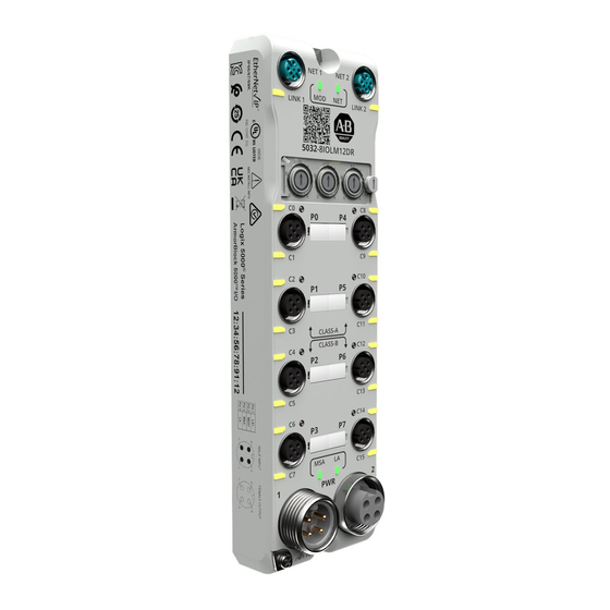
- Page 1 ArmorBlock 5000 8-channel IO-Link Master Module Catalog Numbers 5032-8IOLM12DR, 5032-8IOLM12M12LDR, 5032-8IOLM12P5DR User Manual Original Instructions...
- Page 2 If this equipment is used in a manner not specified by the manufacturer, the protection provided by the equipment may be impaired. In no event will Rockwell Automation, Inc. be responsible or liable for indirect or consequential damages resulting from the use or application of this equipment.
-
Page 3: Table Of Contents
Chatter Detection ............24 Rockwell Automation Publication 5032-UM001A-EN-P - April 2023... - Page 4 Module Info View ............49 Rockwell Automation Publication 5032-UM001A-EN-P - April 2023...
- Page 5 Module Diagnostic Webpages ..........87 Rockwell Automation Publication 5032-UM001A-EN-P - April 2023...
- Page 6 ............... 119 Rockwell Automation Publication 5032-UM001A-EN-P - April 2023...
-
Page 7: Preface
Industrial Automation Wiring and Grounding Guidelines, publication 1770-4.1 Provides general guidelines for installing a Rockwell Automation industrial system. Product Certifications website, rok.auto/certifications Provides declarations of conformity, certificates, and other certification details. - Page 8 Preface Notes: Rockwell Automation Publication 5032-UM001A-EN-P - April 2023...
-
Page 9: Introduction
ADC (Data Storage) modes. • Provides recovery of configuration data for IO-Link devices in both ADC and non-ADC (Data Storage) modes by restoring the device configuration that is saved in a project file to the devices. Rockwell Automation Publication 5032-UM001A-EN-P - April 2023... -
Page 10: Controller And Software Compatibility
For more information on the controllers, see the following publications: • CompactLogix™ 5380 and Compact GuardLogix® 5380 Controllers User Manual, publication 5069-UM001. • CompactLogix 5480 Controllers User Manual, publication 5069-UM002. • ControlLogix® 5580 and GuardLogix 5580 Controllers User Manual, publication 1756-UM543. Rockwell Automation Publication 5032-UM001A-EN-P - April 2023... -
Page 11: Module Overview
5032-8IOLM12M12LDR. The module requires a solid earth ground connection, either through the 5-pin mini or M12 L-coded power patchcord, or through a wire to the screw point. The QR Code contains a link to the product webpage that provides details on the product such as lifecycle status and documentation. Rockwell Automation Publication 5032-UM001A-EN-P - April 2023... -
Page 12: Secure Access To The System
• Subscribe to Knowledgebase article Industrial Security Advisory Index, #54102 at the Rockwell Automation technical support center so you have access to information about security matters that affect Rockwell Automation products. The technical support center is available at: rok.auto/knowledgebase. Ownership Every IO-Link master module and IO-Link device in a Logix 5000 control system must be owned by a controller. -
Page 13: Module And Device Configuration
IO-Link master module and the IO-Link device send input data at the time that is defined in the Requested Packet Interval (RPI). Similarly, the controller sends output data at the time that is defined in the RPI. Rockwell Automation Publication 5032-UM001A-EN-P - April 2023... -
Page 14: Change Of State Mode
IO-Link master module or IO-Link device. To see where to change the connection type: • For the IO-Link master module, see Module Definition on page • For the IO-Link device, see Module Definition on page Rockwell Automation Publication 5032-UM001A-EN-P - April 2023... -
Page 15: Protected Operations
- Change the project while it is offline and download the updated project before going online again. For more information on the protected operating modes, see the following: • Protected Mode for IO-Link Master Module on page • Protected Mode for IO-Link Devices on page Rockwell Automation Publication 5032-UM001A-EN-P - April 2023... - Page 16 Chapter 1 Introduction Notes: Rockwell Automation Publication 5032-UM001A-EN-P - April 2023...
-
Page 17: Module Features
(1) This tag provides module-wide data and affects all channels simultaneously. For more information on fault reporting in the Studio 5000 Logix Designer application and module status indicators, see Troubleshoot Your IO-Link Master Module on page Rockwell Automation Publication 5032-UM001A-EN-P - April 2023... -
Page 18: Module Inhibiting
Indicates that all keying attributes must match to establish communication. If any attribute Exact Match does not match precisely, communication with the device does not occur. Rockwell Automation Publication 5032-UM001A-EN-P - April 2023... -
Page 19: Update Module Firmware
IMPORTANT Verify that you are using the correct firmware revisions for your modules before commissioning your system. You access updated firmware files at the Rockwell Automation Product Compatibility and Download Center (PCDC) at: rok.auto/pcdc. At the PCDC, you can use the module catalog number to check for firmware updates. If the catalog number is not available, no updates exist then. -
Page 20: Pattern Match Trigger
For more information on how to use CIP Sync technology, see the Integrated Architecture® and CIP Sync Configuration Application Technique, publication IA-AT003. Rockwell Automation Publication 5032-UM001A-EN-P - April 2023... -
Page 21: Protected Mode For Io-Link Master Module
- Module status indicator = Flashing red - All other indicators = Off 4. Power down the device and restore previous values to the rotary switches. 5. Power up the device to normal operation with Explicit Protected Mode disabled. Rockwell Automation Publication 5032-UM001A-EN-P - April 2023... -
Page 22: Restrictions Imposed By Implicit Protected Mode
If the module enters Protected Mode each time the module powers up, check the application controllers to determine if there are active I/O connections that are opened through the module. Rockwell Automation Publication 5032-UM001A-EN-P - April 2023... -
Page 23: I/O Channel Features
Timestamping registers a time reference to a change in input data. CIP Sync is used for timestamping when the channel is configured as “Digital Input, Timestamp” or “Digital Input, Timestamp, Fallback”. The ArmorBlock 5000 8-channel IO-Link master module offers submillisecond timestamping on a per channel basis. Rockwell Automation Publication 5032-UM001A-EN-P - April 2023... -
Page 24: Pulse Latching
When the IO-Link master module is inhibited, the output behavior follows the Output State in Program Mode configuration. To configure the output states in Program mode or when the module is inhibited, see XX - Digital Output on page Rockwell Automation Publication 5032-UM001A-EN-P - April 2023... -
Page 25: Configure Channel Output State In Fault Mode
Short circuit protection helps prevent damage that can result from driving a current from the channel greater than the maximum current level that the channel can handle. Figure 2 shows the short circuit conditions and protections that are provided on the different ports. Rockwell Automation Publication 5032-UM001A-EN-P - April 2023... -
Page 26: Group Short Circuit
For more information on how to retrieve diagnostic assemblies, see Module Diagnostic Assembly on page 109. For more information on using module tags, see IO-Link Master Module and IO-Link Device Tag Definitions on page Rockwell Automation Publication 5032-UM001A-EN-P - April 2023... -
Page 27: Fault And Status Reporting
The most recent time a No Load condition occurred ShortCircuit Indicates whether a short circuit condition exists ShortCircuitTimestamp The most recent time a No Load condition occurred For more information on fault reporting, see Troubleshoot Your IO-Link Master Module on page Rockwell Automation Publication 5032-UM001A-EN-P - April 2023... - Page 28 Chapter 3 I/O Channel Features Notes: Rockwell Automation Publication 5032-UM001A-EN-P - April 2023...
-
Page 29: Common Features Of Io-Link Device Integration
Once the IODD for the device is registered, you can add the device under the IO-Link bus, where you can access the device Module Properties window to define/control connections, configure, and monitor the status of the device. Rockwell Automation Publication 5032-UM001A-EN-P - April 2023... -
Page 30: Fallback Mode
IODD. To determine the type of process data that the device provides, select the type of connection in the Module Definition dialog. Figure 3 - Select IO-Link Device Connection Type Rockwell Automation Publication 5032-UM001A-EN-P - April 2023... -
Page 31: Io-Link Device Inhibiting
Whenever a connection is established, the IO-Link device configuration that is saved in the controller is set to the device. This device configuration is accessible from the Module Properties window in the Studio 5000 Logix Designer application or device configuration tag. Rockwell Automation Publication 5032-UM001A-EN-P - April 2023... -
Page 32: Configuration Tags
- The flag is cleared automatically after a successful Data Storage Backup or Data Storage Restore operation. - The flag is cleared after resetting the device to factory default or out-of-box state. Rockwell Automation Publication 5032-UM001A-EN-P - April 2023... -
Page 33: Io-Link Device Parameters Classification
If a parameter is not listed under any menu in the IO-Link device IODD, the parameter is ignored and not shown on any view in the IO-Link device Module Properties. Rockwell Automation Publication 5032-UM001A-EN-P - April 2023... -
Page 34: Device Correlation Check
When the IO-Link device connection is faulted, the process data output can behave in the following ways, depending on how you configure the Process Data Output State in Fault Mode parameter (C.FaultMode tag): • Device Decides • Hold Last Process Data Output • All Zeros Rockwell Automation Publication 5032-UM001A-EN-P - April 2023... -
Page 35: Io-Link Device Information And Diagnostics
Examples of external change are explicit messaging or local change through the physical panel/switch on the device. Configuration changes through the Studio 5000 Logix Designer application or reconfiguration instructions are not considered external changes. Rockwell Automation Publication 5032-UM001A-EN-P - April 2023... -
Page 36: Execute Io-Link Commands Through Explicit Messaging
Enter and Exit Protected Mode The IO-Link device enters Protected Mode as soon as the connection to the device is established and exits Protected Mode as soon as the connection to the device is closed. Rockwell Automation Publication 5032-UM001A-EN-P - April 2023... -
Page 37: Restrictions Imposed By Protected Mode
To view the device-level IO-Link event log, use the Event Log object that is defined in the CIP Specification Volume 7C or the I.LatestEvent tag for the latest event from the device. For more information on the IO-Link Event Log, see IO-Link Event Log on page Rockwell Automation Publication 5032-UM001A-EN-P - April 2023... - Page 38 Chapter 4 Common Features of IO-Link Device Integration Notes: Rockwell Automation Publication 5032-UM001A-EN-P - April 2023...
-
Page 39: Configure The Io-Link Master Module
IMPORTANT To use the BOOTP/DHCP tool, you must know the Ethernet hardware address (MAC ID) of your module. Rockwell Automation assigns each module a unique 48-bit hardware address at the factory. The address is printed on a label on the side of your module. -
Page 40: Use The Bootp/Dhcp Tool
After you create a Studio 5000 Logix Designer application project and add a controller to the project, you can use the following methods to add modules to the project. • Discover Modules • New Module Rockwell Automation Publication 5032-UM001A-EN-P - April 2023... -
Page 41: Discover Modules
4. Enter a name for the module, which is also used in the name of the Tag elements that get created for the module. If you want to configure the other settings during this step, see Edit the Module Properties on page 44 for more information. Rockwell Automation Publication 5032-UM001A-EN-P - April 2023... -
Page 42: New Module
You can use the new module method when the project is offline or online. To use the New Module method, complete these steps. 1. In the I/O Configuration tree, right-click the Ethernet network and select New Module. The Select Module Type dialog appears. Rockwell Automation Publication 5032-UM001A-EN-P - April 2023... - Page 43 • Select the appropriate Connection type for your module. • Select the individual Channel Modes for your application. If you want to configure the other settings during this step, see Edit the Module Properties on page 44 for more information. Rockwell Automation Publication 5032-UM001A-EN-P - April 2023...
-
Page 44: Edit The Module Properties
General View • Connection View • Module Info View • Channels View • Input Events View • Internet Protocol View • Port Configuration View • Network View • Time Sync View • Servers View Rockwell Automation Publication 5032-UM001A-EN-P - April 2023... -
Page 45: General View
Configure the Ethernet Address. • Access the Module Definition. Module Definition Access Module Definition parameters from the General view of the Module Properties window. Table 10 describes the parameters on the Module Definition dialog. Rockwell Automation Publication 5032-UM001A-EN-P - April 2023... - Page 46 • IO-Link WARNING: Do not use an output channel as a power supply for Class B devices. In online mode, only the Electronic Keying and IO-Link Class B Enabled parameters can be changed. Rockwell Automation Publication 5032-UM001A-EN-P - April 2023...
- Page 47 • Output data • Event output data For more information on how to use the Module Definition parameters for ArmorBlock 5000 8-channel IO-Link master modules, see the Studio 5000 Logix Designer application online Help. Rockwell Automation Publication 5032-UM001A-EN-P - April 2023...
-
Page 48: Connection View
However, if you are using a ControlLogix 5580 controller, you must use Multicast. Multicast is more efficient than sending multiple Unicast streams to multiple nodes. If you are using the ArmorBlock 5000 8-channel IO-Link master module in a Redundancy application, use Multicast. Rockwell Automation Publication 5032-UM001A-EN-P - April 2023... -
Page 49: Module Info View
IMPORTANT You can edit the fields on the Channels view. However, we recommend that you change channel configuration on the specific channel view as described in the rest of this section. Use this view to monitor the configuration for all module channels. Rockwell Automation Publication 5032-UM001A-EN-P - April 2023... - Page 50 - Disable Data Storage for the IO-Link port to prevent unexpected Data Storage Backup/Restore operation. Data Storage is re-enabled on the IO-Link port when the connection to the device is established again. • Access the channel diagnostics. • Access the port-level IO-Link event log. Rockwell Automation Publication 5032-UM001A-EN-P - April 2023...
- Page 51 Select the Input Filter Time. • Capture time stamps for Input transitions. • Enable or disable Timestamp Latching. • Enable or disable Chatter Detection. • Configure the Chatter Detection options. • Access the channel diagnostics. Rockwell Automation Publication 5032-UM001A-EN-P - April 2023...
- Page 52 Select the Program Mode and Fault Mode Output states. • Enable or disable No Load Diagnostics only when the channel is configured as “Digital Output, Short Circuit, No Load”. • Access the channel diagnostics. Rockwell Automation Publication 5032-UM001A-EN-P - April 2023...
-
Page 53: Input Events View
You must use the Event Output tags to configure an event. For more information, see Event Output Tags for IO-Link Master Module on page 104. Rockwell Automation Publication 5032-UM001A-EN-P - April 2023... - Page 54 • Whether Independent Point Triggers for the input event is enabled. • Check the trigger condition for the input event. • Check the participants and their State Transition behavior for the input event. Rockwell Automation Publication 5032-UM001A-EN-P - April 2023...
- Page 55 • This combination triggers the event on either a rising or falling edge: – EO.Eventxx.EventRisingEn = 1 – EO.Eventxx.EventFallingEn = 1 0 = Event is not latched Determines whether to latch the event. EO.Eventxx.LatchEn 1 = Event is latched Rockwell Automation Publication 5032-UM001A-EN-P - April 2023...
-
Page 56: Internet Protocol View
Use the Internet Protocol view to complete the following tasks: • Select how IP settings are configured. • Configure IP settings manually. • Set Domain and Host Names. • Configure Primary and Secondary DNS Server Addresses. • Refresh communication. Rockwell Automation Publication 5032-UM001A-EN-P - April 2023... -
Page 57: Port Configuration View
• Select Duplex mode. • Access Port Diagnostics. Network View The Network view shows the status information that is related to the Device Level Ring (DLR) Network Mode when the project is online. Rockwell Automation Publication 5032-UM001A-EN-P - April 2023... -
Page 58: Time Sync View
Displays the relative priority of the Grandmaster clock to other clocks in the system. The Priority 1 / Priority 2 priority values range from 0…255. The highest priority is zero. The default value for both settings is 128. Rockwell Automation Publication 5032-UM001A-EN-P - April 2023... -
Page 59: Servers View
Enable or disable the HTTP server. IMPORTANT The Servers view is not available under the following conditions: • While the module is being created (New Module dialog) • While the project is offline Rockwell Automation Publication 5032-UM001A-EN-P - April 2023... -
Page 60: Switch Channel Mode From Io-Link Or Fallback To Digital Output
1. Power down the module. 2. Set the network address switches to 888. 3. Power up the module. For more information on the network address switches, see Set the Network Address Switches on page Rockwell Automation Publication 5032-UM001A-EN-P - April 2023... -
Page 61: Configure The Io-Link Device
Automation IO-Link devices. If the IO-Link device that you want to use is not part of this set, you must register the IODD for the device separately. You can download IODD files for Rockwell Automation IO-Link devices from the Product Compatibility and Download Center (PCDC) at rok.auto/pcdc. - Page 62 The Rockwell Automation’s Device Wizard appears. 2. Select Next to begin. 3. Select Register a device description file(s) and select Next. 4. Select either to register one file or a directory of files, and select Browse. Rockwell Automation Publication 5032-UM001A-EN-P - April 2023...
-
Page 63: Add Io-Link Devices To Your Project
2. In the I/O Configuration tree, right-click the IO-Link bus and select Discover Modules. The Select Module Type dialog appears. The Module Discovery tab shows the available devices that are connected to the IO-Link bus. Rockwell Automation Publication 5032-UM001A-EN-P - April 2023... - Page 64 6. Repeat steps 3…5 to add another device, or close the Select Module Type dialog when done. If you selected the Close on Create checkbox in step 3, the Select Module Type dialog automatically closes and you must start from step 2 to add another device. Rockwell Automation Publication 5032-UM001A-EN-P - April 2023...
-
Page 65: New Module
The Select Module Type dialog appears. 2. Select the device and select Create. To narrow down the list of devices, use the filters or search with keywords. The New Module window appears and shows the General view. Rockwell Automation Publication 5032-UM001A-EN-P - April 2023... -
Page 66: Add A Preconfigured Device
3. Follow the steps as described in Discover Modules to add the device. 4. In the device Module Properties > Configuration view, perform Device Correlation Check, select “Use Device Values”, and select Apply. Rockwell Automation Publication 5032-UM001A-EN-P - April 2023... -
Page 67: Edit The Io-Link Device Properties
Module Properties window to change the device properties. Properties The following views for the IO-Link device are described in this section. • General View • Connection View • Device Info View • Configuration View • Parameters View Rockwell Automation Publication 5032-UM001A-EN-P - April 2023... -
Page 68: General View
Change the Channel number. • Access the Module Definition. Module Definition Module Definition parameters are accessed from the General view of the Module Properties window. Table 14 describes the Module Definition parameters for IO-Link devices. Rockwell Automation Publication 5032-UM001A-EN-P - April 2023... -
Page 69: Connection View
The Module Fault area of the Connection view is useful for troubleshooting. For more information on the Module Fault area, see page WARNING: You cannot test the process data output of an output device while the device is inhibited. Rockwell Automation Publication 5032-UM001A-EN-P - April 2023... -
Page 70: Device Info View
Reset the device to Factory Defaults. WARNING: If StdDirectVariableRef or DirectParameterOverly is present in the device IODD, the device might not return an error if the device does not support or cannot execute the reset command. Rockwell Automation Publication 5032-UM001A-EN-P - April 2023... -
Page 71: Configuration View
IODD, the device might not return an error if the device is not able to Get/Set a parameter. Use Device Correlation Check or the Parameters view to verify that the values in the device match the configured values. Rockwell Automation Publication 5032-UM001A-EN-P - April 2023... -
Page 72: Parameters View
The new values are only set to the device when you select Set. For more information, see IO-Link Device Parameters Classification on page • Perform a command that is supported by the device by selecting the associated button. Rockwell Automation Publication 5032-UM001A-EN-P - April 2023... -
Page 73: Replace Io-Link Devices
Replace a Device on a Fallback Channel • Replace with a Used Master Module when any Device Supports DS and ADC Disabled • Replace a Master Module and Devices with Device ADC Disabled Rockwell Automation Publication 5032-UM001A-EN-P - April 2023... -
Page 74: Prerequisite Steps
> Channel XX view, clear the Disable Channel checkbox and select Apply. 4. In the IO-Link device Module Properties > Connection view, select the Inhibit Module checkbox and select Apply. 5. Replace the physical device. Rockwell Automation Publication 5032-UM001A-EN-P - April 2023... -
Page 75: Replace A Device On A Fallback Channel
Correlation Check and select “Use Project Values”. Repeat this step for all IO-Link devices with ADC disabled. 4. In the IO-Link master Module Properties > Connection view, clear the Inhibit Module checkbox and select Apply. Rockwell Automation Publication 5032-UM001A-EN-P - April 2023... -
Page 76: Adjust Device Configuration After Replacement
3. Select either “Use Project Values” or “Use Device Values” as appropriate and select Apply. 4. Repeat these steps for each device in your system configuration. 5. After you have synchronized the configuration data for all your devices, save the project. Rockwell Automation Publication 5032-UM001A-EN-P - April 2023... -
Page 77: Reset Io-Link Device To Factory Default
Factory Default To reset an IO-Link device to factory default, complete these steps. 1. In the IO-Link device Module Properties > Device Info view, select Reset Module to Factory Default. 2. Select Apply. Rockwell Automation Publication 5032-UM001A-EN-P - April 2023... - Page 78 Chapter 6 Configure the IO-Link Device Notes: Rockwell Automation Publication 5032-UM001A-EN-P - April 2023...
-
Page 79: Troubleshoot Your Io-Link Master Module
There is a duplicate IP address condition or invalid configuration. which devices on the network use the same IP address and change the IP address to unique values. Flashing red One or more connections have timed out. Use module as necessary. Rockwell Automation Publication 5032-UM001A-EN-P - April 2023... -
Page 80: Link Status Indicator
CQ line short circuit or short circuit condition exists, or SA Correct the CQ line short circuit or short circuit condition, or Flashing red power on the port is faulted. SA power fault. Rockwell Automation Publication 5032-UM001A-EN-P - April 2023... -
Page 81: Troubleshoot Wiring Issues
Two operating 2. Check the channel status indicators. If the indicator is showing potentials and the affected channel outputs are joined. flashing red, confirm that the I/O cable is installed properly. switches off. Rockwell Automation Publication 5032-UM001A-EN-P - April 2023... -
Page 82: Use The Studio 5000 Logix Designer Application For Troubleshooting
• Module Status on Module Properties Window • Module Fault Descriptions on Connection View • Module Fault Information and Diagnostics on Module Info View Rockwell Automation Publication 5032-UM001A-EN-P - April 2023... - Page 83 Connection view. Table 22 describes the special connection error code for the ArmorBlock 5000 8-channel IO-Link master module. Figure 7 - Fault Description with Error Code Rockwell Automation Publication 5032-UM001A-EN-P - April 2023...
-
Page 84: Diagnostics In Studio 5000 Logix Designer Application
You can use diagnostics only when the project is online. The following are the different diagnostics that you can monitor: • Module Diagnostics • Port Diagnostics • Channel Diagnostics Rockwell Automation Publication 5032-UM001A-EN-P - April 2023... - Page 85 Figure 9 - Module Diagnostics Port Diagnostics Figure 10 shows the Port Diagnostics, which provide information on an individual port basis. To access the Port Diagnostics, see Port Configuration View on page Figure 10 - Port Diagnostics Rockwell Automation Publication 5032-UM001A-EN-P - April 2023...
-
Page 86: Studio 5000 Logix Designer Application Tag Editor
Studio 5000 Logix Designer Application Tag Editor Figure 12 shows how fault conditions are indicated in the controller tags for the module. Figure 12 - Fault Indication in Controller Tags for IO-Link Master Module Rockwell Automation Publication 5032-UM001A-EN-P - April 2023... -
Page 87: Module Diagnostic Webpages
2. In the Address field, type the IP address of the module and press Enter. The Home webpage appears. 3. Open the Diagnostics folder in the leftmost navigation bar and select the link to open the webpage that you want to monitor. Rockwell Automation Publication 5032-UM001A-EN-P - April 2023... - Page 88 Appendix A Troubleshoot Your IO-Link Master Module Notes: Rockwell Automation Publication 5032-UM001A-EN-P - April 2023...
-
Page 89: Troubleshoot Your Io-Link Device
You can access the XX Diagnostics - IO-Link and XX - IO-Link Port Event Log dialogs from the IO-Link master Module Properties > XX - IO-Link view. For more information, XX - IO-Link on page Rockwell Automation Publication 5032-UM001A-EN-P - April 2023... -
Page 90: Status And Fault Information In Module Properties
Fault and Status Information on Device Info View Device Status on Module Properties Window Figure 14 shows where the status of a device is indicated on the Module Properties window. Figure 14 - Fault Message in Status Line Rockwell Automation Publication 5032-UM001A-EN-P - April 2023... - Page 91 General Troubleshooting Tips for Configuration This error is returned when there is an issue with the configuration of 16x001F and Connection Issues on page the device. If the error persists, contact technical support. Rockwell Automation Publication 5032-UM001A-EN-P - April 2023...
-
Page 92: General Troubleshooting Tips For Configuration And Connection Issues
Configuration view, it means that the changed parameters are not displayed due to the current value of the conditional parameters. This is not an issue and you can proceed to apply the changes. Rockwell Automation Publication 5032-UM001A-EN-P - April 2023... - Page 93 • If the Data Storage Match parameter does not show that it is matched after some time, contact your device manufacturer. NOTE: After you uninhibit the device, you cannot see the actual status of the Data Storage Match parameter in the Device Info view. Rockwell Automation Publication 5032-UM001A-EN-P - April 2023...
-
Page 94: Studio 5000 Logix Designer Application Tag Editor
• Take the appropriate action to resolve the event. For more information, see IO-Link Event Log on page Take the appropriate action according to the event definition if I.LatestEvent Indicates that this is the latest IO-Link event from the device. necessary. Rockwell Automation Publication 5032-UM001A-EN-P - April 2023... -
Page 95: Io-Link Event Log
Notification Port status changed 0xFF27 Notification Data Storage upload completed For IO-Link device event codes, see the IO-Link Interface and System Specification at io-link.com, and the documentation for the device for more information. Rockwell Automation Publication 5032-UM001A-EN-P - April 2023... -
Page 96: Use Cip Messages To Retrieve The Io-Link Event Log
Instance = Port Number + 1 To retrieve the Event Log for an IO-Link device, use a CIP message with the following specifications: • Communication Path = To IO-Link device • Instance = 1 Rockwell Automation Publication 5032-UM001A-EN-P - April 2023... -
Page 97: Io-Link Master Module And Io-Link Device Tag Definitions
You view tags from the Tag Editor. 1. Open your Studio 5000 Logix Designer application project. 2. Right-click Controller Tags and select Monitor Tags. 3. Open the tags as necessary to view specific tags. Rockwell Automation Publication 5032-UM001A-EN-P - April 2023... -
Page 98: Io-Link Master Module Tags
The amount of time is indicated using an enumeration. • 16 = 10 ms • 17 = 20 ms • 18 = 50 ms The amount of time within which the number of input Ptxx.ChatterTime 1…10000 ms transitions are counted. Rockwell Automation Publication 5032-UM001A-EN-P - April 2023... - Page 99 The amount of time is indicated using an enumeration. • 16 = 10 ms • 17 = 20 ms • 18 = 50 ms The amount of time within which the number of input Ptxx.DiConfig.ChatterTime 1…10000 ms transitions are counted. Rockwell Automation Publication 5032-UM001A-EN-P - April 2023...
-
Page 100: Input Tags For Io-Link Master Module
When set, indicates the corresponding counter Done bit 0 = Corresponding Done bit did not trigger the event Counterxx.Done BOOL (rising or falling depending on configuration) triggered 1 = Corresponding Done bit triggered the event the event. Rockwell Automation Publication 5032-UM001A-EN-P - April 2023... - Page 101 Indicates if the module was previously synchronized 0 = A valid time master has not timed out EventStatus[x].CIPSyncTimeout BOOL with a 1588 master but is now timed out. 1 = A valid time master has timed out Rockwell Automation Publication 5032-UM001A-EN-P - April 2023...
-
Page 102: Output Tags For Io-Link Master Module
When Latching is enabled and the Timestamp Number All values that is received from the controller matches the most recent time stamp that is produced, the module is then allowed to produce a new time stamp. Rockwell Automation Publication 5032-UM001A-EN-P - April 2023... -
Page 103: Event Input Tags For Io-Link Master Module
When set, indicates the corresponding data value 0 = Corresponding data value did not trigger the event Eventxx.PtxxData BOOL (rising or falling depending on configuration) triggered 1 = Corresponding data value triggered the event the event. Rockwell Automation Publication 5032-UM001A-EN-P - April 2023... -
Page 104: Event Output Tags For Io-Link Master Module
Determines the state of the input that triggers 0 = Off Eventxx.PtxxDataValue BOOL the event. 1 = On Determines the state of the counter that triggers 0 = Not done Eventxx.CounterxxValue BOOL the event. 1 = Done Rockwell Automation Publication 5032-UM001A-EN-P - April 2023... -
Page 105: Status Tags For Io-Link Master Module
The packet rate between the module and HMI. All positive values IOPacketRate DINT The packet rate to and from the module. All positive values EthernetErrors DINT Total number of Ethernet errors. All positive values CPUUtilization Total CPU load. 0…100% Rockwell Automation Publication 5032-UM001A-EN-P - April 2023... -
Page 106: Io-Link Device Tags
• Configuration Tags for IO-Link Device (as indicated by a ‘C’) • Input Tags for IO-Link Device (as indicated by an ‘I’) • Output Tags for IO-Link Device (as indicated by an ‘O’) Rockwell Automation Publication 5032-UM001A-EN-P - April 2023... -
Page 107: Configuration Tags For Io-Link Device
The value of 0 is skipped except during device power- Sets to zero by product reset or power cycle. Wraps from 255 (-1) to 1 skipping zero. Rockwell Automation Publication 5032-UM001A-EN-P - April 2023... -
Page 108: Output Tags For Io-Link Device
0 = Configuration change not reset ResetConfigChanged BOOL For more information on how to use the command, 1 = Configuration change reset IO-Link Device Configuration Change Notification on page ProcessDataOut.xxxx Process data output from the device. Device-specific Rockwell Automation Publication 5032-UM001A-EN-P - April 2023... -
Page 109: Module Diagnostic Assembly
This member acts as padding to ensure byte alignment. It can be renamed. InfoBits_Pad6 BOOL This member acts as padding to ensure byte alignment. It can be renamed. InfoBits_Pad7 BOOL This member acts as padding to ensure byte alignment. It can be renamed. Rockwell Automation Publication 5032-UM001A-EN-P - April 2023... - Page 110 The most recent time the module temperature transitioned above the Critical CriticalTemperatureTimestamp LINT Temperature. InternalFaultTimestamp LINT The most recent time an internal fault condition occurred. AB:Ethernet_Port_Channel:D:0 Port1 User-defined User-defined data type for AB:Ethernet_Port_Channel_D:0, see Table AB:Ethernet_Port_Channel:D:0 Port2 User-defined Rockwell Automation Publication 5032-UM001A-EN-P - April 2023...
- Page 111 The operating mode of the channel. DINT This member acts as padding to ensure byte alignment. It can be renamed. AB:5000_IOLM_Channel:D:0 Ch08 User-defined AB:5000_IOLM_Channel:D:0 Ch09 User-defined User-defined type for AB:5000_IOLM_Channel:D:0, see Table AB:5000_IOLM_Channel:D:0 Ch10 User-defined AB:5000_IOLM_Channel:D:0 Ch11 User-defined Rockwell Automation Publication 5032-UM001A-EN-P - April 2023...
- Page 112 Total number of connection timeouts that have occurred. HMIPacketRate DINT The packet rate between the module and HMI. IOPacketRate DINT The packet rate to and from the module. EthernetErrors DINT Total number of Ethernet errors. CPUUtilization Total CPU load. Rockwell Automation Publication 5032-UM001A-EN-P - April 2023...
-
Page 113: Diagnostic Channels
4 = Auto-negotiation not attempted. Forced speed and duplex mode. • 10 Mbps Speed • 100 Mbps DINT This member acts as padding to ensure byte alignment. It can be renamed. DisconnectedTimestamp LINT The most recent time the port is disconnected. Rockwell Automation Publication 5032-UM001A-EN-P - April 2023... -
Page 114: Create Message Type User Tags
The most recent time a short circuit on LA power occurred. Create Message Type User Create message type user tags for requests and associated response user tags for each of the new user-defined diagnostic assembly types. Tags Rockwell Automation Publication 5032-UM001A-EN-P - April 2023... - Page 115 8. Download the project and set to Run mode. You can monitor the user-defined tag values from the Program Parameters and Local Tags window, under the MainProgram task in the Controller Organizer pane. Rockwell Automation Publication 5032-UM001A-EN-P - April 2023...
- Page 116 Appendix D Module Diagnostic Assembly Notes: Rockwell Automation Publication 5032-UM001A-EN-P - April 2023...
-
Page 117: Io-Link Connectivity
45LMS laser 837T Level 1694 electronic Valve terminal 1732IL-10X6M12 IO-Link hub Tower™ measurement temperature sensor circuit protectors IO-Link hub sensor sensor 1585D-M4UBJM-2 Class A = 889D-F4ACDM-x IO-Link connection Class B = 889D-F5ACDM-x 1585D-M4TBDM-2 879D-F4ACT1M-x Rockwell Automation Publication 5032-UM001A-EN-P - April 2023... - Page 118 Appendix E IO-Link Connectivity Notes: Rockwell Automation Publication 5032-UM001A-EN-P - April 2023...
- Page 119 60 electronic keying tags 106 IO-Link device 31 IO-Link events module 46 access log 50 events event codes 95 configuration 19 event log 37 IO-Link defined 95 retrieve log 96 time stamp 46 Rockwell Automation Publication 5032-UM001A-EN-P - April 2023...
- Page 120 84 channel status 80 module operation link status 80 overview 13 module status 79 module properties network status 79 troubleshoot 83 power status 80 module tags definition 98 naming 97 tag editor 97 Rockwell Automation Publication 5032-UM001A-EN-P - April 2023...
- Page 121 84 CIP Sync 21 module properties 82 module definition 46 reset IO-Link device to factory default 77 time sync view reset to factory default 60 status indicators 79 module 58 tag editor 86 Rockwell Automation Publication 5032-UM001A-EN-P - April 2023...
- Page 122 Index Notes: Rockwell Automation Publication 5032-UM001A-EN-P - April 2023...
- Page 123 ArmorBlock 5000 8-channel IO-Link Master Module User Manual Rockwell Automation Publication 5032-UM001A-EN-P - April 2023...
- Page 124 Rockwell Otomasyon Ticaret A.Ş. Kar Plaza İş Merkezi E Blok Kat:6 34752, İçerenköy, İstanbul, Tel: +90 (216) 5698400 EEE Yönetmeliğine Uygundur Connect with us. ASIA PACIFIC: Rockwell Automation SEA Pte Ltd., 2 Corporation Road, #04-05, Main Lobby, Corporation Place, Singapore 618494, Tel: (65) 6510-6608, Fax: (65) 6510-6699 Publication 5032-UM001A-EN-P - April 2023...
Need help?
Do you have a question about the Allen-Bradley ArmorBlock 5000 Series and is the answer not in the manual?
Questions and answers