Rockwell Automation Allen-Bradley B Series Installation Instructions Manual
4-channel thermocouple/mv input module
Hide thumbs
Also See for Allen-Bradley B Series:
- Installation instructions (2 pages) ,
- User manual (39 pages) ,
- Installation instructions (2 pages)
Table of Contents
Advertisement
Quick Links
Installation Instructions
SLC™ 500 4-Channel Thermocouple/mV Input
Module
(Catalog Number 1746-NT4, Series B)
Inside...............................................................................................Page
For More Information............................................................................... 3
Hazardous Location Considerations .........................................................4
Environnements dangereux ..................................................................... 4
Overview ...................................................................................................5
Required Tools and Equipment ................................................................ 6
Electrostatic Damage............................................................................... 7
NT4 Power Requirements........................................................................ 7
Modular Chassis Considerations............................................................. 7
Fixed Expansion Chassis Considerations................................................. 8
General Considerations ........................................................................... 8
Terminal Block Removal........................................................................... 8
Module Installation and Removal.......................................................... 10
Terminal Wiring...................................................................................... 11
Thermocouple Junctions........................................................................ 12
Wiring Considerations ........................................................................... 13
Wiring Input Devices to the NT4 ........................................................... 15
Cold-Junction Compensation (CJC) ....................................................... 16
Module Addressing................................................................................ 17
Channel Configuration ........................................................................... 17
Specifications ........................................................................................ 19
Publication 1746-IN010D-EN-P - June 2004
Advertisement
Table of Contents

Subscribe to Our Youtube Channel
Related Manuals for Rockwell Automation Allen-Bradley B Series


Summary of Contents for Rockwell Automation Allen-Bradley B Series
-
Page 1: Table Of Contents
Installation Instructions SLC™ 500 4-Channel Thermocouple/mV Input Module (Catalog Number 1746-NT4, Series B) Inside…....................Page For More Information................3 Hazardous Location Considerations ............4 Environnements dangereux ..............4 Overview ....................5 Required Tools and Equipment ..............6 Electrostatic Damage................7 NT4 Power Requirements................ 7 Modular Chassis Considerations............. - Page 2 In no event will Rockwell Automation, Inc. be responsible or liable for indirect or consequential damages resulting from the use or application of this equipment.
-
Page 3: For More Information
If you would like a manual, you can: • download an electronic version from the internet: www.theautomationbookstore.com • order a printed manual by: – contacting your local distributor or Rockwell Automation representative – visiting www.theautomationbookstore.com – calling 1.800.963.9548 (USA/Canada) or 001.330.725.1574 (Outside USA/Canada) -
Page 4: Hazardous Location Considerations
SLC™ 500 4-Channel Thermocouple/mV Input Module Hazardous Location Considerations This equipment is suitable for use in Class I, Division 2, Groups A, B, C, D or non-hazardous locations only. The following WARNING statement applies to use in hazardous locations. EXPLOSION HAZARD WARNING •... -
Page 5: Overview
SLC processor. Channel states are disabled, and data words are cleared (0). Failure of any diagnostic test results in a non-recoverable error and requires the assistance of your local Allen-Bradley distributor or Rockwell Automation representative. Publication 1746-IN010D-EN-P - June 2004... -
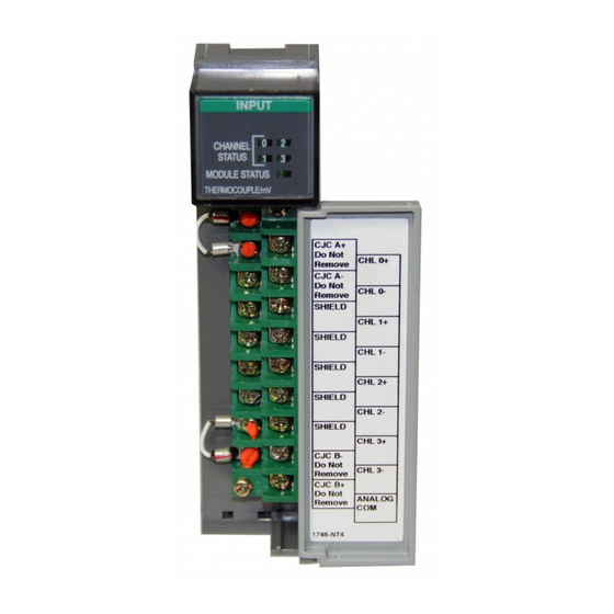
Page 6: Required Tools And Equipment
SLC™ 500 4-Channel Thermocouple/mV Input Module 1747-NT4 Thermocouple Module Hardware Features Channel Status INPUT LEDs (Green) Door Label CHANNEL STATUS MODULE STATUS Module Status THERMOCOUPLE/mV LED (Green) CJC A+ Do Not Remove CHL0+ CJC A± Removable Do Not Remove CHL0- Terminal Block SHIELD CHL1+... -
Page 7: Electrostatic Damage
SLC™ 500 4-Channel Thermocouple/mV Input Module Electrostatic Damage Electrostatic discharge can damage semiconductor devices inside this module if you touch backplane connector pins. Guard against electrostatic damage by observing the following precautions. Electrostatic discharge can degrade performance or cause ATTENTION permanent damage. -
Page 8: Fixed Expansion Chassis Considerations
SLC™ 500 4-Channel Thermocouple/mV Input Module Fixed Expansion Chassis Considerations The 2-slot, SLC 500 fixed I/O expansion chassis (1746-A2) will IMPORTANT support only specific combinations of modules. If you are using the thermocouple module in a 2-slot expansion chassis with another SLC I/O or communication module, refer to the SLC 500™Thermocouple/mV Input Module User Manual, 1746-6.6.1... - Page 9 SLC™ 500 4-Channel Thermocouple/mV Input Module To remove the terminal block: 1. Loosen the two terminal block release screws. 2. Grasp the terminal block at the top and bottom and pull outward and down. When removing or installing the terminal block, be careful not to damage the CJC sensors.
-
Page 10: Module Installation And Removal
SLC™ 500 4-Channel Thermocouple/mV Input Module Module Installation and Removal Module Installation Procedure 1. Align the circuit board of the thermocouple module with the card guides located at the top and bottom of the chassis. 2. Slide the module into the chassis until both top and bottom retaining clips are secured. -
Page 11: Terminal Wiring
SLC™ 500 4-Channel Thermocouple/mV Input Module Terminal Wiring The thermocouple module contains a green, 18-position, removable terminal block. The terminal pin-out is shown below. Disconnect power to the SLC before attempting to install, ATTENTION remove, or wire the removable terminal wiring block. (Terminal Block Spare Part Catalog Number 1746-RT32) Release Screw Max. -
Page 12: Thermocouple Junctions
SLC™ 500 4-Channel Thermocouple/mV Input Module Thermocouple Junctions There are three types of thermocouple junctions: • Grounded Junction - The measuring junction is physically connected to the protective metal sheath providing electrical continuity between junction and sheath. • Ungrounded Junction - The measuring junction is electrically isolated from the protective metal sheath. -
Page 13: Wiring Considerations
SLC™ 500 4-Channel Thermocouple/mV Input Module Wiring Considerations The possibility exists that grounded or exposed thermocouples ATTENTION can become shorted to a potential greater than that of the thermocouple itself. Due to possible shock hazard, care should be taken when wiring these types of thermocouples. See page 12 for definitions of thermocouple junctions. - Page 14 SLC™ 500 4-Channel Thermocouple/mV Input Module – If millivolt inputs are used, the terminal should be biased to a level within 2V of the signal of interest. Use 10KΩ resistors to create a resistive voltage divider as shown in the following circuit diagram. The Series A 1746-NT4 does not have an ANALOG COM terminal and cannot be used with multiple grounded and/or exposed thermocouples that touch electrically conductive...
-
Page 15: Wiring Input Devices To The Nt4
SLC™ 500 4-Channel Thermocouple/mV Input Module • Tighten terminal screws using a flat or cross-head screwdriver. Each screw should be turned tight enough to immobilize the wire’s end. Excessive tightening can strip the terminal screw. The torque applied to each screw should not exceed 6 - 8 in-lbs (0.7 - 0.9 Nm) for each terminal. -
Page 16: Cold-Junction Compensation (Cjc)
SLC™ 500 4-Channel Thermocouple/mV Input Module 4. At the other end of the cable, cut the drain wire and foil shield back to the cable and apply shrink wrap. 5. Connect the signal wires to the NT4 terminal block and the input. 6. -
Page 17: Module Addressing
SLC™ 500 4-Channel Thermocouple/mV Input Module Module Addressing The following memory map shows you how the output and input image tables are defined for the thermocouple module. Bit 15 Bit 0 Address Channel 0 Configuration Word Word 0 O:e.0 Channel 1 Configuration Word Word 1 O:e.1 Thermocouple... - Page 18 SLC™ 500 4-Channel Thermocouple/mV Input Module Channel Configuration Word - Bit Definitions Define To Select Make these bit settings in the Channel Configuration Word 11 10 9 15–12 Input type Thermocouple Type J Thermocouple Type K Thermocouple Type T Thermocouple Type E Thermocouple Type R Thermocouple Type S Thermocouple Type B...
-
Page 19: Specifications
SLC™ 500 4-Channel Thermocouple/mV Input Module Specifications Electrical Specifications Backplane Current Consumption 60 mA at 5V dc 40 mA at 24V dc Backplane Power Consumption 1.3W maximum (0.3W at 5V dc, 1.0W at 24V dc) Number of Channels 4 (backplane isolated) I/O Chassis Location Any I/O module slot except slot 0 A/D Conversion Method... - Page 20 SLC™ 500 4-Channel Thermocouple/mV Input Module Physical Specifications LED Indicators 5 green status indicators, one for each of 4 channels and one for module status Module ID Code 3510 Recommended Cable: for thermocouple inputs Appropriate shielded, twisted-pair thermocouple extension wire for mV inputs Belden #8761 or equivalent Maximum Wire Size...
- Page 21 SLC™ 500 4-Channel Thermocouple/mV Input Module Thermocouple Temperature and Millivolt Input Ranges Input Type Temperature Range Thermocouple Type J -210°C to +760°C (-346°F to +1400°F) Thermocouple Type K -270°C to +1370°C (-454°F to +2498°F) Thermocouple Type T -270°C to +400°C (-454°F to +752°F) Thermocouple Type E -270°C to +1000°C (-454°F to +1832°F) Thermocouple Type R...
- Page 22 SLC™ 500 4-Channel Thermocouple/mV Input Module Thermocouple/mV Input Module Accuracy Input Type With Autocalibration Without Autocalibration Maximum Error at Maximum Error at Temperature Drift +25°C +77°F (0°C to +60°C) ±1.06°C ±1.91°F ±0.0193°C/°C, °F/°F ±1.72°C ±3.10°F ±0.0328°C/°C, °F/°F ±1.43°C ±2.57°F ±0.0202°C/°C, °F/°F ±0.72°C ±1.3°F ±0.0190°C/°C, °F/°F...
- Page 23 SLC™ 500 4-Channel Thermocouple/mV Input Module Publication 1746-IN010D-EN-P - June 2004...
- Page 24 Rockwell Automation Support Rockwell Automation provides technical information on the Web to assist you in using its products. At http://support.rockwellautomation.com, you can find technical manuals, a knowledge base of FAQs, technical and application notes, sample code and links to software service packs, and a MySupport feature that you can customize to make the best use of these tools.
Need help?
Do you have a question about the Allen-Bradley B Series and is the answer not in the manual?
Questions and answers