Rockwell Automation Allen-Bradley C Series Installation Instructions Manual
Point i/o 5v dc and 24v dc very high speed counter module
Hide thumbs
Also See for Allen-Bradley C Series:
- Installation instructions manual (14 pages) ,
- User manual (90 pages) ,
- Installation instructions manual (16 pages)
Table of Contents
Advertisement
Quick Links
Installation Instructions
Original Instructions
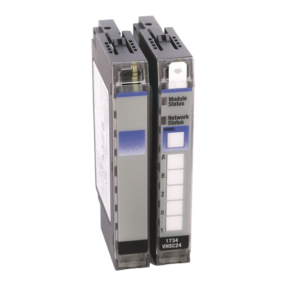
POINT I/O 5V DC and 24V DC Very High Speed Counter Module
Catalog Numbers 1734-VHSC5, 1734-VHSC24, 1734-VHSC24K, Series C
Catalog numbers with the suffix 'K' are conformal coated and their specifications are the same as non-conformal coated catalogs.
Topic
Summary of Changes
This publication contains the following new or updated information. This list includes substantive updates only and is not intended to reflect all changes.
Topic
Updated template
Updated UK and European Hazardous Location Approval
Updated Special Conditions for Safe Use
Updated IEC Hazardous Location Approval
Updated Input Specifications
Updated General Specifications
Updated Environmental Specifications
Updated Certifications
Page
1
5
6
6
7
8
9
9
13
14
Page
throughout
3
4
4
14
15
15
15, 16
Advertisement
Table of Contents

Related Manuals for Rockwell Automation Allen-Bradley C Series


Summary of Contents for Rockwell Automation Allen-Bradley C Series
-
Page 1: Table Of Contents
Installation Instructions Original Instructions POINT I/O 5V DC and 24V DC Very High Speed Counter Module Catalog Numbers 1734-VHSC5, 1734-VHSC24, 1734-VHSC24K, Series C Catalog numbers with the suffix ‘K’ are conformal coated and their specifications are the same as non-conformal coated catalogs. Topic Page Summary of Changes... - Page 2 Indien de apparatuur wordt gebruikt op een wijze die niet is gespecificeerd door de fabrikant, dan bestaat het gevaar dat de beveiliging van de apparatuur niet goed werkt. Rockwell Automation Publication 1734-IN003I-EN-E - September 2022...
- Page 3 Such locations correspond to Zone 2 classification according to UKEX regulation 2016 No. 1107 and ATEX directive 2014/34/EU. • May have catalog numbers followed by a “K” to indicate a conformal coating option. Rockwell Automation Publication 1734-IN003I-EN-E - September 2022...
- Page 4 The enclosure must be accessible only by the use of a tool. • This equipment shall be used within its specified ratings that are defined by Rockwell Automation. • Transient protection shall be provided that is set at a level not exceeding 140% of the peak rated voltage at the supply terminals to the equipment.
-
Page 5: Before You Begin
1734-TB, 1734-TBS mounting base Slide-in writable label Interlocking side pieces Insertable I/O module Mechanical keying (orange) Removable Terminal Block (RTB) handle DIN rail locking screw (orange) RTB with screw or spring clamp Module wiring diagram Rockwell Automation Publication 1734-IN003I-EN-E - September 2022... -
Page 6: Install The Mounting Base
Secure DIN rail to mounting surface approximately every 200 mm (7.8 in.) and use end-anchors appropriately. Be sure to ground the DIN rail properly. Refer to Industrial Automation Wiring and Grounding Guidelines, Rockwell Automation publication 1770-4.1, for more information. -
Page 7: Install The Removable Terminal Block
Insert the end opposite the handle into the base unit. This end has a curved section that engages with the wiring base. Rotate the terminal block into the wiring base until it locks itself in place. Rockwell Automation Publication 1734-IN003I-EN-E - September 2022... -
Page 8: Remove A Mounting Base
Repeat steps 1, 2, 3, and 4 for the module to the right. Use a small bladed screwdriver to rotate the orange base locking screw to a vertical position. This releases the locking mechanism. Lift straight up to remove. Rockwell Automation Publication 1734-IN003I-EN-E - September 2022... -
Page 9: Wire The Module
OS = Output on/off status bit – bit 8 for output 0, bit 9 for output 1 ZS = Z input status BS = B input status AS = A input status C = Stored data count ZD = Zero frequency detected Rockwell Automation Publication 1734-IN003I-EN-E - September 2022... - Page 10 Counter Configuration Counter 0 Counter Encoder X1 Encoder X2 Encoder X4 Period/Rate Continuous/Rate Rate measurement Pulse generator Store count disabled Mode 1 – Store/continue Mode 2 – Store/wait/resume Mode 3 – Store, reset/wait/start Rockwell Automation Publication 1734-IN003I-EN-E - September 2022...
- Page 11 The table shows the words you can exchange. You can read (Get) or write (Set) data using an Explicit Message. Assemblies Instances Services Field Bytes (Dec/Hex) #101 (0x65) Present channel data Status #102 (0x66) Stored channel data Rockwell Automation Publication 1734-IN003I-EN-E - September 2022...
- Page 12 Output 1 ties Alignment (Reserved = 0) Rollover value Preset value ON value #1 OFF value #1 ON value #2 OFF value #2 ON value #3 OFF value #3 ON value #4 OFF value #4 Rockwell Automation Publication 1734-IN003I-EN-E - September 2022...
-
Page 13: Interpret Status Indicators
Flashing yellow Output is toggling. Output status Yellow Output is active and under control. Flashing red Output is faulted (Open, short, or no output power). Flashing red/yellow Output is toggling and faulted (possibly open). Rockwell Automation Publication 1734-IN003I-EN-E - September 2022... -
Page 14: Specifications
Dimensions (H x W x D), approx. 56.0 x 12.0 x 75.5 mm (2.21 x 0.47 x 2.97 in.) Weight 0.03 kg (0.07 lb) (1) (2) 1 – on signal ports Wiring category Rockwell Automation Publication 1734-IN003I-EN-E - September 2022... - Page 15 II 3 G Ex ec IIC T4 Gc DEMKO 04 ATEX 0330347X UL22UKEX2478X Korean Registration of Broadcasting and Communications Equipment, compliant with: Article 58-2 of Radio Waves Act, Clause 3 Russian Customs Union TR CU 020/2011 EMC Technical Regulation Rockwell Automation Publication 1734-IN003I-EN-E - September 2022...
- Page 16 Figure 3 - Input Derating Curve for 1734-VHSC24 and 1734-VHSC24K 28.8 Input Voltage (V) Module Ambient Still Air Temperature ( °C) IMPORTANT Exceeding the maximum input voltage can cause permanent damage to the input. Rockwell Automation Publication 1734-IN003I-EN-E - September 2022...
- Page 17 POINT I/O 5V DC and 24V DC Very High Speed Counter Module Installation Instructions Notes: Rockwell Automation Publication 1734-IN003I-EN-E - September 2022...
- Page 18 Rockwell Otomasyon Ticaret A.Ş. Kar Plaza İş Merkezi E Blok Kat:6 34752 İçerenköy, İstanbul, Tel: +90 (216) 5698400 EEE Yönetmeliğine Uygundur Allen-Bradley, expanding human possibility, FactoryTalk, POINT I/O, POINTBus, Rockwell Automation, Studio 5000 Logix Designer, and TechConnect are trademarks of Rockwell Automation, Inc.
Need help?
Do you have a question about the Allen-Bradley C Series and is the answer not in the manual?
Questions and answers