Rockwell Automation Allen-Bradley C Series Installation Instructions Manual
Point i/o 2 current and 2 voltage input analog modules
Hide thumbs
Also See for Allen-Bradley C Series:
- Installation instructions manual (18 pages) ,
- User manual (90 pages) ,
- Installation instructions manual (16 pages)
Table of Contents
Advertisement
Quick Links
Installation Instructions
Original Instructions
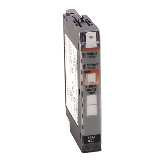
POINT I/O 2 Current and 2 Voltage Input Analog Modules
Catalog Numbers 1734-IE2C, 1734-IE2CK, 1734-IE2V, 1734-IE2VK, series C
Catalog numbers with the suffix 'K' are conformal coated and their specifications are the same as non-conformal coated catalogs.
f
Topic
Summary of Changes
This publication contains the following new or updated information. This list includes substantive updates only and is not intended to reflect all changes.
Topic
Updated template
Page
1
4
6
6
7
8
8
10
10
11
13
Page
throughout
4
4
4
6
11
12
13
Advertisement
Table of Contents

Related Manuals for Rockwell Automation Allen-Bradley C Series


Summary of Contents for Rockwell Automation Allen-Bradley C Series
-
Page 1: Table Of Contents
Installation Instructions Original Instructions POINT I/O 2 Current and 2 Voltage Input Analog Modules Catalog Numbers 1734-IE2C, 1734-IE2CK, 1734-IE2V, 1734-IE2VK, series C Catalog numbers with the suffix ‘K’ are conformal coated and their specifications are the same as non-conformal coated catalogs. Topic Page Summary of Changes... - Page 2 • Secure any external connections that mate to this equipment by using screws, sliding latches, threaded connectors, or other means provided with this product. • Do not disconnect equipment unless power has been removed or the area is known to be nonhazardous. Rockwell Automation Publication 1734-IN027E-EN-E - June 2023...
- Page 3 • Substitution of components may impair suitability for Class I • La substitution de composants peut rendre cet équipement inadapté à Division 2. une utilisation en environnement de Classe I Division 2. Rockwell Automation Publication 1734-IN027E-EN-E - June 2023...
-
Page 4: Before You Begin
The enclosure must be accessible only by the use of a tool. • This equipment shall be used within its specified ratings that are defined by Rockwell Automation. • Transient protection shall be provided that is set at a level not exceeding 140% of the peak rated voltage at the supply terminals to the equipment. - Page 5 Interlocking side pieces Slide-in writable label Mechanical keying (orange) Insertable I/O module DIN rail locking screw (orange) Removable terminal block (RTB) handle Module wiring diagram One-piece terminal base with screw (1734-TOP) or spring clamp (1734-TOPS) Rockwell Automation Publication 1734-IN027E-EN-E - June 2023...
-
Page 6: Install The Mounting Base
Secure DIN rail to mounting surface approximately every 200 mm (7.8 in.) and use end-anchors appropriately. Be sure to ground the DIN rail properly. See Industrial Automation Wiring and Grounding Guidelines, Rockwell Automation publication 1770-4.1, for more information. -
Page 7: Install The Removable Terminal Block
WARNING: For 1734-RTBS and 1734-RTB3S, to latch and unlatch the wire, insert a bladed screwdriver (catalog number 1492-N90 – 3 mm diameter blade) into the opening at approximately 73° (blade surface is parallel with top surface of the opening) and push up gently. 85° 73° Rockwell Automation Publication 1734-IN027E-EN-E - June 2023... -
Page 8: Remove A Mounting Base
1734-IE2C, 1734-IE2CK 1734-IE2V, 1734-IE2VK 1734 IE2V Input 1 Input 0 Input 0 Input 1 CHAS GND CHAS GND CHAS GND CHAS GND CHAS GND = Chassis ground C = Common V = Supply Rockwell Automation Publication 1734-IN027E-EN-E - June 2023... - Page 9 Secure DIN rail to mounting surface approximately every 200 mm (7.8 in.) and use end-anchors appropriately. Be sure to ground the DIN rail properly. See Industrial Automation Wiring and Grounding Guidelines, Rockwell Automation publication 1770-4.1, for more information.
-
Page 10: Communicate With Your Module
Communication faulted device – The device has detected a network access error and is in communication faulted state. Device has received Flashing red/green and accepted an Identity Communication Faulted Request – Long protocol message. Rockwell Automation Publication 1734-IN027E-EN-E - June 2023... -
Page 11: Specifications
1 green/red – network status 2 green/red – input status Keyswitch position POINTBus™ current, max 75 mA @ 5V DC Power dissipation, max 0.6 W @ 28.8V DC 0.75 W @ 28.8V DC Rockwell Automation Publication 1734-IN027E-EN-E - June 2023... -
Page 12: Updated Environmental Specifications
±3 kV at 5 kHz on signal ports IEC 61000-4-5: Surge transient immunity ±2 kV line-earth (CM) on shielded ports IEC61000-4-6: Conducted RF immunity 10V rms with 1 kHz sine-wave 80% AM from 150 kHz…80 MHz Rockwell Automation Publication 1734-IN027E-EN-E - June 2023... -
Page 13: Additional Resources
POINT I/O digital and analog modules and POINTBlock I/O modules. Industrial Automation Wiring and Grounding Guidelines, publication 1770-4.1 Provides general guidelines for installing a Rockwell Automation industrial system. Product Certifications website, rok.auto/certifications Provides declarations of conformity, certificates, and other certification details. - Page 14 Rockwell Otomasyon Ticaret A.Ş. Kar Plaza İş Merkezi E Blok Kat:6 34752 İçerenköy, İstanbul, Tel: +90 (216) 5698400 EEE Yönetmeliğine Uygundur Allen-Bradley, expanding human possibility, FactoryTalk, POINT I/O, POINTBus, Rockwell Automation, Studio 5000 Logix Designer, and TechConnect are trademarks of Rockwell Automation, Inc.
Need help?
Do you have a question about the Allen-Bradley C Series and is the answer not in the manual?
Questions and answers