
Related Manuals for Teltonika FMA110


Summary of Contents for Teltonika FMA110
- Page 1 FMA110 User Manual V1.15 *This version is suitable for device with universal firmware version 01.27.xx and later versions...
-
Page 2: Table Of Contents
......................11 2.4 E LECTRICAL CHARACTERISTICS 2.5 A .......................12 BSOLUTE AXIMUM ATINGS 3 CONNECTION, PINOUT, ACCESSORIES.................... 13 3.1 H FMA110 :................13 OW TO INSERT CARD INTO DEVICE ......................14 3.2 I FMA110 NSTALLING DRIVERS 3.2.1 System requirements for FMxxxx configurator..............14 3.2.2 Drivers..........................14... - Page 3 5.15.2 Event Generating......................52 5.15.3 Hysteresis........................52 6 SMS COMMAND LIST........................53 6.1 SMS ........................53 COMMAND LIST 6.1.1 getstatus........................... 54 6.1.2 getweektime........................55 6.1.3 getops..........................55 6.1.4 getcfgtime.........................55 6.1.5 getgps..........................55 6.1.6 getver..........................55 6.1.7 getinfo..........................56 6.1.8 getio..........................56 6.1.9 readio #..........................57 6.1.10 setdigout ## Y1 Y2......................57 6.1.11 setdigoutX Z Y.........................
- Page 4 8.4.2 APN Name (ID=1242)......................66 8.4.3 APN username (ID=1243)....................66 8.4.4 APN Password (ID=1244)....................66 8.4.5 Domain (ID=1245)......................66 8.4.6 Target Server Port (ID=1246)....................66 8.4.7 Protocol (ID=1247)......................67 8.4.8 Always online (ID=1248)....................67 8.4.9 SMS Login (ID=1252)......................67 8.4.10 SMS Password (ID=1253)....................67 8.4.11 SMS data sending settings (ID=1250)................67 8.4.12 SMS Data send week time schedule (ID=1273)..............
- Page 5 8.7.7 I/O#1 element SMS event configuration (ID=100)............87 8.8 LV-CAN ........................91 PARAMETERS 8.8.1 LVCAN mode (ID=1600)....................91 8.8.2 Send data with 0, if ignition is off (ID=1601)..............92 9 FMA110 WITH LV-CAN200 AND ALL-CAN300 CAN ADAPTERS............92 9.1 P LV-CAN200 ALL-CAN300............92 URPOSE OF DAPTERS ............
- Page 6 ................95 9.3 SIMPLE-CAN - CAN-BUS CONTACTLESS READER 9.4 C FMA110 C ALL-CAN300 LV-CAN200..........96 ONNECTING AN ADAPTERS ......................... 97 9.5 FM11 C ONFIGURATION 9.6 P ID......................... 101 ARAMETERS 9.7 SMS C ......................... 107 ONFIGURATION 9.8 CAN P SMS................... 109...
-
Page 7: Introduction
10 V...30 V DC. To avoid mechanical damage, it is advised to transport the FMA110 device in an impact- proof package. Before usage, the device should be placed so that its LED indicators are visible, which show the status of operation the device is in. -
Page 8: Legal Notice
AC/DC – Alternating Current/Direct Current I/O – Input/Output Record – AVL data stored in FMA110 memory. AVL data contains GPS and I/O information AVL packet - data packet that is being sent to server during data transmission. AVL packet contains from 1 to 50 records. -
Page 9: Basic Characteristics
Basic characteristics GSM / GPRS features: Quad band supported (GSM 850 / 900 / 1800 / 1900 MHz); GPRS Multi-Slot Class 12(up to 240 kbps); GPRS Mobile Station Class B; SMS (text, data). GNSS features: Tracking: 33/ 99 acquisition channels; ... -
Page 10: Technical Features
Overvoltage protection (new devices with order code FMA110 Vxxxxx): Description Voltage Duration Normal operation 10-30V Unlimited Protection turns on, device turns off. Unlimited Maximum voltage <70V Unlimited Maximum voltage impulse 5 mili seconds Technical features Part name Physical specification Technical details Power supply 10...30 V DC... -
Page 11: Electrical Characteristics
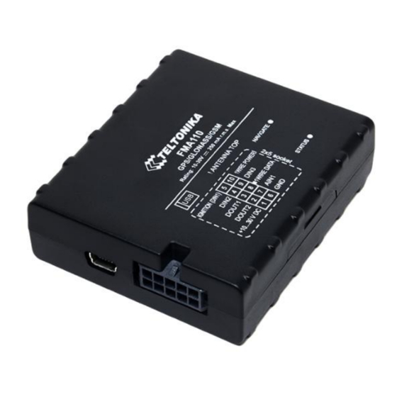
Figure 1 FMA110 view & dimensions (tolerance ±2mm) Electrical characteristics VALUE Min. Typ. Max. Unit CHARACTERISTIC DESCRIPTION Supply Voltage: Supply Voltage (Recommended Operating Conditions) Digital Output (Open Drain grade): Drain current (Digital Output OFF) Drain current (Digital Output ON, Recommended Operating Conditions) -
Page 12: Absolute Maximum Ratings
Short circuit current (U = 0) Note: Analog Input error margin can increase if temperature varies. If Analog input is not connected FMA110 will still measure certain numbers and it cannot be 0. This measurement is influenced by hardware components. Absolute Maximum Ratings VALUE Min. -
Page 13: Connection, Pinout, Accessories
3 CONNECTION, PINOUT, ACCESSORIES How to insert SIM card into FMA110 device: Gently open FMA110 case using screwdrivers Remove FMA110 case Insert SIM card as shown... -
Page 14: Installing Fma110 Drivers
Device is ready Attach top housing cover Installing FMA110 drivers 3.2.1 System requirements for FMxxxx configurator Software requirements Operating system 32-bit and 64-bit: Windows XP with SP3 or later, Windows Vista, Windows 7, Windows 8/8.1, Windows 10 Microsoft .NET framework v4.0 (https://www.microsoft.com/) -
Page 15: Installing Drivers
3.2.3 Installing drivers Extract and run VCPDriver_V1.3.1_Setup.exe. This driver is used to detect FMA110 device connected to the computer. Click 'Next' in driver installation window (figures below): Figure 2 Driver installation window This will launch device driver installation wizard. In the following window click ‘Next’... -
Page 16: Navigate Led
Navigate LED Behaviour Meaning Permanently switched on GPS signal is not received Blinking every second Normal mode, GPS is working GPS is turned off because: Deep sleep mode GPS module is turned off Status LED Behaviour Meaning Blinking every second Normal mode Blinking every 2 seconds Deep sleep mode... -
Page 17: Usb
Mini USB connector Figure 6 Mini USB type B connector FMA110 connected to PC creates an STM Virtual COM Port, which can be used as a system port (to flash firmware and configure the device): Figure 7 COM-Ports Accessories Note: Teltonika does not provide any additional equipment like panic buttons, door sensors or others. - Page 18 Left row of pins Right row of pins 1W. PWR (FMA110 – pin10) Vpp (+5 Volts DC) – 1W. Data power source for (FMA110 – pin8) external digital sensor Output from external (FMA110 – pin6) digital sensor Digital Input Figure 8 Digital thermometer DS1820 and TTJ100 connection scheme...
- Page 19 A fuel tank level sensor exists in most cars, which shows the approximate fuel level in the driver’s indicator panel. It is possible to connect FMA110 Analog input to it (if sensor returns analogue signal proportional to fuel level). Figure 10 shows the connection scheme to the FMA110 and fuel tank sensor.
- Page 20 Immobilizer relay When connected as shown below, FMA110 disables engine starter when output is ON. More details about relays can be found below. Figure 13 Immobilizer relay connection Relays An ordinary automotive relay is used to invert input signal or to immobilize engine starter.
-
Page 21: Firmware
FMA110 functionality is always improving, new firmware versions are developed. Current module firmware version can be retrieved from Configurator. Connect FMA110 to PC with the USB cable. Launch “Firmware Updater”, select COM port to which device is connected, click connect, and when IMEI and Firmware version fields are filled, start the update. -
Page 22: Operational Basics
GPS data and I/O information. Module uses GPS receiver to acquire GPS data and is powered with four data acquire methods: time-based, distance-based, angle-based and speed- based method. Note, that if FMA110 loses connection to GPS satellites, it continues to make records, however coordinate in these records remains the same (last known coordinate). -
Page 23: Sleep Modes
(defined period) starts counting when device is in STOP mode. After timeout is reached and all conditions for sleep mode are met, device goes to sleep mode. While in sleep mode, FMA110 turns GPS module off and it is not making new periodic records. Only event records is being recorded with last known coordinate and sent to AVL server. -
Page 24: Virtual Odometer
It keeps adding these intervals until it is time to make a record, then FMA110 records its location and adds odometer value, which is equal to the sum of all distances, measured every second. -
Page 25: Trip
Jamming scenario. Radio jamming is the (usually deliberate) transmission of radio signals that disrupt communications by decreasing the signal to noise ratio. When jamming detection is enabled, FMA110 informs (with buzzer or LED, connected to DOUT) driver about jamming event. Jamming can be deactivated with iButton. -
Page 26: Geofencing
FMA110 has one user editable profile, which can be loaded from device, and saved. User can also revert to default settings, by pressing Load Defaults button. After any modification of configuration settings it has to be saved to FMA110 device, otherwise it will not be written to device. - Page 27 Figure 17 Recommended Configuration window Recommended Configuration mode uses predefined data acquisition values. In this configuration mode it is only required to enter network parameters. In Advanced Configuration mode FMA110 is more configurable.
- Page 28 ‘Add Keyword’ / ‘Change Keyword’ / ‘Switch Security Off’– buttons are used to protect configurator from unauthorized access to configuration. Keyword is 4 – 10 symbol length. If keyword is set, every time user reconnects FMA110 to USB port, user will be asked to provide valid keyword when connecting FMA110 to configurator.
-
Page 29: Record Storage
Record storage FMA110 can store up to 3500 data records if GSM or GPRS is not available at the moment. It will send data later when GPRS is available again. Note that FMA110 can have memory full of records. - Page 30 For manual ignition user has to choose power voltage levels by himself. For automatic ignition FMA110 device detects system voltage and automatically detects ignition. In 12 V systems ignition is on when voltage is between 13,2 – 16 V...
-
Page 31: Records Settings
Essential fields in ‘SMS’ part are ‘Login’ and ‘Password’. The login and password are used with every SMS sent to FMA110. If login and password are not set, in every SMS sent to FMA110 device two spaces before command have to be used (<space><space><command>). - Page 32 SMS request messages – answers are always sent back to sender telephone number. FMA110 can send binary SMS with 24-coordinates-in-one-SMS. It is used in areas where no GPRS coverage is available. Module collects data and sends to server binary SMS containing information about last 24 collected points.
-
Page 33: Gsm Settings, Operator List
Figure 23 Operator list configuration If operator list is left empty, it will allow using GPRS to any GSM operator. Please note that FMA110 will work in Unknown mode only (make sure it is configured to allow data sending – GPRS context is enabled). -
Page 34: Data Acquisition Mode Settings
Figure 25 Black operator list configuration 5.13 Data Acquisition Mode settings Data Acquisition Modes are an essential part of FMA110 device, it is also highly configurable. By configuration user defines how records will be saved and sent. There are three different modes: Home, Roaming and Unknown. - Page 35 This functionality allows having different AVL records acquire and send parameters values when object is moving or stands still. Vehicle moving or stop state is defined by Stop Detection Source parameter. There are 3 ways for FMA110 to switch between Vehicle on Stop and Vehicle Moving modes see section 5.7.
- Page 36 Figure 27 Data Acquisition Mode configuration...
- Page 37 New GPRS context is opened if time is 10 minutes till time checked in table. Therefore if all boxes are checked, FMA110 is able to open new connection anytime. At scheduled time match FMA110 checks for GPRS session activity.
- Page 38 Note: Keep in mind that FMA110 operates in GMT:0 time zone, without daylight saving. FMA110 is able to collect records using three methods at the same time: time, distance and angle based data acquisition: Time based data acquiring (Min. period) – records are being acquired every time when defined interval of time passes.
-
Page 39: Features Settings
5.14 Features settings For more information about available Scenarios, Trip, Geofencing and iButton list, refer to 5.4 chapter. 5.14.1 Scenarios settings In Scenarios window four different scenarios are available to use. More than one scenario can manage the same DOUT. If DOUT Control is disabled, scenarios can only generate events without digital output activation. -
Page 40: Trip Settings
event is detected and DOUT is activated it can be deactivated with iButton. If iButton list is not empty, then digital output can be deactivated only with authorized iButton. Immobilizer If Dout Control is disabled, scenario will only generate events without digital output activation. - Page 41 Start odometer value with can be set using configurator („set“ button) or SMS/GPRS (setparam/getparam) commands. This parameter can not be configured via TCP config. If this value is not set, FMA110 starts counting from 0. Continuous odometer works irrespective of the Trip functionality.
-
Page 42: Geofencing Settings
FMA110 remembers new iButton ID. FMA110 forgets iButton ID after ignition is off and trip ignition off timeout is reached. Figure 37 Remember iButton parameter in configurator 5.14.3 Geofencing settings FMA110 has 5 configurable Geofence zones and it can generate an event when defined Geofence zone border is crossed. - Page 43 X2 or R – geofence zone upper right corner X coordinate (longitude) or radius of circle when Circular zone is used (radius in meters); Y2 – geofence zone upper right corner Y coordinate (latitude); Figure 37 Geofence configuration AutoGeofencing settings AutoGeofence –...
-
Page 44: Sms Events
AutoGeofence I/O event When any of the above events is triggered, FMA110 sends a configured SMS message to a defined phone number. If SMS events is activated, but there are no numbers defined in SMS events PreDefined Numbers list (figure 34), then the device will not send any messages. - Page 45 The sent SMS messages format is according to: “Date Time EventText” For example, if FMA110 is configured to send an SMS, when Digital Input 1 reaches High level, with priority High and configured to generate event on both range enter and exit (figure 35), then the sent SMS is: “2012/6/7 12:00:00 Digital Input 1”...
-
Page 46: Sms Events Configuration
ATTENTION! If FMA110 is in Deep Sleep mode and SMS event occurs with LOW priority (which does not wake up FMA110), then the device does not send the message. It is saved in device memory until it wakes up from Deep Sleep mode and GSM modem starts working normally. - Page 47 Trip In order to configure Trip SMS events click on Trip window and Enable Trip feature (figure 37). Then go to GSM -> SMS -> SMS Events settings and Enable Trip SMS event. After enabling SMS Events (figure 38), trip event will be triggered and message sent, when Trip starts (GNSS speed exceeds the speed in Start Speed (ex.
- Page 48 Figure 44 Geofence SMS event configuration AutoGeofence SMS events for AutoGeofence are configured the same as in Geofence. AutoGeofence is next to Geofence configuration (figure 40), for SMS events configuration, go to GSM -> SMS -> SMS Events. Figure 45 AutoGeofence SMS event configuration...
-
Page 49: I/Osettings
I/O events FMA110 sends SMS event message when a configured I/O property enters and/or exits its configured High/Low boundaries or Hysteresis event generation is chosen (Monitoring does not generate event, so SMS event could not be configured). Every IO element SMS event can be configured to send individual message to different numbers. - Page 50 Digital output 2 state Logic: 0 / 1 PDOP Probability * 10; 0-500 HDOP Probability * 10; 0-500 Trip distance Distance between two records: m 0 – not deep sleep mode, 1 – GPS sleep Sleep mode mode, 2 – deep sleep mode Cell ID GSM base station ID Location Area code (LAC), it depends on...
- Page 51 Figure 47 I/O settings Enabled or disabled field – allows enabling I/O element so it is added to the data packet and is sent to the server. By default all I/O element are disabled and FMA110 records only GPS coordinates.
-
Page 52: Monitoring
5.15.1 Monitoring I/O monitoring starts after enabling I/O element and setting up I/O parameters as it is shown below: Figure 48 I/O settings 5.15.2 Event Generating Events happen when the value of enabled I/O intersects thresholds (enter, exit or on both) predefined by High and Low level thresholds. -
Page 53: Sms Command List
Figure 51 Event generation according hysteresis algorithm 6 SMS COMMAND LIST Read chapter 5.11 to know how to construct a proper SMS message and send it to FMA110 device. All commands are case sensitive. While FMA110 operates in Deep Sleep mode and user tries to send SMS message it cannot arrive to FMA110 device, because GSM/GPRS module is disabled most of the time (wake up depends on Send Period parameter). -
Page 54: Getstatus
# - ID value. setparam # # Set parameter value according entered ID and Value. 1.# - ID value. 2.# - New Parameter Value getparam 1271 X X values can be 1,2,3. flush #,#,#,#,#,#,# Initiates all data sending to specified target server 1.# - IMEI 2.# - APN 3.# - LOGIN... -
Page 55: Getweektime
Example: Data Link: 0 GPRS: 1 Phone: 0 SIM: 0 OP: 24602 Signal: 5 NewSMS: 0 Roaming: 0 SMSFull: 0 LAC: 1 Cell ID: 864 6.1.2 getweektime Response details Description Clock Sync Indicates system clock synchronization status. 0 – System is not synchronized, 1 –... -
Page 56: Getinfo
to load Bootloader Ver Bootloader Version Modem App Ver Version of modem application (veiks: nuo 00.05.14) Revision Firmware revision Example: Code Ver:01.06.15 Rev:1 Device IMEI:353976010139156 Device ID:000001 Bootloader Ver: 01.09 Modem APP Ver:TM11Q_R_01.00.03.03_002 6.1.7 getinfo Response details Description Device Initialization Time RTC Time Restart Counter Error Counter... -
Page 57: Readio
6.1.9 readio # Response details Description I/O element ID Value I/O Element value Example: I/O ID:3 Value:0 6.1.10 setdigout ## Y1 Y2 Sets digital outputs to ON or OFF state (for some time if needed). Value is written as a row for OUT1 and OUT2 values. -
Page 58: Readops
6.1.16 readops # Send from device Operator List. 1 – send first 20 operator codes, 2 – send from 21 to 40 operator codes, 3 – send all other operator codes. 6.1.17 flush #,#,#,#,#,#,# Initiates all data sending by GPRS to specified target server. Comma separated parameters go as numbered: 1.# - IMEI 2.# - APN... -
Page 59: Lvcangetprog
6.1.21 lvcangetprog CAN program number can be obtained via SMS: SMS Text: “lvcangetprog” Response: “CAN Program Nr: XXXX” 6.1.22 lvcansetprog # Set LV-CAN program number via SMS: SMS Text: “lvcansetprog 139” Response: “CAN program Nr:139” 6.1.23 lvcangetinfo Get LV-CAN info by SMS Full LV-CAN information via SMS: SMS Text: “... -
Page 60: Setkey
Fault codes are written in international format, so it is easy to decript it. A few links which help to decript DTC error codes: http://www.totalcardiagnostics.com/support/Knowledgebase/Article/View/21/0/generic manufacturer-obd2-codes-and-their-meanings http://www.engine-codes.com/ http://www.obd-codes.com/trouble_codes/ 6.1.25 setkey Changes device current configuration keyword. Example: opa opa setkey 0101 3333 Here 0101 is an old keyword, 3333 is a new keyword. -
Page 61: Debug Mode
7 Debug mode FMA110 is able to transmit its current state when connected to PC using USB cable. It is used to detect errors and provide information to possible solutions when operating as unexpected. Download Terminal from: http://avl1.teltonika.lt/Downloads/Software/Terminal.zip. After launching terminal choose baud rate 115200 and hardware control – none. Select COM port which is assigned to “Virtual COM Port”. -
Page 62: Parameter List
(value 1) module reduces level of power usage by turning GPS module to sleep, in deep sleep mode (value 2) module turns GPS module to sleep and switch GSM module off (note, that FMA110 do not receive SMS while in deep sleep). Minimum... -
Page 63: Static Navigation (Id=1003)
8.2.5 Static Navigation (ID=1003) When static navigation is enabled, FMA110 filters out GPS jumps, when it is not moving. When it is disabled, it does not make any changes to collected GPS data. Minimum Maximum Recommended Goes with (depends on) -
Page 64: Power Voltage High Level (Id=1005)
8.2.9 Power Voltage High Level (ID=1005) When ignition source is selected as Power Voltage High level for ignition detection must be set. Minimum Maximum Recommended Goes with (depends on) Value value value value parameters type Ignition source (ID=1004) 30000 Power Voltage Low Level (ID=1006) 8.2.10 Power Voltage Low Level (ID=1006) When ignition source is selected as Power Voltage High level for ignition detection must be... -
Page 65: Records Parameters
Records parameters 8.3.1 8.3.1 Sorting (ID=1010) Record sorting parameter is responsible for record sorting order. Value of 0 arranging data starting from newest, while value of 1 arranging data starting from oldest. Minimum Maximum Recommended Goes with (depends on) Value value value value... -
Page 66: Apn Name (Id=1242)
8.4.2 APN Name (ID=1242) Parameter defines GPRS Access Point Name. Minimum Maximum Recommended Goes with (depends on) Value value value value parameters type GPRS content ac ivation 32 char (ID=1240) Empty S8[32] string APN username (ID=1243) APN Password (ID=1244) 8.4.3 APN username (ID=1243) Parameter defines APN username. -
Page 67: Protocol (Id=1247)
8.4.7 Protocol (ID=1247) Parameter defines GPRS data transport protocol. Module can use TCP or UDP transport protocol to send data to server. For TCP protocol value is 0, for UDP protocol value is 1. Minimum Maximum Recommended Goes with (depends on) Value value value... -
Page 68: Authorized Phone Numbers (Id=1260-1269)
8.4.13 Authorized phone numbers (ID=1260-1269) If at least one number is entered then only those number can send messages to device. Number must be entered without “+” or “00”. Example: 37060012346 Minimum Maximum Recommended Goes with (depends on) Value value value value parameters... -
Page 69: Data Acquisition Modes Parameters
Data Acquisition Modes parameters 8.5.1 Home Network GSM operator code “Vehicle on STOP” parameters 8.5.2 Min Period (ID=1540) This parameter indicates time interval in seconds in order to acquire new record. If value is 0 it means no records by min period will be saved. Minimum Maximum Recommended... -
Page 70: Home Network Gsm Operator Code "Vehicle Moving" Parameters
It should be sent as UTF8 encoded string. 8.5.6 Home Network GSM operator code “Vehicle MOVING” parameters 8.5.6.1 Min Period (ID=1550) This parameter indicates time interval in seconds in order to acquire new record. If value is 0 it means no records by min period will be saved. Minimum Maximum Recommended... -
Page 71: Send Period (Id=1554)
Minimum Maximum Recommended Goes with (depends on) Value value value value parameters type Min Period (ID=1550) Min Distance (ID=1551) Min Angle (ID=1552) Min Speed (ID=1556) GPRS Week Time (ID=1555) 8.5.6.5 Send Period (ID=1554) This parameter indicates frequency (time interval in seconds) of sending data to server. Minimum Maximum Recommended... -
Page 72: Min Saved Records (Id=1563)
8.5.7.2 Min Saved Records (ID=1563) This parameter defines minimum number of records in one data packet that can be sent to server. It has higher priority than Data Send Period (ID=1564). Minimum Maximum Recommended Goes with (depends on) Value value value value parameters... -
Page 73: Min Saved Records (Id=1573)
new record is stored. This parameter is operational, when speed is higher than 10km/h. If value is 0 it means no records by min angle will be saved. Minimum Maximum Recommended Goes with (depends on) Value value value value parameters type Min Period (ID=1570) Min Distance (ID=1571) -
Page 74: Unknown Network Gsm Operator Code "Vehicle On Stop" Parameters
Minimum Maximum Recommended Goes with (depends on) Value value value value parameters type Min Speed (ID=1576) 8.5.9 Unknown Network GSM operator code “Vehicle on STOP” parameters 8.5.9.1 Min Period (ID=1580) This parameter indicates time interval in seconds in order to acquire new record. If value is 0 it means no records by min period will be saved. -
Page 75: Min Distance (Id=1591)
8.5.10.2 Min Distance (ID=1591) This parameter indicates distance in meters in order to acquire new record. Record is stored when the distance between previous records is greater than parameter’s value. If value is 0 it means no records by min distance will be saved. Minimum Maximum Recommended... -
Page 76: Gprs Week Time (Id=1595)
8.5.10.6 GPRS Week Time (ID=1595) Read chapter 8.5.5. 8.5.10.7 Min Speed (ID=1596) This parameter indicates speed difference in order to acquire new record. If speed difference between last recorded coordinate and current position is greater than defined value, new record is stored. If value is 0 it means no records by min distance will be saved. Minimum value of Min Speed parameter is 10 km/h. -
Page 77: Max Acceleration Force (Id=1892)
8.6.4 Max Acceleration Force (ID=1892) It is max allowed acceleration force which can be reached while accelerating without triggering harsh acceleration event. Minimum Maximum Recommended Goes with (depends on) Value value value value parameters type 0.25 0.85 0.25 Float Green driving scenario (ID=1890) 8.6.5 Max Braking Force (ID=1893) It is max allowed braking force which can be reached while braking without triggering... -
Page 78: Jamming Scenario (Id=1898)
8.6.10 Jamming scenario (ID=1898) This parameter enables/disables Jamming scenario. 0 – disable, 1 – enable. Minimum Maximum Recommended Goes with (depends on) Value value value value parameters type 8.6.11 Jamming digital output control (ID=1899) This parameter defines digital output control on Jamming scenario. 0 – disable, 1 – DOUT1, 2 –... -
Page 79: Immobilizer Digital Output Control (Id=1904)
8.6.16 Immobilizer digital output control (ID=1904) This parameter defines digital output control on Immobilizer scenario. 0 – disable, 1 – DOUT1, 2 – DOUT2. Minimum Maximum Recommended Goes with (depends on) Value value value value parameters type Immobilizer scenario (ID=1903) 8.6.17 iButton list checking (ID=1905) This parameter enables/disables iButton list chenking. -
Page 80: Start Speed (Id=1281)
8.6.22 Start Speed (ID=1281) This parameter represents speed, which is detected as minimum speed to indicate TRIP START and generate event. Minimum Maximum Recommended Goes with (depends on) Value value value value parameters type Tip (ID=1280) 8.6.23 Ignition Off Timeout (ID=1282) This parameter represents timeout to wait if ignition is off in order to detect TRIP STOP and generate event. -
Page 81: Geofence Zone #1 Shape (Id=1030)
Minimum Maximum Recommended Goes with (depends on) Value value value value parameters type 1000000 1000 All Geofencing parameters 8.6.27.2 Geofence Zone #1 Shape (ID=1030) Geofence shape parameter can be: circle – value 0; rectangle – value 1. Minimum Maximum Recommended Goes with (depends on) Value value... -
Page 82: Geofence Zone #1 Longitude (X2) (Id=1035)
8.6.27.7 Geofence Zone #1 Longitude (X2) (ID=1035) Parameter has two meanings depending on zone shape. If shape is a rectangle, then ID=1035 is right upper corner X coordinate. If shape is a circle, then ID=1035 is radius of circle with center of ID=1033 and ID=1034. For rectangle: Minimum Maximum... -
Page 83: Deactivate By (Id=1100)
8.6.28.3 Deactivate by (ID=1100) Parameter defines Autogeofence deactivation source. Value 1 is dedicated for attached iButton, value 0 – for Ignition. Minimum Maximum Recommended Goes with (depends on) Value value value value parameters type Enable/Disable (ID=1101) iButton List (ID=3500-3999 ) 8.6.28.4 AutoGeofence event Priority (ID=1103) Parameter defines AutoGeofence event priority: 0 is low, 1 –... -
Page 84: I/Oparameters
I/O parameters I/O properties are additional data sources which are recorded along with usual GPS data. 8.7.1 I/O#1 property parameter (ID=1300) Parameter defines I/O property value. Possible values: enabled (1), disabled (0). Minimum Maximum Recommended Goes with (depends on) Value value value value... -
Page 85: I/O#1 Logic Operand (Id=1304)
Minimum Maximum Recommended Goes with (depends on) Value value value value parameters type I/O#1 property parameter (ID=1300) I/O#1 priority (ID=1301) -2147483647 2147483647 I/O#1 High level (ID=1302) I/O# logic operand (ID=1304) I/O#1 Averaging length (ID=1305) 8.7.5 I/O#1 logic operand (ID=1304) Parameter defines when event is sent: 0 – on range exit, 1 – on range entrance, 2 – both, 3 –... - Page 86 I/O element I/O Element Number parameters Digital Input 1 1300-1305 Digital Input 2 1310-1315 Digital Input 3 1320-1325 Analog Input 1 1330-1335 Digital Output 1 1340-1345 Digital Output 2 1350-1355 GNSS PDOP 1360-1365 GNSS HDOP 1370-1375 External Voltage 1380-1385 GNSS Power 1390-1395 Movement Sensor 1400-1405...
-
Page 87: Sms Event Configuration
Dallas Temperature ID 2 1860- 1865 Dallas Temperature ID 3 1870- 1875 Dallas Temperature ID 4 1880- 1885 SMS event configuration 8.7.7 I/O#1 element SMS event configuration (ID=100) Command sets SMS warning on I/O#1 element. SMS Format: setparam X Y,W,Z X –... - Page 88 Battery voltage Battery current Ignition Total distance Reserved for future use Reserved for future use LVCAN Speed LVCAN Accelerator pedal position LVCAN Total fuel used LVCAN Fuel level (liters) LVCAN Engine RPM LVCAN Vehicle distance LVCAN Fuel level (proc.) LVCAN Program number Green Driving Overspeeding Jamming detection...
- Page 89 Deep Sleep GSM Cell ID (CID) GSM Location Area Code (LAC) Dallas Temperature 1 Digital input 4 Analog input 2 Battery voltage Battery current Ignition Total distance Reserved for future use Reserved for future use LVCAN Vehicle Speed LVCAN Accelerator pedal position LVCAN Fuel Consumed LVCAN Fuel level (liters) LVCAN Engine RPM...
- Page 90 LVC Control State Flags LVC Agricultural Machinery Flags LVC Harvesting Time LVC Area of Harvest LVC Mowing Efficiency LVC Grain Mown Volume LVC Grain Moisture LVC Harvesting Drum RPM LVC Gap Under Harvesting Drum LVC Security State Flags LVC Tacho Total Vehicle Distance LVC Trip Distance LVC Tacho Vehicle Speed LVC Tacho Driver Card Presence...
-
Page 91: Can Parameters
Dallas Temperature 1 ID Dallas Temperature 2 ID Dallas Temperature 3 ID Dallas Temperature 4 ID LVCAN_SlopeOfArm LVCAN_RotationOfArm LVCAN_EjectOfArm LVCAN_HorizontalDistArmVechicle LVCAN_HeightArmAboveGround LVCAN_DrillRPM LVCAN_AmountOfSpreadSaltSquareMeter LVCAN_BatteryVoltage LVCAN_AmountSpreadFineGrainedSalt LVCAN_AmountSpreadCoarseGrainedSalt LVCAN_AmountSpreadDiMix LVCAN_AmountSpreadCoarseGrainedCalcium LVCAN_AmountSpreadCalciumChloride LVCAN_AmountSpreadSodiumChloride LVCAN_AmountSpreadMagnesiumChloride LVCAN_AmountSpreadGravel LVCAN_AmountSpreadSand LVCAN_WidthPouringLeft LVCAN_WidthPouringRight LVCAN_SaltSpreaderWorkHours LVCAN_DistanceDuringSalting LVCAN_LoadWeight LVCAN_RetarderLoad LVCAN_CruiseTime LVACN_CNG Status LVCAN_CNG Used LVCAN_CNG Level... -
Page 92: Send Data With 0, If Ignition Is Off (Id=1601)
ALL-CAN300 LV-CAN200 FMA110 USB Cable FMA110 Figure 53 connection block diagram FMA110 shares the same USB port for connecting adapter and configuring device with PC. LV-CAN200 and ALL-CAN300 Technical characteristics: PARAMETER VALUE Supply voltage 9 to 50V Power supply current... - Page 93 vehicle list and mounting scheme for your vehicle, please provide CAR manufacturer, model and year information. PROGRAM NUMBER LOGIC CHANGE Due to the growing number of supported cars, program numbers have exceeded 999. In order to maintain one number format, we are moving from 3 digits, to 4 digits program numbers.
-
Page 94: Can200 And All-Can300 Program Number Configuration Via Sms Command
9.2.1 LV-CAN200 and ALL-CAN300 program number configuration via SMS command LV-CAN200 and ALL-CAN300 program number can be set remotely, using SMS command: lvcansetprog X X is new program number value. 9.2.2 Selecting LV-CAN200 and ALL-CAN300 program number manually Steps to set program number: ... -
Page 95: Simple-Can - Contactless Can-Bus Reader
Figure 54 Adapter signaling led SIMPLE-CAN - contactless CAN-BUS reader SIMPLE-CAN is contactless adapter used to read vehicle CAN data with LV-CAN200, ALL- CAN300. If LV-CAN200 or ALL-CAN300 connection requires two CAN lines to get all data, then you need two SIMPLE-CAN readers TECHNICAL DETAILS ... -
Page 96: Connecting Fma110 Can Adapters All-Can300 And Lv-Can200
CAN-BUS transmission has failed or ignition during calibration was not ON. Connecting FMA110 Can adapters ALL-CAN300 and LV-CAN200 Connect USB Plug to FMA110 device, connect Light Vehicles Can adapter to other end of the cable. Connect Light Vehicles Can adapter Pin 1 and Pin 2 to cars CAN bus. CAN interface location of the supported light vehicle is described on mounting scheme. -
Page 97: Fm11 Configuration
FMA110 can be configured using “SCAN” function or “Offline Configuration” SCAN function – is in use when FMA110 is connected to CAN adapter (Figure 57), then wait 10s (Note, that car engine must be started), disconnect adapter from FMA110, and connect PC USB cable to FMA110 Device (Figure 57). - Page 98 1. In car, connect LV-CAN200 or ALL-CAN300 to CAN bus and to the FMA110 device (Figure 57), wait 10 seconds. Note, that car engine must be started. 2. Disconnect LV-CAN200 or ALL-CAN300 from FMA110, and connect PC USB cable to FMA110 Device (Figure 58).
- Page 99 (Hysteresis). High and Low levels – defines CAN value range. If CAN value enter or exits this range, FMA110 generates event by “Data Acquisition Type” settings. Figure 59 show example of FMA110 CAN configuration.
- Page 100 Fuel level (liters) lock Engine RPM reset Total mileage lock Fuel level (proc.) lock Program number lock Module ID lock Number of DTC reset Engine Work Time lock Engine Work Time (counted) lock Total Mileage (counted) lock Fuel Consumed (counted) lock Fuel Rate reset...
-
Page 101: Parameters Id
Parameters ID When no I/O element is enabled, AVL packet comes with GPS information only. After enabling I/O element(s) AVL packet along with GPS information contains current value(s) of enabled I/O element. AVL packet decoding is described in “FMXXXX Protocols” document. List of available CAN bus data, parameter size, ID and value range you can find in table 9.1 and 9.2. - Page 102 Table 9.2 ACQUIRED ALL-CAN300 PARAMETRS IO ID Param Param IO Measurement Remarks Property Input Size (Bytes) index units ALL-CAN300 Program number Module ID Engine Work Time Engine Work Time (counted) * meters Total Mileage Total Mileage meters (counted) * Ltr * 10 Fuel Consumed Fuel Consumed Ltr * 10...
- Page 103 Gap Under Harvesting Drum see table Security State Flags 9.2.1 Tacho Total Vehicle Distance Trip Distance km/h Tacho Vehicle Speed Tacho Driver Card see table Presence 9.2.1 see table Driver1 States 9.2.1 see table Driver2 States 9.2.1 Driver1 Continuous Driving Time Driver2 Continuous Driving Time Driver1 Cumulative...
- Page 104 Table 9.2.1 ALLCAN300 IO element values Description Size, Value bitmasks Bytes Control state flags Byte0 (LSB): 0x01 – STOP 0x02 – Oil pressure / level 0x04 – Coolant liquid temperature / level 0x08 – Handbrake system 0x10 – Battery charging 0x20 –...
- Page 105 chasis 0x10 – Alarm oil temperature in hydraulic system of drive cylinders 0x20 – Alarm oil pressure in engine 0x40 – Alarm coolant level 0x80 – Overflow chamber of hydraulic unit Byte3: 0x01 – Unloader drive is ON. Unloading tube pivot is in idle position 0x02 –...
- Page 106 received data 10 – CAN not connected, require connection 11 – CAN connected Example: Byte0 - 0F hex – 00001111 binary CAN4, CAN3, CAN2, CAN1 Byte1: Not used Byte2: 0x20 – bit appears when any operate button in car was put 0x40 –...
-
Page 107: Sms Configuration
0x80 – CAN module goes to sleep mode Byte7: Not used Tachograph driver 0x00 – No driver card 0x01 card presence – Driver1 card presence 0x02 – Driver2 card presence 0x03 – Driver1 and driver2 cards present Driver 1 states 0xX0 –... - Page 108 Axle 1 Load 2180-2184 Axle 2 Load 2190-2194 Axle 3 Load 2200-2204 Axle 4 Load 2210-2214 Axle 5 Load 2220-2224 Control State Flags 2230-2233 Agricultural Machinery Flags 2240-2243 Harvesting Time 2250-2253 Area of Harvest 2260-2263 Mowing Efficiency 2270-2274 Grain Mown Volume 2280-2283 Grain Moisture 2290-2294...
-
Page 109: Can Program Number Request By Sms
Chloride LVCAN Amount Spread Magnesium 2690-2694 Chloride LVCAN Amount Spread Gravel 2700-2704 LVCAN Amount Spread Sand 2710-2714 LVCAN Width Pouring Left 2720-2724 LVCAN Width Pouring Right 2730-2734 LVCAN Salt Spreader Work Hours 2740-2744 LVCAN Distance During Salting 2750-2754 LVCAN Load Weight 2760-2764 LVCAN Retarder Load 2770-2774... -
Page 110: Get Can Info By Sms
SMS Text: “ lvcangetprog ” Response: “CAN Program Nr: XXX” Get CAN info by SMS Full LV-CAN information via SMS: SMS Text: “lvcangetinfo” Response: “Prog: 139 SWRevison: 6 KernVer: 10 KernVar: 49 MdlID: 8884443332221110” 9.10 Clear counted parameters value It is possible to clear Total Mileage (counted), Engine Work Time (counted), Fuel Consumed (counted) parameters with following SMS command. -
Page 111: Mounting Recommendations
These points in the car are the battery terminals. Therefore, we recommend connecting the power of FMA110 (wire GND and POWER) directly to the battery terminals. Another valid option is to connect the wires to the main POWER cable inside the fuse box (if there is none, then to the power supply where the fuses of vehicle’s computer... -
Page 112: Module Installation
FMA110 must be placed sticker on TOP (please refer picture below). It’s forbidden to place FMA110 under metal surfaces. It’s recommended to place FMA110 device far from car radio, speakers or alarm systems. FMA110 must be placed so its state is as horizontal as possible. -
Page 113: Recommended Mounting Positions For Green Driving Scenario
10.6 Recommended mounting positions for green driving scenario Recommended deviation from horizontal axis of vehicle max 3-5°, as shown in figure 63. Figure 63. Mounting position and recommended deviation from horizontal axis of vehicle Mounting position and recommended deviation from longitudinal axis of vehicle ±2°, as shown in figure 64. -
Page 114: Ec Declaration Of Conformity
11 EC Declaration of Conformity... -
Page 116: Change Log
12 CHANGE LOG Date Version Comments 2016-10-26 1.00 Preliminary draft release. 2016-12-29 1.01 ALLCAN AVL IDs fixed, consumption table updated 2017-02-02 1.02 “Setdigout” command description updated 2017-02-16 1.03 Simple CAN description added 2017-03-20 1.04 New version release for new base firmware 01.24.xx Always online mode description added, ID added;... - Page 117 symbols. 2017-07-27 1.12 New version release for new base firmware 01.27.xx Updated readable iButton amount, IDs; Updated SMS command list and SMS command description; Added new ALL-CAN parameter “Numbers of DTC“; Added supported iButton types list; Added new LVCAN parameter “Oil level”. 2017-08-07 1.13 SMS command “setdigout“...
Need help?
Do you have a question about the FMA110 and is the answer not in the manual?
Questions and answers