Table of Contents
Advertisement
Quick Links
Advertisement
Table of Contents

Subscribe to Our Youtube Channel
Related Manuals for Teltonika FM5300


Summary of Contents for Teltonika FM5300
- Page 1 FM5300 User Manual V3.44...
-
Page 2: Table Of Contents
........................ 8 ACKAGE CONTENTS ......................8 ASIC CHARACTERISTICS ......................10 ECHANICAL FEATURES ! ..............11 ECHNICAL NFORMATION ABOUT INTERNAL BATTERY FM5300 ..........11 HARDWARE MODIFICATION FOR EXTERNAL BACKUP BATTERY ....................12 LECTRICAL CHARACTERISTICS ....................14 BSOLUTE AXIMUM ATINGS CONNECTION AND PINOUT ....................14 ...................... - Page 3 Geofencing settings ................... 41 7.3.1.3.4.2 AutoGeofencing settings ................... 42 7.3.1.3.5 iButton List ......................... 44 7.3.1.4 I/O ............................44 7.3.1.4.1 FM5300 available I/O list ................... 44 7.3.1.4.2 I/O configuring ......................47 7.3.1.4.3 I/O properties ......................48 7.3.1.5 CAN ............................ 51 7.3.1.5.1 CAN interface parameters..................
- Page 4 RFID MF7 Mode Configuration ....................77 Garmin Mode Configuration ....................77 11.5.1.3 Settings ..........................77 11.5.1.4 Firmware Configuration ....................78 COM TCP Link Mode ........................ 78 TCP Link Mode (Binary) ......................79 NMEA Log Mode ........................79 SMS COMMAND LIST ...................... 80 12.1 ..........................
- Page 5 15.1 ........................120 PECIFICATIONS 15.2 ........................120 ARDWARE 15.3 FM5300 ..................... 120 ONNECTING GPRS COMMANDS ......................128 DEBUG MODE........................ 131 FM5300 REMOTE LOG ....................131 MOUNTING RECOMMENDATIONS ................135 19.1 ......................135 ONNECTING IRES 19.2 ....................135 ONNECTING OWER OURCE 19.3...
-
Page 6: Introduction
FM5300 has USB interface; Please use cables provided with FM5300 device. Teltonika is not responsible for any harm caused by using wrong cables for PC <-> FM5300 connection. This sign on the packaging means that the electric and electronic equipment to be utilized must be stored separately. -
Page 7: Instructions Of Safety
To avoid mechanical damage, it is advised to transport the FM5300 device in an impact- proof package. Before usage, the device should be placed so that its LED indicators are visible, which show the status of operation the device is in. -
Page 8: Basic Description
3 BASIC DESCRIPTION FM5300 is a terminal with GPS and GSM connectivity, which is able to determine the object’s coordinates and transfer them via the GSM network. This device is perfectly suitable for applications, which need location acquirement of remote objects. It is important to mention that FM5300 has additional inputs and outputs, which let you control and monitor other devices on remote objects. - Page 9 The memory can save 47,615 records; Roaming enabling/disabling; Offline working mode; Records importing using USB; Remote logs reading via SMS/GPRS Overvoltage protection (new devices with order code FM5300 Vxxxxx): Description Voltage Duration Normal operation 10-30V Unlimited Protection turns on, device turns off.
-
Page 10: Mechanical Features
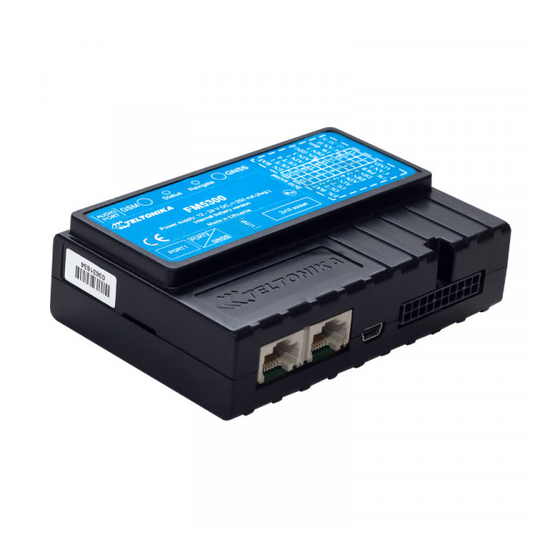
Storage relative humidity 5 … 95 % Socket 2x10 or similar (non condensating) Mini USB socket Port1 RS232 port channel 1 (RJ45 socket) Port2 RS232 port channel 1 (RJ45 socket) Audio port Figure 1 FM5300 view & dimensions in mm (tolerance ±2mm) -
Page 11: Technical Information About Internal Battery
In sleep mode a new FM5300 device, operating time approximately 15 hours In deep sleep mode – 137 hours Operating time for a new FM5300 device, working in normal mode (records are being acquired every 10 sec. and sent in packets of 4 records every 60 sec.), is approximately 2 h 30 min. -
Page 12: Electrical Characteristics
Electrical characteristics Table 2 Electrical characteristics VALUE Min. Typ. Max. Unit CHARACTERISTIC DESCRIPTION SUPPLY VOLTAGE Supply Voltage (Recommended Operating Conditions) 11.8 Supply Voltage (for internal rechargeable battery charging proper 11.8 functioning) POWER SUPPLY CURRENT (HARDWARE VERSION WITH INTERNAL BATTERY) Deep Sleep, average, Icc.ds Sleep, average, Icc.ds, Vcc=12V Sleep, average, Icc.ds, Vcc=24V Ucc=12.6V, all modules fully working, internal battery is... - Page 13 Common mode input voltage When connecting a COM port to an active external device keep in mind that the first power supply must be connected to FM5300, and then the external device should be powered. Connecting external devices when FM5300 is powered off is not recommended.
-
Page 14: Absolute Maximum Ratings
Analog Input Voltage (Absolute Maximum Ratings) Voltage on Supply Voltage 1-Wire (Absolute Maximum Ratings) Voltage on Data Input/Output 1-Wire (Absolute Maximum Ratings) Voltage on CANH, CANL (Absolute Maximum Ratings) 4 CONNECTION AND PINOUT 4.1 SIM card insert scheme Gently open FM5300 case using screwdrivers... - Page 15 Take off FM5300 case and insert SIM card Assemble device as shown and put screws as shown into the holes ...
-
Page 16: Installing Fm5300 Drivers
Installing drivers Extract and run VCPDriver_V1.3.1_Setup.exe. This driver is used to detect FM5300 device connected to the computer. Click ‘Next’ in driver installation window (figures below): Figure 2 Driver installation window This will launch the device driver installation wizard. In the following window click ‘Next’... -
Page 17: Navigate Led
Setup will continue installing drivers and will display a window about successful process in the end. Click ‘Finish’ to complete setup: Figure 4 Driver installation window You have now installed drivers for FM5300 device successfully. 4.3 Navigate LED Table 4 Navigate LED operation... -
Page 18: Socket 2 10 Pinout
4.5 Socket 2 10 pinout (-)EXT. BAT (+) EXT. BAT OUT 2 OUT 1 OUT 3 OUT 4 AIN 2 AIN 1 AIN 4 AIN 3 DIN 2 DIN 1 DIN 4 DIN 3 1W. PWR 1W. data CAN L CAN H (-)GND (+)VCC (10 30)V DC... -
Page 19: Usb
– the internal accumulator is off. 4.6 USB When FM5300 is connected to a PC it creates a STM Virtual COM Port, which can be used as a system port (to flash firmware and configure the device). Figure 6 COM-Ports 4.7 Accessories... - Page 20 1 – Wire devices One of the FM5300 features is realized 1-Wire data protocol, which enables connection of up to three thermometers (DS1820, DS18S20 and DS18B20) and I-Button DS1990A see Figure 7 Digital thermometer DS1820 and TTJ 100 connection scheme. Figure 8 show FM5300 and 1-wire devices connection schemes.
- Page 21 Impulse counters Figure describes the connection scheme to the FM5300. Here two pulse meters are used, where one is mounted on the direct flow valve and the other on the return flow valve. Data from both meters is sent to the FM5300.
- Page 22 Figure 9 Pulse fuel meters connection scheme Alarm buttons, door sensors, etc Alarm buttons, door sensors, ignition, etc return two states: high or low voltage. Digital inputs should be used to read this information. Figure below shows how to connect alarm button, door sensor, etc.
- Page 23 Immobilizer relay When connected a shown below, FM5300 disables engine starter when output is ON. More details about relays can be found below. Figure 12 Immobilizer relay connection Relays A simple automotive relays is used to invert input signal or to immobilize engine starter.
-
Page 24: Firmware
See configuration description for details. Contact sales manager to get the latest firmware. Connect FM5300 to PC with USB cable. Launch “Firmware Updater”, select COM port, click connect and update. Update process may take up to several minutes. Figure 14 FM updater screen... -
Page 25: Operational Basics
FM5300 perform while in this mode can be found in chapter 10. 6.3 Accelerometer FM5300 has a built in 3 axis accelerometer which allows the device to indicate if vehicle is moving or not, as well as measure acceleration. Accelerometer sensitivity can be configured – it has 2 configurable global parameters: start and stop timeouts that define time intervals in seconds. -
Page 26: Virtual Odometer
Ext. Battery (+). When DIN disconnected from Ext. Battery (+)the call is triggered, FM5300 dials the number which is defined in “Call Number” field. To initiate a call to FM5300 dial a number of the SIM card that is inserted in FM5300. When FM5300 has an incoming call it can play a selected tone from the “Ringtone”... -
Page 27: Profiles
6.6 Profiles FM5300 has 4 profiles saved in Flash memory of the module. Every profile has a list of parameters, which enables FM5300 to operate in different modes while using different profiles. The easiest way to understand what is a profile is to compare it to a list of instructions that are written for different cases. -
Page 28: Trip
Next time before driving user has to disable Auto Geofencing with iButton or by turning on car ignition. In case of theft, the car leaves Auto Geofencing zone without authorization and FM5300 device automatically sends high priority record to AVL application. -
Page 29: Configurator Structure
FM5300 has four user editable profiles, which can be both loaded and saved to the device. User can also revert to default settings, by pressing Load Defaults button. After any modification of configuration settings it has to be saved to FM5300 device, otherwise it will not be written to device flash memory. -
Page 30: Buttons Area
Keyword is of 4 - 10 symbol length (Latin text and/or numbers). If a keyword is set, every time user reconnects FM5300 to USB or COM1 port he will be asked to enter a valid keyword when connecting FM5300 to... -
Page 31: Parameters Configuration
Figure 20 FM5300 Configurator profiles loading window After changing profile and global parameters, changes can be saved to FM5300 Flash. By pressing “Save” button all 4 profiles and Global parameters are saved to the Flash (Figure 21). - Page 32 Voice settings Allows to setup microphone sensitivity and speaker loudness level. Allows entering one number to which FM5300 will be able to call to. Call trigger defines input, which will be used to receive or make a call. Call Settings Usually to that input a button is connected (“Digital Input 1”...
-
Page 33: Settings And Configurable Parameters Menu
Allows configuring COM2 baud rate, parity mode, end line, binary COM2 Settings timeout and 3 prefixes. When two or three temperature sensors are connected to FM5300 it is necessary to define sensor ID to certain property separately. This way Temperature FM5300 will know which temperature sensor is which property. - Page 34 Ignition source settings, for choosing which ignition source prefer to use DIN1 or External Voltage. While using External Voltage must to set levels. Figure 23 System Settings Configuration When Vehicle Generator is working supply voltage is usually 2V – 4V volts higher than when it not.
-
Page 35: Gsm Settings
7.3.1.2 GSM Settings 7.3.1.2.1 GPRS ‘GPRS’ defines main parameters for FM5300: GSM operator APN and GPRS username and password (optional – depending on operator), destination server Domain (can be entered either IP or domain name) and port. Also both TCP and UDP protocols are supported. - Page 36 Essential fields in ‘SMS’ part is ‘Login’ and ‘Password’ (Figure 25). This login and password is used with every SMS sent to FM5300. If login and password are not set, every SMS sent to FM5300 device has to include two spaces before command (<space><space><command>).
-
Page 37: Operator List
Teltonika sale manager to find out more about protocols documentation purchase. 7.3.1.2.4 Operator List FM5300 is able to use GPRS with all operators but if at least one operator is entered in the list, FM5300 is allowed to connect to GPRS only while operating in listed operator’s network. Also operator list has influence on profile switching (see details in chapter 7.1) if Global parameter... -
Page 38: Features
7.3.1.3 Features 7.3.1.3.1 Mode FM5300 is able to collect records using three methods at the same time: time, distance and angle based data acquisition (chapter 9). Send and Save Parameters configuration is available in Features->Mode category (Figure 28): Min Period – time period change that initializes record save. - Page 39 Figure 28 FM53 Features->Mode Configuration...
-
Page 40: Scenarios
7.3.1.3.2 Scenarios In Scenarios window four different scenarios are available, two per each Digital Output (DOUT). Only one per digital output can be active at a same time, e.g. DOUT1 can have either ECO driving/Green driving/Green driving or Over Speeding enabled, DOUT2 can have either Authorized Driving or Immobilizer enabled. -
Page 41: Geofencing
Trip period. 7.3.1.3.4 Geofencing 7.3.1.3.4.1 Geofencing settings FM5300 has 20 configurable Geofence zones and it can generate event when defined Geofence zone border has been crossed. Figure 31 FM53 Features->Geofencing Configuration (1) -
Page 42: Autogeofencing Settings
Frame border – frame border is an additional border around Geofence zone. It is additional area around defined zone used to prevent false event recording when object stops on the border of the area and because of GPS errors some records are made inside area and some –... - Page 43 Figure 33 FM53 Features->Autogeofencing Configuration AutoGeofencing option can be configured by following parameters visible in Figure 33 below. Activate – Enable or Disable AutoGeofence functionality. Activation TMO – Time period before Geofence is activated after vehicle stops. ...
-
Page 44: Ibutton List
If all I/O elements are disabled AVL packet comes with GPS information only. After enabling I/O element(s) AVL packet in couple with GPS information contains current value(s) of enabled I/O element. 7.3.1.4.1 FM5300 available I/O list Table 9 PERMANENT I/O elements list description Permanent I/O elements... - Page 45 Permanent I/O elements (are always sent (with every record) to server if enabled) Property Name Bytes Description Dallas Temperature 1 10 * Degrees ( °C ), -55 - +115, if 3000 – Dallas error Dallas Temperature 2 10 * Degrees ( °C ), -55 - +115, if 3000 – Dallas error Dallas Temperature 3 10 * Degrees ( °C ), -55 - +115, if 3000 –...
- Page 46 Eventual IO elements (generated and sent record to server only if appropriate conditions are met) Property Name Bytes Description CAN 7 Varying ID Specific data CAN 8 Varying ID Specific data CAN 9 Varying ID Specific data Geofence zone 01 Event: 0 –...
-
Page 47: I/O Configuring
By default, all I/O elements are disabled and FM5300 records only GPS information. It is also possible to set CAN message instead of any I/O element – this way CAN element will be sent to the server instead of chosen element. -
Page 48: I/O Properties
DESCRIPTION SW2X priorities switch profiles on event (SW21 – Profile 1, SW22 – Profile 2 and so on). High Level – define I/O value range. If I/O value enters or exits this range, FM5300 generates event. Low Level – define I/O value range. If I/O value enters or exits this range, FM5300 generates event. - Page 49 I/O#0 Low level (ID=303) I/O#0 logic operand (ID=304) I/O#0 averaging constant (ID=305) I/O#0 priority (ID=301) Parameter defines I/O property type of priority: 0 is low, 1 – high, 2 – panic, 3 – empty, 4 – SW21, 5 – SW22, 6 – SW23, 7 –SW24. Table 14 I/O Type of Priority Minimum Maximum...
- Page 50 Table 17 I/O Logic Operand Minimal Maximum Recommended Goes with (depends on) Value value value value parameters type I/O#0 priority (ID=301) I/O#0 High level (ID=302) I/O#0 Low level (ID=303) I/O#0 averaging constant (ID=305) I/O#0 property parameter (ID=300) I/O#0 averaging constant (ID=305) Parameter defines I/O property sample length to average.
-
Page 51: Can
I/O#12 – Fuel 420 – 425 I/O#29 – Dallas Temp. 1 590 – 595 temperature 1 I/O#13 – Fuel level meter 430 – 435 I/O#30 – Dallas Temp. 2 600 – 605 I/O#14 – Fuel 440 – 445 I/O#31 – Dallas Temp. 3 610 –... - Page 52 Table 22 Output data mask Minimum Maximum Recommended Goes with (depends on) Value type value value value parameters CAN#0 CAN Type ID (ID=770) CAN#0 CAN ID (ID=772) CAN#0 CAN ID (ID=772) Parameter defines CAN identifier. ID can be 11 or 29 bits length. Example: 18FEE925 (total fuel used) Table 23 CAN ID Minimum...
-
Page 53: Configurable Parameter Values And Global Parameter Values
7.3.1.6 Configurable parameter values and Global parameter values 7.3.1.6.1 Configurable parameters Table 25 Configurable parameter values Parameter value Parameter Recommend Value type Default System parameters (chapter 7.3.1.1) Sleep Mode (0 – disable, 1 – enable, 2 – Deep Sleep) Sleep Timeout 9000 Data Acquisition parameters (chapter 9) Min Period (in... - Page 54 Zone #1 Latitude Y2 Float (Rectangle) / None (Circle) AutoGeofencing parameters (chapter 7.3.1.3.4.2) Deactivate By 0 (Ignition) 1 (iButton) Enable/Disable 0 (Disable) 1 (Enable) Activation Timeout 65535 (in seconds) Priority (0 – Low, 1 – High, 2 – Panic, 4, 5, 7 (exl.
- Page 55 Output Duration Digital Output No.2 usage scenarios OverSpeeding (0 – disable, 1 – enable) Trip Start/Stop Detection (0 – disable, 1 – enable) Start Speed Ignition Off Timeout 65536 Trip Continuous Distance Counting (0 – not, 1 – continuous) Manual CAN Can Baud rate 1000 Autobaud(0)
-
Page 56: Global Parameters
SMS data sending settings (0 – disable, 1 – enable) SMS Login Empty 5 char Empty S8[5] SMS Password Empty 5 char Empty S8[5] Authorized phone 260- Empty 16 char Empty S8[17] numbers Operator Code 99999999 SMS Data send Binary Binary 20 byte array week time schedule... -
Page 57: Read Records* (* New Functionality Available With Fm5300M Version)
When the FM5300M is working in offline mode, it can save over 45,000 records. Since these records are not sent to the server, they can be downloaded directly to computer using USB connection. When FM5300 connected to configurator appears additional option “Read Records” (Figure 30). - Page 58 Figure 36 FM53XX Configurator window with FM53M connected After device is switched on, you have to wait 3 minutes for device to startup. Only then it is possible to download records. If the memory is fully filled, reading may take several minutes. All records are deleted from device’s memory after reading.
- Page 59 More details on how to use TAVL application please refer to “TAVL3 application user manual v1.4” documentation or its latest versions. FM53M version can be still used as a standard FM53. It can be configured to acquire and send data to server. It will be possible to store up to 47,615 data records if GSM is not available at the moment.
-
Page 60: Profile Switching
4 profiles. This means that if you set FM5300 to call to a predefined number, you will be able to call it while using any profile. Basic scheme of Global parameters and profiles is shown below. According to the scheme, every profile has a list of parameters. - Page 61 If there are no operator codes entered in all profiles after operator search task FM5300 will check all 3 profiles and won’t find any operators in any list. In such a case, FM5300 will switch to profile 3. Note that before switching to profile 3, the device closes the GPRS session.
-
Page 62: Profile Switching Dependence On I/Oevent
Figure 39 GSM Operator code profile switching (…) 8.2 Profile switching dependence on I/O event Another profile switch method is based on I/O event. Events happen when the value of enabled I/O intersects thresholds (enter, exit, on both, hysteresis) predefined by High and Low... -
Page 63: Example #1
SW21, SW22, SW23, SW24 stands for “Switch to profile No. X”. After an event happens, FM5300 switches to a defined profile. Using profile switching you can create smart applications. SW2X actions can be performed only if “Profile change on event” is enabled in Global parameters. -
Page 64: Data Acquisition
Figure 42 Switch to profile on event (2) 9 DATA ACQUISITION Data can be acquired using GPS or I/O elements. GPS data is for basic vehicle tracking, data acquisition by I/O elements gives more specific information. 9.1 GPS data acquisition There are three ways of GPS data acquisition which are configured in Features >... -
Page 65: Min. Period
Min. Period Time based data acquiring (Figure ) – records are being acquired every time when Figure 44 defined interval of time passes. Entering zero means that data will not be recorded according to time. This method is suitable best for basic position update. Min. -
Page 66: I/Odata Acquisition
9.2 I/O data acquisition Data also can be acquired using input output elements (it’s change). All base elements are declared in Table 9 PERMANENT I/O elements list description and in Table 10 EVENTUAL I/O elements list description Configuration Data acquisition by I/O elements can be configured selecting I/O menu in configurator (refer to chapter 7.3.1.4.2). -
Page 67: Sleep/Deep Sleep Modes
10 SLEEP/DEEP SLEEP MODES SLEEP MODE FM5300 is able to go to sleep mode after configurable Sleep timeout. This timeout (defined period) starts counting when device is in STOP mode. After timeout is reached and all conditions for sleep mode are met, device goes to sleep mode. -
Page 68: Deep Sleep Mode
Note: If there is no need to save or send periodical data FM5300 has to be configured to switch to another profile on Deep Sleep Event where Min Period and Send Period parameters are 0 or big enough. -
Page 69: Features And Scenarios
To save GPRS traffic ECO driving/Green driving event will be generated (included into records) only when FM5300 measured values are higher than those set in configuration, without additional I/O settings. To prevent generating false events, harsh acceleration and harsh braking is monitored only... -
Page 70: Mounting Requirements
(Figure 52) mounting recommendations are displayed. Please note that beside those recommendations 1. You can choose how FM5300 is deployed. It means that that there is no effect to measurements if FM5300 top/bottom side points up or down. 2. Device can be deployed at any place in the car. - Page 71 Deviations of maximum +/- 15 are allowed (Figure 53). Figure 53 MAX deviation from horizontal plane of FM5300 mounting Figure 54 Horizontal position MAX deviation of FM5300 mounting Horizontal position must be as flat as possible – parallel with vehicle plain.
-
Page 72: Configuration
Configuration Parameters used with ECO driving/Green driving functionality. Figure 55 ECO driving/Green driving configuration parameters Table 27 ECO driving/Green driving parameters description ECO driving/Green driving configuration Description parameter name ECO driving/Green Enable/Disable ECO driving/Green driving functionality driving Value which can be reached while accelerating without triggering harsh Max Acceleration Force acceleration event. -
Page 73: Overspeeding Scenario
If any of three cases are satisfied event is generated. Record is saved and sent to server (FM5300 must be configured properly). Event value is multiplied by 10 before sending/saving record to get more precision when displaying data*. -
Page 74: Immobilizer Scenario
Figure 58 Authorized driving configuration parameters Authorized Driving. Enable/Disable Authrized Driving. Edit iButtons List. Enter authorized iButtons 11.5 COM1 and COM2 Working Modes Silent Mode FM5300 doesn’t do any activity in silent mode. Logs aren’t saved and any data isn’t sent. -
Page 75: Fm Log Mode
FM Log Mode This is default mode of the FM5300. It is suitable for debugging. LLS Mode 11.5.1.1 LLS Mode Configuration 1. Globals->COM1 Settings->Baudrate = 19200 2. Globals->COM1 Settings->Mode = LLS 3. Globals->COM2 Settings->Baudrate = 19200 4. Globals->COM2 Settings->Mode = LLS... -
Page 76: Multipacket Support
Multipacket support With multipacket support FM53 can put two or more smaller input strings in one bigger special packet . Packet. This reduces possibility to miss packets from uart. Example: Input String: Hello$0aHello$0aHello$0a Without Multipacket server will see: Hello$0a With Multipacket server will see: Hello$0aHello$0aHello$0a LCD Mode Configuration 1. -
Page 77: Rfid Mf7 Mode Configuration
RFID MF7 Mode Configuration 1. Globals->COM1 Settings->Baudrate = 9600 2. Globals->COM1 Settings->Mode = RFID MF7 1. Globals->COM2 Settings->Baudrate = 9600 2. Globals->COM2 Settings->Mode = RFID MF7 3. Globals->COM2 Settings->Parity = None Garmin Mode Configuration 11.5.1.3 Settings 1. Globals->COM1 Settings->Baudrate = 9600 2. -
Page 78: Firmware Configuration
11.5.1.4 Firmware Configuration Supported Garmin protocols: A*** (http://developer.garmin.com/lbs/fleet-management/fmi-protocol-support-matrix/) Blocked Garmin ID’s: Command 0A Date/Time Data 0E Unit ID/ESN 26 Pvt Data 33 Legacy Stop Message 87 Legacy Text Message 88 Ping 0260 Ping response 0261 Product ID Request 0001 Product ID Data 0002 FM send ACK the these packets, ant these packets are not sent to server to reduce traffic. -
Page 79: Tcp Link Mode (Binary)
TCP Link Mode (Binary) This mode is the same as above but binary message will be accepted to/from COM port. This mode also have some advanced filtering capabilities. 1. Globals->COM2 Settings->Baudrate = any of available baudrates 2. Globals->COM2 Settings->Mode = TCP Link Mode 3. -
Page 80: Sms Command List
12 SMS COMMAND LIST SMS commands are used to identify FM5300 current state, possible configuration errors, perform reset, set parameters, switch on/off outputs, etc. SMS commands should be sent along with module login and password and sender number must be entered in the authorized number list (if at least one other number is entered). Please see SMS settings in chapter 6.3.2.2.2 for more details. -
Page 81: Getstatus
setparam # # Set parameter value according entered ID and Value. 1.# - ID value. 2.# - New Parameter Value flush Initiates all data sending to specified target server #,#,#,#,#,#,# 1.# - IMEI 2.# - APN 3.# - LOGIN 4.# - PASS 5.# - IP 6.# - PORT 7.# - MODE (0-TCP/1-UDP) -
Page 82: Getops
Table 30 getweektime Response details Description Clock Sync Indicates system clock synchronization status. 0 – System is not synchronized, 1 – System synchronized Day Of Week – indicates current day of week starting from 1 – Monday, 2 – Tuesday, etc. Time Indicates current GMT time WeekTime... -
Page 83: Getgps
Date/Time Returns last performed configuration date and time. Answer Example: Last Configuration was performed on: 2010.4.15 5:45:19 12.7 getgps Table 35 getgps Response details Description Indicates valid (1) or invalid (0) GPS data Count of currently available satellites Latitude (Last good Latitude) Long Longitude (Last good Longitude) Altitude, m... -
Page 84: Getio
Hardware type Answer Example: Code Ver:01.02.12 Rev:1 Device IMEI:353976010139156 Device ID:000007 BL Ver:05.16 Modem Ver:TM11Q_R_01.03.04.00_004 Hw:Int Bat + GGG + LIS3DH 12.12 getio Table 37 getio Response details Description Digital Input state Digital Output state Analog Input state Answer Example: DI1:0 DI2:0 DI3:0 DI4:0 AI1:0 AI2:0 AI3:0 AI4:0 DO1:0 DO2:0 DO3:0 DO4:0 12.13 getinfo Table 38 getinfo... -
Page 85: Deleterecords
12.14 deleterecords Deletes all saved records from device memory. Device does not send a response back to the sender. 12.15 readio # Table 39 readio # Response details Description IO element ID Value IO Element value Answer Example: IO ID:3 Value:0 12.16 setdigout #### X Y Z W Sets digital outputs to ON or OFF state (for some time if needed). -
Page 86: Flush
12.19 flush #,#,#,#,#,#,# Initiates all data sending by GPRS to specified target server. Comma separated parameters go as numbered: 1.# - IMEI 2.# - APN 3.# - GPRS LOGIN 4.# - GPRS PASSWORD 5.# - IP 6.# - PORT 7.# - MODE (0-TCP/1-UDP) Parameters are separated by comma (no spaces needed). -
Page 87: Banlist
Returns state of static navigation and previous state: Static Nav is Disabled. Was:X or Static Nav is Enabled. Was:X ( 1 – enabled, 0 – disabled). If sent X is not 0 or 1, then response is: WARNING: Undefined SN parameter: X 12.22 banlist Returns a list of possible banned operators. -
Page 88: Getcontsens
Continuous Movement Not moving moving GPS: GPS Module Status 0-OFF 1-Restarting 2-Ready no FIX 3-Working FIX 4-Sleep FIX: GPS FIX No FIX Valid: Valid Nmea data Not Valid Valid GPS Speed [0-350] Nmea Stable Flag 0 – Not Stable 1 –Stable Jump Lock Lock ON Lock OFF... -
Page 89: General Description
SAE J1939 is the vehicle bus standard used for communication and diagnostics among vehicle components. Based on the same architecture FMS protocol dedicated to telematics systems is available. It has certain standardized parameters available, such as fuel consumption, engine work-hours, etc. Please visit http://www.fms-standard.com/ for more information and message structure. -
Page 90: Configuration
Figure 61 CAN baud rate configuration window Note that If FM5300 is set to “Autobaud” mode it will always check for CAN network even if device isn’t connected to any of it. CAN message ID type: Message ID type (Figure 62 CAN message ID types6) two types according to SAEJ1939 standard: Standard ID (value: 0 to 0x7FFh) and Extended ID (value: 0 to 0x1FFFFFFFh). -
Page 91: Example
All Mercedes Benz Actros 2 models with Vehicle Identification Number (VIN) starting with WDB93 have a possibility to connect FM5300 module to CAN bus. This can be done by connecting to special PSM module (which may or may not be included in the truck) or ground module of the vehicle. - Page 92 Figure 64 X5 plug on Mercedes Benz In the example FM5300 will filter all CAN messages with identifier FFFEE9FF (fuel consumption) (Figure 65). Figure 65 CAN parameter configuration example Note: Averaging constant cannot be used with CAN data, because this information comes in digital format.
- Page 93 The example indicates how fuel consumption message is selected and how configuration impacts this selection (Figure 66). Figure 66 Example When certain message is filtered, FM5300 checks which data bytes should be sent to server. Document indicates that 5-8 bytes are used in FMS standard.
-
Page 94: Autocan Description
AutoCAN function allows user to automatically scan for available messages on CAN bus and configure CAN data sending to server. In order to configure AutoCAN connect FM5300 to computer with Port ½ cable. Launch FM53xx configurator version 1.1.1.7 or higher. Push “Connect“... -
Page 95: Configuration
Figure 68 Entering CAN configuration SCAN scans once for available messages on CAN bus; Monitoring – toggles scanning of messages on CAN bus every 3 seconds; Offline Configuration – enables CAN configuration when FM53xx is not connected to CAN bus; Auto CAN tab –... -
Page 96: Can Monitoring
o Hysteresis – record is generated when increasing parameter value becomes higher than High value, and decreasing becomes less than Low value o Event on exit – record is generated when parameter value becomes higher than High value or lower than Low value; o Event on entrance –... -
Page 97: Offline Configuration
Configuration section. Offline configuration When FM5300 device is not connected to CAN bus you can configure CAN data sending by pushing “Offline configuration” button. When offline configuration is enabled a configuration table of all FMS standard CAN data is shown. - Page 98 More info. 65260 – Vehicle Vehicle Max 24 U8[24] [105- Max 24 ASCII Identification identification 107] bytes. number More info. SW-version U8[4] 4 ASCII bytes. 2806 supported More info. 64977 – FMS Standard Diagnostics [0-3]. 2804 interface supported More info. Requests [0-3].
- Page 99 More info. 64932 – PTO Drive At least one PTO [0-3]. 3948 Engagement engaged More info. 64777 – High High resolution [0–4,211,081] 5054 Resolution Fuel engine total fuel (liter). Consumption (Liquid) used More info. Brake switch: Switch signal which indicates that the driver operated brake foot pedal is being pressed. This brake foot pedal is controlling the vehicles’...
- Page 100 Data Length: 2 bits Resolution: 4 states/2 bit, 0 offset Data Range: 0 to 3 Operational Range: same as data range Type: Measured Supporting information: PGN 65265 Note: Firmware captures only [0,1] values. [2,3] – are ignored. Clutch switch: Switch signal which indicates that the clutch pedal is being pressed. It is necessary for a safe drivetrain behavior that the clutch switch is set before the clutch is opened (cruise control function).
- Page 101 01111 Preprogrammed set speed 6 10000 Preprogrammed set speed 7 10001 Preprogrammed set speed 8 10010 PTO set speed memory 1 10011 PTO set speed memory 2 10100-11110 not defined 11111 Not available Off/Disabled 00000b — Used to indicate that the PTO governor enable switch is in the off position.
- Page 102 Preprogrammed PTO Governor Set Speed 6 01111b—used to indicate that the remote PTO device is establishing a sixth preprogrammed PTO governor set speed (user programmable) as the current operating speed. Preprogrammed PTO Governor Set Speed 7 10000b —used to indicate that the remote PTO device is establishing a seventh preprogrammed PTO governor set speed (user programmable) as the current operating speed.
- Page 103 Resolution: 1 %/bit, 0 offset Data Range: 0 to 250 % Operational Range: 0 to 125% Type: Status Supporting information: PGN 61443 Note: Since bitgain is 1%/bit – raw data is sent to server. But, data is limited to max 125 (0x7D). If captured data is higher than 125 (decimal) - data is truncated to 125.
- Page 104 Axle weight: Total mass imposed by the tires on the road surface at the specified axle. Data Length: 2 bytes Resolution: 0.5 kg/bit, 0 offset Data Range: 0 to 32,127.5 kg Operational Range: same as data range Type: Measured Supporting information: PGN 65258 Note: Value sent to server is already adjusted with bitgain.
- Page 105 Byte 2 and byte 3 represents the SW version supported for trucks. Version number in the format ab.cd where Byte 2 represents "a" ASCII and Byte 3 represents "b" ASCII. Byte 4 and byte 5 represents the SW version supported for bus and coaches; version number in the format ab.cd where Byte 4 represents "c"...
- Page 106 10 Reserved 11 Don't care Data Length: 2 bits Resolution: 4 states/2 bit, 0 offset Data Range: 0 to 3 Operational Range: same as data range Type: Status Supporting information: PGN 64977 Note: Firmware captures all values [0x00-0x03]. High resolution total vehicle distance: Accumulated distance traveled by the vehicle during its operation.
- Page 107 PGN 65132 Note: Firmware captures all values [0x00-0x03]. Driver 1/2 working state: State of work of the driver. 000 Rest - sleeping 001 Driver available – short break 010 Work – loading, unloading, working in an office 011 Drive – behind wheel 100-101 Reserved 110 Error 111 Not available...
- Page 108 Supporting information: PGN 65132 Note: Firmware captures all values [0x00-0x03]. [0x00-0x03] range is valid for all FM5300 FW and FM5302 until and including 01.02.10.Rev.00. Since FM5302.01.02.10.Rev.01 only these values are taken [0x00-x02]. I.e. not available state is ignored. Direction indicator: Indicates the direction of the vehicle.
- Page 109 Indicates the tachograph performance; including electronic or mechanical analysis, instrument analysis, speed sensor analysis, mass storage analysis, and printer analysis. 00 - Normal performance 01 - Performance analysis 10 - Error 11 - Not available Data Length: 2 bits Resolution: 4 states/2 bit, 0 offset Data Range: 0 to 3 Operational Range: same as data range Type: Status Supporting information:...
- Page 110 Tachograph vehicle speed: Speed of the vehicle registered by the tachograph. Data Length: 2 bytes Resolution: 1/256 km/h per bit, 0 offset Data Range: 0 to 250.996 km/h Operational Range: same as data range Type: Measured Supporting information: PGN 65132 Note: Since FM FW sends this parameter as U16 (2 Bytes), value after floating point is discarded.
- Page 111 server (129,130), and if driver ID length > 16 and <= 24 then three IO ID’s will be sent to server (129,130,131). Engine fuel rate: Amount of fuel consumed by engine per unit of time. Data Length: 2 bytes Resolution: 0.05 L/h per bit, 0 offset Data Range: 0 to 3,212.75 L/h Operational Range: same as data range Type: Measured Supporting information:...
-
Page 112: Autocan Configuration Over Sms
13.5 AutoCAN Configuration over SMS SMS command format: “<login><space><password><space>setparam<space><Parameter ID><space><value>” if there is no login and password configured in FM configuration, 2 spaces must be used before command : <space><space><command>. Parameter ID explanation: 20090 digit represents Profile number. digit is not used. and 4th digits represents AutoCAN element ID. -
Page 113: Autocan Element Parameters
65216 - Service Information Service distance 65132 - Tachograph Vehicle motion X driver 2 working state X driver 1 working state X Vehicle overspeed Driver 1 time rel. states Driver 2 time rel. states Driver 1 card X Driver 2 card X Direction indicator Tachograph performance X Handling information X... -
Page 114: Example Of Autocan Parameter Configuration Over Sms
Figure 72 RFID I/O parameter To set up FM5300 so it can be connected to an RFID reader, Global parameters have to be set up. Go to Global parameters and set up COM1 or COM2 settings to RFID Mode or RFID MF7 Mode (the used mode depends on the mode that the RFID reader works). -
Page 115: Garmin
COM2. Figure 73 RFID Global parameter settings The difference between RFID Mode and RFID MF7 Mode is that in RFID Mode FM5300 understands RFID messages that are in hexadecimal format and RFID MF7 Mode understands messages that are in decimal format. For example: RFID Mode message –... -
Page 116: Supported Garmin Fmi Protocols
The following is a list of protocols supported and the corresponding feature/benefit. FM5300 can fully support Fleet Management Interface (FMI) versions up to 2.1. Other or higher versions may be supported, but Teltonika is not responsible for the changes made by Garmin, which may affect the work of FM5300 and Garmin products. -
Page 117: Enhanced Protocols
• Garmin can also provide confirmation that driver has received a particular Stop, read the details, or deleted it from list. • Can provide confirmation that a Stop has been completed. Estimated Time of Arrival Protocol: • Dispatcher/office can request the ETA of the current stop/job in progress. •... -
Page 118: Destination Message
Figure 75 RJ45 Pinouts In order to connect Garmin PND to FM5300, Garmin mode has to be set in Global parameter settings ( Figure 76 ). Simply choose Garmin mode in either COM1 or COM2 settings mode, but you cannot activate Garmin mode in both ports at the same time. -
Page 119: Lls Sensor
5.zip. Software version updates: http://www8.garmin.com/support/download.jsp. For more information about Garmin PND device connectivity to FM5300 and additional information, please contact to your local sales representative. 15 LLS SENSOR LLS sensor series liquid level sensors are solid-state capacitive devices with no moving parts. -
Page 120: Specifications
Figure 77. Figure 77 FM5300-LLS fuel sensor connection scheme RJ-45 male plug *Teltonika is not responsible for any changes made by the manufacturer, which is not declared in fuel level sensor documentation. Then FM5300 must be configured. Both fuel level and fuel temperature has to be set up by... - Page 121 Enable ID11 and ID12, or ID13 and ID14, or all four I/O elements (Figure 78) at the same time because two LLS sensors can be connected to FM5300 at the same time (for example if a vehicle has two fuel tanks).
- Page 122 When two LLS sensors are connected the same is applied, but it is possible to enter the polynomials into the configuration of FM5300 and it sends the sum of both LLS sensors, but the data sent is already in liters so no additional calculations have to be made on the server.
- Page 123 Then, enter these values in Excel and calculate another value N+, according to the formula: FM5300 converts the read data using this formula, so we need to have the converted values also. Next, enter the new values in Excel and create a scatter chart, like in Figure 80.
- Page 124 Figure 81 Adding a trendline Select a polynomial type of 5 order trendline. Also select “Display equation on chart” checkbox (Figure 82).
- Page 125 Figure 82 Selecting polynomial order A new line appears alongside the created one, as well as a formula for that new line (Figure 83).
- Page 126 Here, the polynomials a0…a5 have to be written in the polynomial calculation on the server. If it is required for FM5300 to send the data in liters, these polynomials can be written in the configuration of the device. To do this, go to global settings, and choose both ports to work in LLS mode (Figure 84).
- Page 127 “Write Polynoms”: Figure 85 LLS sensor advanced (polynomial) setup After the configuration is saved successfully FM5300 is ready to send measured fuel level. For additional information about LLS sensors, their configuration and connectivity to...
-
Page 128: Gprs Commands
It is possible to send commands to FM5300 using GPRS. When FM5300 sends records periodically to a server, a message could be sent from the server and FM5300 will reply to it. FM5300 has to be connected to the server in order to receive commands. - Page 129 #GET REMIPX Get IP and port number from the configuration of a certain profile, X – profile #SET REMIPX=Y:Z Set IP and port number to the configuration of a certain profile, X – profile no, Y – IP or domain, Z – port number #GET AUPX Get APN, user login and password from the configuration of a certain profile, X –...
- Page 130 getcfgtime Date and Time of last successful configuration getgps Current GPS data and time loadprofile# Load specified profile into RAM Engine Profile. # - number of profile to load cpureset Reset CPU resetallprof Reset all FLASH profiles to default profile getver Device / Modem / Code version information getinfo...
-
Page 131: Debug Mode
17 DEBUG MODE FM5300 is able to transmit its current state when connected to PC using PORT1/2 cable. It is used to detect errors and provide information to possible solutions when operating as unexpected. Contact our sales manager to get Terminal. After launching it choose baud rate 115200 and hardware control –... - Page 132 To read offline log log2srvstart command is used. It sends log to earlier preconfigured server (log2srv). Offline log sending also can be terminated using log2srvstop command. COMMANDS “SMSlogin<space>SMSpassword<space>log2srv<space><enable>,<mode>,<APN>,<userna me>,<password>,<IP>,<port>,<TMO>,<Log mode>” o <enable> - enable (1), disable(0); o <mode> - silent (0) – connect to server and send “Hello” message (all “Terminal” commands can be used) ...
- Page 133 Example: opa opa log2srv 1,3,banga,,,212.47.99.62,7092,300,0 Note: Up to 5 minutes delay could appear if wrong “log2srv” commands settings will be sent, during that time no SMS or GPRS command could be received. SMS will be hanging, after timeout, hanging SMS’s will be proceeded. Function have: FM53.Ver.01.02.XX DOWNLOADING LOG USING “HERCULES”...
- Page 134 2 STEP Set directory for file download Enable “Log to file” as show below 3 STEP “Terminal” Command sending using Hercules...
-
Page 135: Mounting Recommendations
19 MOUNTING RECOMMENDATIONS 19.1 Connecting Wires Wires should be connected while module is not plugged in. Wires should be fastened to the other wires or non-moving parts. Try to avoid heat emitting and moving objects near the wires. The connections should not be seen very clearly. If factory isolation was removed while connecting wires, it should be applied again. -
Page 136: Connecting Ground Wire
Ignition is connected to the ignition relay output. As alternative, any other relay, which has power output, when ignition is on may be chosen. 19.4 Connecting Ground Wire Ground wire is connected to the vehicle frame or metal parts that are fixed to the frame. If the wire is fixed with the bolt, the loop must be connected to the end of the wire. -
Page 137: Module Installation
19.6 Module Installation Module should not be seen or easily reached. Module should be firmly fixed to the surface or cables. Module cannot be fixed to heat emitting or moving parts. SIM card should be inserted in the module while the connector is plugged off (while module has no power). - Page 138 2012-11-27 CAN ID correction 2012-11-30 FM5300M support added 2013-03-27 Revised calculations of LLS polynomial 2013-05-22 Added FM5300 Remote log and Data limit functionality descriptions. 2013-06-05 Corrected default values of global parameters, added Garmin multipacket parameter. 2013-07-18 Updated I/O settings 2013-08-16...
- Page 139 Edited SMS commands example answers: getops; readops; getnmeainfo; braninfo Edited min/max parameters values for: ID 302; ID 303; ID 305; ID 013; ID 918; ID 919; ID 920; ID 109 2014.12.16 3.34 LLS ID 201 was changed to ID 203. Page 113. This solution is working only on FW version 01.07.16 and higher.
Need help?
Do you have a question about the FM5300 and is the answer not in the manual?
Questions and answers