Table of Contents
Advertisement
Quick Links
https://wiki.teltonika-gps.com/view/FMB641_First_Start
FMB641 First Start
Main Page
>
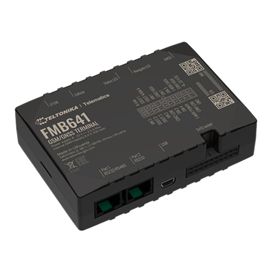
Professional Trackers
Leading GSM/GNSS Terminal for advanced applications
Contents
1 How to insert SIM card and connect the battery
How to insert SIM card and connect the battery
1.
Unscrew 4 screws counterclockwise that are located on the bottom of the device.
2.
Remove the cover.
Insert SIM card as shown with PIN request disabled or read
3.
later in
Teltonika
SIM slot 1 is closer to PCB, SIM slot 2 is the upper one.
Connect battery as shown to device.
4.
5.
After configuration, see
6.
Screw in all screws. Device is ready to be mounted.
SIM card insertion/removal must be performed when device is powered off – external
voltage and internal battery disconnected. Otherwise SIM card might be damaged or device
will not detect it.
>
FMB641
> FMB641 First Start
Configurator. Make sure that SIM card cut-off corner is pointing outside.
"PC Connection
(Windows)", attach device cover back.
Security info
how to enter it
Advertisement
Table of Contents

Related Manuals for Teltonika FMB641


Summary of Contents for Teltonika FMB641
- Page 1 Leading GSM/GNSS Terminal for advanced applications Contents 1 How to insert SIM card and connect the battery 2 How to insert microSD card into FMB641 3 2x10 socket pinout 3.1 PC Connection (Windows) 3.2 How to install USB drivers (Windows) 3.3 Configuration (Windows)
- Page 2 When 2 SIM cards are used simultaneously risk is mitigated as well - when SIM1 is inserted, a greater pressure is applied for SIM2, so SIM parts are harder to come lose How to insert microSD card into FMB641 Push microSD card lock case.
- Page 3 K-LINE K-LINE interface for online Tachograph Vehicle Data transfer PC Connection (Windows) Power-up FMB641 with DC voltage 8-32 V power supply using supplied power cable. LED’s should start blinking, see “FMB641 LED status”. Connect device to computer using Mini-USB cable connection and install USB drivers, see "How to install USB drivers...
- Page 4 Setup will continue installing the driver and eventually the confirmation window will appear. Click Finish to complete the setup. Note: on Windows 7 systems, an additional driver for FMB641 support must be installed. Driver can be found here. Configuration (Windows) At first FMB641 device will have default factory settings set.
- Page 5 Various and etc. FMB641 has one user editable profile, which can be loaded and saved to the device. After any modification of configuration the changes need to be saved to device using Save to device button. Main buttons offer following functionality: Load from device –...
- Page 6 If device has made a record it is sent to the server every 120 seconds After successful SMS configuration, FMB641 device will synchronize time and update records to configured server. Time intervals and default I/O elements can be changed by using Teltonika Configurator parameters.
- Page 7 GND vehicle computer. Connecting the GND at an arbitrary point to the mass of the car is unacceptable, as static and dynamic potentials on the line GND will be unpredictable, which can lead to unstable FMB641 operation and even its failure.
- Page 8 The device must be firmly fastened in a predefined location. The programming must be performed using a PC with autonomic power supply. The device is susceptible to water and humidity. Installation and/or handling during a lightning storm is prohibited. https://teltonika-gps.com/product/fmb640...
Need help?
Do you have a question about the FMB641 and is the answer not in the manual?
Questions and answers