Teltonika FMC125 Quick Manual
Advanced lte terminal with gnss and lte/3g/gsm connectivity, rs485/rs232 interfaces and backup battery
Hide thumbs
Also See for FMC125:
- Quick manual (21 pages) ,
- First start-up quick start manual (8 pages) ,
- Manual (3 pages)

Related Manuals for Teltonika FMC125


Summary of Contents for Teltonika FMC125
- Page 1 FMC125 Quick Manual Advanced LTE terminal with GNSS and LTE/3G/GSM v1.0 connectivity, RS485/RS232 interfaces and backup battery...
-
Page 2: Table Of Contents
How to install USB drivers (Windows) ..........7 Configuration (Windows)..............7 Quick SMS configuration ..............9 Mounting recommendations ............. 10 LED indications ................11 Characteristics ................11 Basic characteristics ............... 11 Electrical characteristics ..............13 Safety information ..............14 Certification and Approvals ............15 FMC125 | Wiki... -
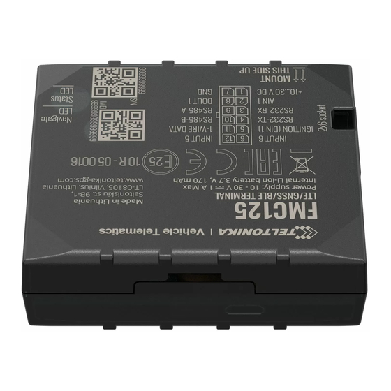
Page 3: Know Your Device
Know your device Figure 1 FMC125 device view FMC125 | Wiki... -
Page 4: Pinout
Pinout Table 1 FMC125 2x6 socket pinout Pin number Pin name Description VCC (10-30)V DC (+) Power supply (+10-30 V DC). Analog input, channel 1. Input range: 0- AIN 1 30 V DC. RS232 – RX Input for data receive through RS232 Output for data transmit through RS232 –... -
Page 5: Wiring Scheme
Wiring scheme Figure 3 FMC125 Wiring scheme Automotive relay FMC125 | Wiki... -
Page 6: Set Up Your Device
Set up your device How to insert SIM card and connect the battery 1. Gently remove FMC125 cover using plastic pry tool from both sides. 2. Insert SIM card as shown with PIN request disabled or read Wiki how to enter it later in Teltonika Configurator. -
Page 7: Pc Connection (Windows)
Setup will continue installing the driver and eventually the confirmation window will appear. Click Finish to complete the setup. 1. Power-up FMC125 with DC voltage (10 – 30 V) power supply using supplied power cable. LED’s should start blinking, see Configuration (Windows) “LED indications”. - Page 8 Most important configurator section is GPRS – where all your server and GPRS settings can be configured and Data Acquisition – where data acquiring parameters can be configured. More details about FMC125 configuration using Configurator can be found in our Wiki. Figure 10 Configurator Status window FMC125 | Wiki...
-
Page 9: Quick Sms Configuration
• server every 120 seconds 2005 – Port • After successful SMS configuration, FMC125 device will • 2006 – Data sending protocol synchronize time and update records to configured server. (0 – TCP, 1 – UDP) Time intervals and default I/O elements can be changed by using Teltonika Configurator parameters. -
Page 10: Mounting Recommendations
Depending on the car model, this may happen in 5 to 30 minutes period. ▬ When the module is connected, measure the voltage again to make sure it did not decrease. ▬ It is recommended to connect to the main power cable in the fuse box. FMC125 | Wiki... -
Page 11: Led Indications
Basic characteristics Table 3 Navigation LED indications Table 5 Basic characteristics Behaviour Meaning Module Name Quectel EC21-AU, Quectel EC21-EC, Teltonika TM2500 Permanently switched on GNSS signal is not received LTE(CaT1)/3G(UMTS/HSPA)/2G(GSM/GPRS)/GNSS/BLU Blinking every second Normal mode, GNSS is working Technology ETOOTH... - Page 12 2 status LED lights Voltage, Engine RPM (CAN Adapters, OBDII dongle) Dual SIM Log Mode, NMEA, LLS, LCD, RFIH HID/MF7, Garmin RS232 Memory 128MB internal flash memory FMI, TCP SCII/Binary RS485 Log Mode, NMEA, LLS, TCP SCII/Binary FMC125 | Wiki...
-
Page 13: Electrical Characteristics
Input voltage (Recommended Operating Conditions) Input Voltage threshold (DIN1) Analog Input Input voltage (Recommended Operating Conditions), Range 1 Input resistance, Range 1 kΩ Measurement error on 12V, Range 1 Additional error on 12 V, Range 1 FMC125 | Wiki... -
Page 14: Safety Information
EN 60950-1 standard. according to the instructions. The device FMC125 is not designed as a navigational device for boats. Battery should not be disposed of with general Do not disassemble the device. If the device is household waste. -
Page 15: Certification And Approvals
• • FMC125 E-Mark FMC125 RoHS • FMC125 Declaration of device operation temperature • This sign on the package means that it is necessary to read the User‘s Manual before your start using the device. Full User‘s Manual version can be found in our Wiki. -
Page 16: Warranty
More information can be found at teltonika.lt/warranty-repair • Repaired • Replaced with a new product • Replaced with an equivalent repaired product fulfilling the same functionality • TELTONIKA can also repair products that are out of warranty at an agreed cost. FMC125 | Wiki...
Need help?
Do you have a question about the FMC125 and is the answer not in the manual?
Questions and answers