Table of Contents
Advertisement
Quick Links
Advertisement
Table of Contents

Related Manuals for Oracle Acme Packet 4500


Summary of Contents for Oracle Acme Packet 4500
- Page 1 Acme Packet 4500 Hardware Installation Guide Formerly Net-Net 4500 October 2013...
- Page 2 Oracle Corporation and its affiliates disclaim any liability for any damages caused by use of this software or hardware in dangerous applications. Oracle and Java are registered trademarks of Oracle and/or its affiliates. Other names may be trademarks of their respective owners.
-
Page 3: Table Of Contents
Fan Module Installation ............49 Version 1.0 Acme Packet 4500 Hardware Installation Guide iii... - Page 4 Powering On the Acme Packet 4500 ........
- Page 5 Acronyms, Definitions, and Terms ..........111 Version 1.0 Acme Packet 4500 Hardware Installation Guide v...
- Page 6 Acme Packet 4500 Hardware Installation Guide Version 1.0...
-
Page 7: About This Guide
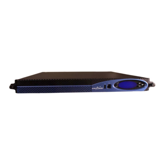
About This Guide Overview The Acme Packet 4500 is a high performance, high capacity session border controller that optimally delivers interactive communications—voice, video, and multimedia sessions—across wireline, wireless, and cable IP network borders. With its compact single unit 1U design the Acme Packet 4500 provides exceptional functionality in a tightly integrated system. - Page 8 • Added Korea to the specifications May 9, 2013 Revision 1.57 • Updated Optical Specification sevtion June 18, 2013 Revision 1.58 • Adds direction about running the halt command before system shut down in Maintenance chapter. viii Acme Packet 4500 Hardware Installation Guide Version 1.0...
-
Page 9: Component Overview
The rear view of the Acme Packet 4500 chassis looks like this: Mounting The Acme Packet 4500 is supported by a pair of cabinet slides that are affixed to an Hardware equipment rack by front and rear mounting flanges. The cabinet slides are adjustable for equipment racks of various depths. - Page 10 These slides are reversible and can be used on either side of the equipment rack. The following image shows a stationary slide, with its front rack rail mounting point on the left. 12 Acme Packet 4500 Hardware Installation Guide Version 1.0...
-
Page 11: System Processor
The following image shows a stationary slide with the rear rack rail mounting point on the left. For installations where the Acme Packet 4500 is installed in 4-post cabinet style • racks with distances ranging from 28” to 32” between the rail flanges, the... - Page 12 Pressing the reset button causes a hard reset, immediately rebooting the Acme Packet 4500. After the reset button is released, the Acme Packet 4500 begins its boot sequence and loads the configured software file.
- Page 13 The USB port is reserved for software-enabled applications. Intake Fans Four intake fans keep the Acme Packet 4500 cool by blowing air through the system chassis. They are a part of the hot-pluggable fan module and are covered by a filter that prevents excess dust and contaminants from entering the system.
-
Page 14: Network Interface Unit
Network Interface Unit The Acme Packet 4500’s network interface unit (NIU) is located on the right side of the chassis’s rear. The single, hot-pluggable NIU contains all media and management interfaces. Media interfaces are located on the right side of the card, while management interfaces are located on the left side of the card. - Page 15 Console Port The console port on the NIU provides console access to the Acme Packet 4500 over a RS-232C serial connection. The Acme Packet 4500 supports only one active serial console connection at a time. The rear console port is useful for customers who want permanent console access;...
- Page 16 The alarm port on the NIU is a flexible interface that closes a circuit when a specific alarm level becomes active on the Acme Packet 4500. The Acme Packet 4500 features an alarm control signal interface that can be used in a CO location to indicate when internal alarms are generated.
- Page 17 NIU. These ports are used for EMS control, RADIUS accounting, CLI management, SNMP queries and traps, and other management functions. Refer to the following image of the Acme Packet 4500’s NIU to see the location of these Ethernet ports. Ethernet Ports...
-
Page 18: Power Components
SFPs, based on compliance testing. Power Components Acme Packet offers AC or DC power options for the Acme Packet 4500. The power supplies are user-replaceable, hot swappable components. 20 Acme Packet 4500 Hardware Installation Guide... - Page 19 Acme Packet 4500 can rely on only one functional power supply to sustain normal operation. A malfunctioning power supply must be removed and replaced as soon as possible. If the Acme Packet 4500 starts up with only one power supply, it will not generate an alarm.
- Page 20 Acme Packet customer support representative. Grounding Terminals The grounding terminals are used to attach the Acme Packet 4500 chassis to a local earth ground. The terminals are located between the two power supplies on the chassis rear.
-
Page 21: Cooling Components
• Fan Module The Acme Packet 4500 chassis pulls cool ambient air into its chassis through intake fans and is exhausted through perforated air outlets located along the rear of the chassis. To avoid overheating the system, do not block the air intake or exhaust ways or otherwise obstruct airflow to the system in any way. - Page 22 When DoS attacks are detected, these attacks are policed and isolated in hardware. The following architectural diagram is a logical representation of the Acme Packet 4500. The Acme Packet 4500’s Network Processor is physically one device. 24 Acme Packet 4500 Hardware Installation Guide...
-
Page 23: Graphic Display
Graphic Display Graphic Display The 4-line graphic display on the Acme Packet 4500’s front control panel is visible at all times. The buttons used to navigate the display are accessible as well. The graphic display reports real-time status, alarms, and general system information. You can view this information without using a console, telnet, or SSH connection into the Acme Packet 4500. -
Page 24: Graphic Display Menus
NET - NET SESSION DIRECTOR The base display of a Acme Packet 4500 in an HA node includes additional information applicable to its HA state. See the "Graphic Display Output for HA Nodes" section in this chapter. - Page 25 Interface slot and port: interface status • Input packets, output packets • Input error packets, output error packets • Slot 1: Port0 UP PKT IN: 1,001K OUT: 223K ERR IN: 0 OUT: 0 Version 1.0 Acme Packet 4500 Hardware Installation Guide 27...
- Page 26 ACLI configuration. The BOOT PARAMS selection displays the IP information necessary to connect to the first Ethernet interface, eth0, located on the rear of the Acme Packet 4500. This interface is used primarily for maintenance, configuration, and downloading software images.
- Page 27 Press the Enter button to return to the Top Menu. ACTIVITY The ACTIVITY display allows you to scroll through current Acme Packet 4500 traffic statistics. These statistics provide a real-time snapshot of the capacity at which the system is operating.
-
Page 28: Graphic Display Output For Ha Nodes
The information included in this section only applies to high availability Acme Packet 4500 nodes. The graphic display on a Acme Packet 4500 in an HA node indicates the current HA state. Five state indications can be displayed on the graphic display. - Page 29 NET - NET SESSION DIRECTOR (S) Acme Packet 4500s in the active state use the default graphic display. The following Active State Displays example shows the display of an active Acme Packet 4500. NET - NET SESSION DIRECTOR Version 1.0...
- Page 30 GRAPHIC DISPLAY 32 Acme Packet 4500 Hardware Installation Guide Version 1.0...
-
Page 31: System Installation
Shipped Parts Each Acme Packet 4500 ships in one box. Inside this box is the Acme Packet 4500 chassis and the accessory kit. The ordered NIU and power supplies are already installed in the chassis. -
Page 32: Preinstallation
The Acme Packet 4500 shall only be installed in a restricted access location. The Acme Packet 4500 must have access to reliable power and cooling. When choosing a location for your Acme Packet 4500 follow the guidelines listed in this section. Environmental... -
Page 33: Mounting Installation
Mounting Installation Overview This section explains how to unpack and install your Acme Packet 4500 in a telecommunications or server equipment rack. The Acme Packet 4500’s standard mounting hardware is used for installation in a 19” 4-post, cabinet-style equipment rack. - Page 34 SYSTEM INSTALLATION Locate the packing list that comes with the Acme Packet 4500 shipment, located outside of shipment box #1. Confirm that all of the components listed in the shipping box contents tables are present and in good condition. If you discover that any of the parts are missing or were damaged in shipment, send an email to tac@acmepacket.com to request assistance.
- Page 35 SYSTEM INSTALLATION Chassis Slide only (2 x shipped) Slide Extender Kit (2 x shipped) Nut Bar (4 x shipped) Mounting Spacer (2 x shipped) Version 1.0 Acme Packet 4500 Hardware Installation Guide 37...
-
Page 36: Cabinet-Style 4-Post Chassis Installation
Flat Head Screw 10-32 x 5/16" (6 x shipped) Center mounting ears (2 x shipped) Cabinet-style 4-Post Chassis Installation The following sections explain how to mount your Acme Packet 4500 in a cabinet- style, 4-post equipment rack. Mounting System Acme Packet provides flexible mounting options for your Acme Packet 4500 equipment rack installation. - Page 37 28” and 32” (71.1 cm and 81.3 cm), the slide extenders are required for mounting the system. Attach these slide extenders to the stationary slides as a preliminary step in Acme Packet 4500 installation.
- Page 38 Screw in and secure the stationary rail to the equipment rack. Refer to the following exploded view of procedure: Do not completely torque the screws; leave a small amount of play at this point. 40 Acme Packet 4500 Hardware Installation Guide Version 1.0...
- Page 39 Expand and line up the unpainted side of the stationary rail on the outside of the rear rack rail at the same height used for the front mount point. Place one 10-32 screw through the stationary rail ear and screw in place. Version 1.0 Acme Packet 4500 Hardware Installation Guide 41...
- Page 40 To install the stationary rails on the front of a square hole equipment rack: Locate the following components: 2 x stationary rail sections • 4 x 10-32 x 5/8” screws • 2 x mounting spacers • 42 Acme Packet 4500 Hardware Installation Guide Version 1.0...
- Page 41 Note: The images used in this procedure refer to the stationary slide without slide extenders installed. The procedure is essentially the same with the slide extender’s flange placed on the outside of the rear rack rail. Locate the following components: Version 1.0 Acme Packet 4500 Hardware Installation Guide 43...
- Page 42 In this second portion of system installation, two chassis ears and two chassis slides Chassis Ears and are secured to the Acme Packet 4500 chassis. Slides To install the chassis rails on the Acme Packet 4500 chassis: Locate the following components: • 4 x 10-32 x 5/16" flat head (black) screws 2 x front mounting ears •...
- Page 43 Use 3 x 6-32 x 5/16” screws to secure the chassis slide to the chassis. Notice that the large hole in the slide is positioned toward the front of the Acme Packet 4500 chassis. large hole Repeat this procedure for the other side of the Acme Packet 4500 chassis.
- Page 44 To install the Acme Packet 4500 chassis in the equipment rack: Lift the Acme Packet 4500 into the correct position in the equipment rack. Insert the chassis slides into the stationary slides. Push the Net-Net 4500 fully into the equipment rack.
-
Page 45: Center-Mount 2-Post Chassis Installation
SYSTEM INSTALLATION Center-mount 2-Post Chassis Installation The following sections explain how to mount your Acme Packet 4500 in a center- mount, 2-post equipment rack. The Acme Packet 4500 in a center mount installation looks like this: Installing the Center mounting ears are attached to each side of the Acme Packet 4500. These Center-mount mounting ears are reversible, and are not mated to a specific side of the chassis. - Page 46 Repeat this procedure for the other side of the Acme Packet 4500 chassis. Installing the Chassis You now will lift the Acme Packet 4500 and install it into the rack. To prevent in the Rack personal injury or damage to the Acme Packet 4500, follow these guidelines: This installation requires two people and should not be attempted otherwise.
-
Page 47: Fan Module Installation
SYSTEM INSTALLATION Fan Module Installation The fan module is preinstalled in the Acme Packet 4500 chassis when it ships. There is no need to remove the fan module prior to installation. In case this part needs service or replacement, you can remove and replace it with a functioning one. - Page 48 SYSTEM INSTALLATION To install the grounding cable on the Acme Packet 4500: Unscrew and remove the two kep nuts from the grounding posts located on the rear of the Acme Packet 4500. Place them aside. Place the lug on the end of the grounding cable onto the grounding posts in the orientation shown in the following image.
- Page 49 Use a 5 Amp fused circuit for each AC power supply. To install the AC power cords in the Acme Packet 4500: Locate the two AC power cords shipped with your Acme Packet 4500. Choose one power supply to work on first.
- Page 50 You can cable the DC power supply out-of-chassis, and then insert the power supply and cable assembly into the Acme Packet 4500 chassis in one step. This method is easier than cabling the DC power supplies once they have been inserted into the chassis.
- Page 51 Repeat Steps 2 and 3, with the white lead inserted into the middle terminal and the black lead inserted into the lower terminal. Version 1.0 Acme Packet 4500 Hardware Installation Guide 53...
-
Page 52: Cabling The Acme Packet 4500
NIU. The Acme Packet 4500 ships with a console adapter, which allows you to connect a standard DB-9 serial port to the Acme Packet 4500’s RJ45 console port. Only one console port on the Acme Packet 4500 can be used at a time. - Page 53 This is meant to direct the installer to use the front panel console port for initial configuration. NIU Console Cabling This section explains how to create a serial connection to the Acme Packet 4500’s Procedure NIU console port. Use the rear panel console port primarily for permanent connections to a terminal server or other serial device.
- Page 54 The following figure shows a Acme Packet 4500 with a console cable properly connected (in addition to the Alarm cable). Front Panel Console This section explains how to create a serial connection to the Acme Packet 4500’s Cabling Procedure front panel console port.
- Page 55 You can use the alarm port to indicate electrically when an alarm has been generated on the Acme Packet 4500. The alarm port contains leads for three circuits, each of which closes to signify a corresponding alarm. Refer to this guide’s...
- Page 56 Mgmt2. The release tab on the RJ45 jack will click into place when you insert it properly. Route the cable away from the Acme Packet 4500 chassis. Make sure that the Ethernet cables are not stretched tightly or subject to extreme stress.
- Page 57 To connect Ethernet cables to the GigE Copper ports on the NIU: Locate the Ethernet cables you plan to connect to the Acme Packet 4500. Insert the RJ45 connector on the end of the Ethernet cable into one of the GigE copper NIU media and signaling ports.
- Page 58 To connect network GigE optical cabling to the GigE optical physical interface cards: Locate the GigE fiber optic cables you plan to connect to the Acme Packet 4500. Insert the duplex LC connector on the end of the fiber cable into one of the NIU’s SFP optical transceivers.
-
Page 59: Cabling For Ha Deployments
These media and signaling ports from left to right are labeled: S0P0, S0P1, S1P0, S1P1. Route the cable away from the Acme Packet 4500. Make sure that the fiber optic cables are not stretched tightly or subjected to extreme stress. - Page 60 Insert one end of a second Ethernet cable into mgmt2 on the rear panel of Net- Net SBC1. The release tab on the RJ45 jack clicks into place when you insert it properly. 62 Acme Packet 4500 Hardware Installation Guide Version 1.0...
- Page 61 Acme Packet 4500s in an HA node, the standby system sends out an ARP message using a configured virtual MAC address, establishing that MAC on another physical port on the same Ethernet switch. Version 1.0 Acme Packet 4500 Hardware Installation Guide 63...
- Page 62 SYSTEM INSTALLATION 64 Acme Packet 4500 Hardware Installation Guide Version 1.0...
-
Page 63: Startup
PC or terminal server to the Acme Packet 4500’s console port. You must connect to the front console port on initial boot. If the Acme Packet 4500 is already powered on, press the Enter key a few times to activate the console connection. When ACLI text is displayed on the screen, the console connection has been successfully created. -
Page 64: Powering On The Acme Packet 4500
Acme Packet 4500 to either AC or DC power. Flip the power supply switches on the rear panel of the Acme Packet 4500 to the ON position by pressing the 1 side of the switch. - Page 65 Superuser mode. Password: ACMEPACKET# You can now begin configuring your Acme Packet 4500. Refer to the Net-Net Configuration Guide to learn how to establish an IP address for your Acme Packet 4500. Version 1.0...
- Page 66 STARTUP 68 Acme Packet 4500 Hardware Installation Guide Version 1.0...
-
Page 67: Maintenance
Procedures to reroute call and network traffic around the Acme Packet 4500 are outside the scope of this guide. You can set the Acme Packet 4500 to reject all incoming calls from your system with the set-system-state command. When set to offline, this command lets calls in progress continue uninterrupted, but no new calls are admitted. -
Page 68: Rebooting, Resetting, And Power Cycling
To shut down the Acme Packet 4500 hardware: Exit the ACLI and close your console or network connection. Turn off the power supply switches on the rear panel of the Acme Packet 4500 by pressing the 0 side of the switch. - Page 69 Reboot this SD [y/n]?: y System Reset Resetting the Acme Packet 4500 via the front of the chassis performs a cold reboot. This is the equivalent to disconnecting the power from the system and then reconnecting it. There is no orderly termination of tasks, and the system shuts down abruptly.
-
Page 70: Standby Mode For Ha Nodes
4500s are configured as an HA node, you should only work on the Acme Packet 4500 that is in standby mode. There are two ways to determine the HA state of each Acme Packet 4500 in an HA pair. If you are in the same physical location as the Acme Packet 4500s, you can view the graphic display on the front panel. - Page 71 MAINTENANCE To force a Acme Packet 4500 into the standby HA state: Confirm that the relevant systems on Net-Net SBC1 and Net-Net SBC2 are synchronized with the show health command. Type show health and press <Enter> on each system. NETNETSBC1# show health...
- Page 72 HA node using the new NIU. You can confirm system state by using the show health command. Please refer to the “HA Functionality” section in the Fault Management Chapter of the Net-Net 4000 Maintenance and Troubleshooting Guide for more information. 74 Acme Packet 4500 Hardware Installation Guide Version 1.0...
-
Page 73: Chassis Removal
Packet 4500 from below while the other person removes the system chassis from the equipment rack. Pull the Acme Packet 4500 forward and out of the equipment rack. Lift the Acme Packet 4500 out of the equipment rack, and set it on a flat and stable surface. Version 1.0... -
Page 74: Power Supply Removal And Replacement
The vendor is identified by the label on top of the power supply. The power supply is a user-replaceable component. If a Acme Packet 4500 power supply malfunctions, you should remove the malfunctioning power supply and replace it. - Page 75 MAINTENANCE To remove a power supply from the Acme Packet 4500 chassis: Remove the AC or DC power cables (see: Ground and Power Cable Installation) from the power supplies. Turn the locking screw fully counterclockwise to unlock the power supply from the chassis.
- Page 76 MAINTENANCE AC or DC Power You can replace AC and DC power supplies in the Acme Packet 4500 chassis using Supply Replacement the reverse procedure as removing them. You can also install power supplies in the Acme Packet 4500 chassis before or after the chassis is mounted in an equipment rack.
- Page 77 MAINTENANCE Insert the power supply into the power supply bay located on the rear panel of the Acme Packet 4500 chassis in the orientation shown below. The labels on the power supply face upward. Turn the locking screw counterclockwise until it stops. This retracts the locking mechanism and the power supply can be completely inserted into the system chassis.
-
Page 78: Fan Module And Filter Maintenance
When removing and replacing a fan module, remember to first ground yourself using appropriate ESD grounding equipment such as a wrist or heel strap. 80 Acme Packet 4500 Hardware Installation Guide Version 1.0... - Page 79 Replacing the Fan To obtain a replacement fan module, contact your Acme Packet customer support Module representative directly or email support@acmepacket.com. Replacing the fan module is the reverse process as removing it. Version 1.0 Acme Packet 4500 Hardware Installation Guide 81...
- Page 80 Holding the pull tab on the fan module, insert the fan module squarely into the chassis.Continue to push the fan module into the Acme Packet 4500 until its panel lies flush with the Acme Packet 4500’s rear panel. You will feel the module’s connector secure itself to the motherboard.
- Page 81 Cooling maintenance encompasses cleaning the fan module and cleaning the air inlets on the front of the Acme Packet 4500’s chassis. Cleaning the fan module requires that you remove the module itself. If you are not shutting down the Acme Packet 4500, this procedure must be performed quickly or else the system may overheat and cause packet processing to stop.
-
Page 82: Niu Removal And Replacement
NIU Removal and Replacement When possible, remove system power before removing and replacing an NIU. However, without powering down the Acme Packet 4500, you can exchange an NIU (for the same type of card) by removing and replacing it. Upon NIU removal, the Acme Packet 4500 enters an Out-of-Service state. - Page 83 Pivot the two ejection levers outward at the same time, pulling the card out of its connection to the motherboard and away from the system chassis. This action disengages the NIU from the system, severing all electrical contact to the processing unit. Version 1.0 Acme Packet 4500 Hardware Installation Guide 85...
- Page 84 MAINTENANCE Pull the loosened NIU out of the Acme Packet 4500 chassis by holding each side of the NIU’s front panel. Place the NIU in an antistatic bag while it remains outside of the Acme Packet 4500 chassis. To install an NIU in the Acme Packet 4500 chassis: NIU Replacement Locate the NIU.
- Page 85 The guide rails guide the interface unit to engage the NIU bus connector squarely. Slide the card into the Acme Packet 4500 chassis. The physical interface card circuit board slides into the guide rails in the NIU bay of the system chassis.
- Page 86 Screw the NIU into the chassis with a #2 Phillips screwdriver. This creates the final connection between the interface unit and the chassis. Replace all network and management cabling. 88 Acme Packet 4500 Hardware Installation Guide Version 1.0...
-
Page 87: Optical Transceiver Removal And Replacement
Serves as the receptacle for the LC duplex fiber optic connectors. Optical transceivers are hot swappable and may be replaced while the Acme Packet 4500 is powered on. Leave the NIU in the Acme Packet 4500 as you extract the optical transceiver. - Page 88 SX 850 nm 550 m single-mode label is on the back. It multi-mode label is on the back.It uses uses a yellow colored fiber optic cable. an orange colored fiber optic cable. 90 Acme Packet 4500 Hardware Installation Guide Version 1.0...
-
Page 89: Media Cables
Three different fiber optic cables used on the Net-Net 4500 media cards. Multi-mode transceivers take an orange fiber optic cable. • Single-mode transceivers take a yellow fiber optic cable. • Copper transceiver take cat 5 or 6 ethernet cable. • Version 1.0 Acme Packet 4500 Hardware Installation Guide 91... - Page 90 MAINTENANCE Cable SX Multi mode orange colored fiber optic cable 62.5/125 Identification LX Single mode yellow colored fiber optic cable 9/125 92 Acme Packet 4500 Hardware Installation Guide Version 1.0...
- Page 91 Removing an Optical To remove the optical transceiver on an NIU’s SFP port: Transceiver Unplug all GigE fiber optic cables from the optical transceiver to be replaced. bale clasps in rest position Version 1.0 Acme Packet 4500 Hardware Installation Guide 93...
-
Page 92: Alarms
Slide the replacement optical transceiver into the SFP socket on the NIU. Flip the bale clasp latch back into the rest position. Reconnect the optical cables to their corresponding ports. GigE Copper transceivers are also available for the Acme Packet 4500. They are GigE Copper Transceivers removed and replaced similarly to the optical transceivers. - Page 93 (where XX.XX is the temperature in MINOR: >95°C is abnormally hot. temperature in degrees) degrees) If this alarm occurs, the Acme Packet 4500 turns the fan speed up to the fastest possible speed. Version 1.0 Acme Packet 4500 Hardware Installation Guide 95...
- Page 94 MINOR: speed of one fan> 75% and <90%, the other two fans are at normal speed If this alarm occurs, the Acme Packet 4500 turns the fan speed up to the fastest possible speed. Environmental Sensor The following table lists the environmental sensor alarm.
- Page 95 NIU. PHY0 encompasses S0P0 and S0P1, while PHY1 encompasses S1P0 and S1P1. Therefore, both insertion and both removal alarms will be activated at the same time when the NIU is inserted or removed from the Acme Packet 4500. Graphic Display...
- Page 96 VXINTF LINK DOWN ALARM 131081 MAJOR Mgmt1 link down Port 1 DOWN X LINK ALARMS VXINTF LINK DOWN ALARM 131082 MAJOR Mgmt2 link down Port 2 DOWN X LINK ALARMS VXINTF 98 Acme Packet 4500 Hardware Installation Guide Version 1.0...
- Page 97 65567 CRITICAL S1P1 SFP Inserted Slot 1 Port 1 SFP GIGPORT 3 Inserted When an SFP module is inserted or removed from an NIU, there is no impact on system health. Version 1.0 Acme Packet 4500 Hardware Installation Guide 99...
- Page 98 MAINTENANCE 100 Acme Packet 4500 Hardware Installation Guide Version 1.0...
-
Page 99: Safety
Acme Packet 4500 from experiencing any harm during the installation process. These chapters also provide information that helps to keep your Acme Packet 4500 functioning properly and keep it from damage. General Safety Precautions To ensure general safety, follow the safety precautions listed in this section. -
Page 100: Battery Warning
SAFETY Precautions Note the locations of the power supply switches on the Acme Packet 4500, and • the location of the emergency power-off switch for the room where the Acme Packet 4500 is located. If an electrical accident occurs, remove power from the system immediately by •... -
Page 101: Environmental, Safety, And Regulatory Certifications
If your equipment rack is painted, you should ground the system to some other reliable place or remove a small portion of paint for proper grounding. Use a grounded ESD wrist strap when working on the Acme Packet 4500 to • prevent static discharge. - Page 102 SAFETY 104 Acme Packet 4500 Hardware Installation Guide Version 1.0...
-
Page 103: Specifications
Specifications Introduction This chapter provides information regarding the physical, electrical, environmental, and connector specifications of the Acme Packet 4500. It also lists regulatory specifications and certifications. Physical Specifications Acme Packet 4500 This table lists the Net-Net 4500’s physical dimensions and weight. -
Page 104: Electrical Specifications
Max AC switching current 0.3 A @ 125 VAC Max DC switching current 1 A @ 30 VDC Environmental Specifications For the Acme Packet 4500 to function properly, we recommend that you follow the environmental guidelines in the following table. Specification Description Temperature... -
Page 105: Connector Specifications
The terminal block connections accept a bare (tinned) wire for DC power installations. Optical Transceiver Interface Module Specification Refer to the following table for information about the optical specifications of the GigE SFP optical transceivers for the Acme Packet 4500. Specification Multimode (SX) Fiber Module Singlemode (LX) Fiber Module Wavelength λ... -
Page 106: Regulatory Specifications And Certifications
Korea CE Mark indicated by * above The Acme Packet 4500 has been tested and found to comply with the limits for a Class A digital device, pursuant to Part 15 of the FCC Rules. These limits are designed to provide reasonable protection against harmful interference when the equipment is operated in a commercial environment. -
Page 107: Weee Directive Compliance
At the time of collection, Acme Packet covers the cost of shipping equipment back to its headquarters. For information about how to dispose of your Acme Packet equipment, visit our Web site at http://www.acmepacket.com/recycle. Version 1.0 Acme Packet 4500 Hardware Installation Guide 109... - Page 108 SPECIFICATIONS 110 Acme Packet 4500 Hardware Installation Guide Version 1.0...
-
Page 109: Glossary
The IEEE is best known for developing standards for the computer and electronics industry. ICES—Interference-causing Equipment Standard IEC—International Electrotechnical Commission IETF—Internet Engineering Task Force is the main standards organization for the Internet. Version 1.0 Acme Packet 4500 Hardware Installation Guide 111... - Page 110 NVRAM—Non-volatile Random Access Memory is a type of memory that retains its contents when power is turned off. Optical Transceiver—The fiber connection to the Acme Packet 4500 plugs into an optical transceiver. Through this connection, light energy is converted into electrical energy.
- Page 111 VFD—Vacuum Fluorescent Display is used on the graphic display window of the Acme Packet 4500 chassis’s front control panel. VLAN—Virtual Local Area Network refers to a network of computers are connected to a single physical segment of a wire but behave as if they are connected to the physically diverse LANs.
- Page 112 GLOSSARY 114 Acme Packet 4500 Hardware Installation Guide Version 1.0...
Need help?
Do you have a question about the Acme Packet 4500 and is the answer not in the manual?
Questions and answers