
Related Manuals for Oracle Acme Packet 4500


Summary of Contents for Oracle Acme Packet 4500
- Page 1 Acme Packet 4500 Hardware Installation and Maintenance Guide Formerly Net-Net 4500 April 2015...
- Page 2 Oracle Corporation and its affiliates disclaim any liability for any damages caused by use of this software or hardware in dangerous applications. Oracle and Java are registered trademarks of Oracle and/or its affiliates. Other names may be trademarks of their respective owners.
-
Page 3: Table Of Contents
Graphic Display Output for HA Nodes ..........31 Acme Packet 4500 Hardware Installation and Maintenance Guide... - Page 4 Powering On the Acme Packet 4500 ........
- Page 5 I ............Index105 Acme Packet 4500 Hardware Installation and Maintenance Guide...
- Page 6 Acme Packet 4500 Hardware Installation and Maintenance Guide...
-
Page 7: About This Guide
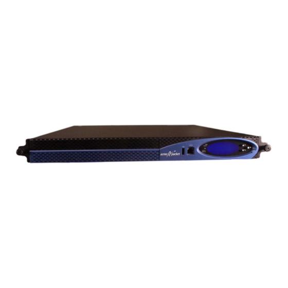
About This Guide Overview The Acme Packet 4500 is a high performance, high capacity session border controller that optimally delivers interactive communications — voice, video, and multimedia sessions — across wireline, wireless, and cable IP network borders. With its compact single unit 1U design the Acme Packet 4500 provides exceptional functionality in a tightly integrated system. - Page 8 • Adds direction about running the halt command before system shut down in Maintenance chapter. November 11, 2013 Revision 1.59 • Removed all instances of Net-Net March 17, 2014 Revision 1.60 • Edit and standardize formatting of content Acme Packet 4500 Hardware Installation and Maintenance Guide...
- Page 9 Safety and Compliance Guide for details on the topic. April 20, 2015 Revision 1.62 • Inserted caveats to confirm that Acme Packet 4500 hardware installation documentation satisfies NEBS (Network Equipment-Building System) requirements. Version 1.0 Acme Packet 4500 Hardware Installation and Maintenance Guide 3...
- Page 10 ABOUT THIS GUIDE Acme Packet 4500 Hardware Installation and Maintenance Guide...
-
Page 11: Safety
Acme Packet 4500 from experiencing any harm during the installation process. These chapters also provide information that helps to keep your Acme Packet 4500 functioning properly and keep it from damage. Safety and Regulatory Certifications... -
Page 12: Electrical Safety Precautions
SAFETY Electrical Safety Precautions To protect yourself from harm and the Acme Packet 4500 from damage, follow these electrical safety precautions: Precautions • Note the locations of the power supply switches on the Acme Packet 4500, and the location of the emergency power-off switch for the room where the Acme Packet 4500 is located. -
Page 13: Esd Safety
• Use a grounded ESD wrist strap when working on the Acme Packet 4500 to prevent static discharge. To avoid damaging ESD-sensitive hardware, discharge all static electricity from •... - Page 14 SAFETY Acme Packet 4500 Hardware Installation and Maintenance Guide...
-
Page 15: Component Overview
Figure 2 - 2. Acme Packet 4500 Rear Panel Mounting The Acme Packet 4500 is supported by a pair of cabinet slides that are affixed to an Hardware without equipment rack by front and rear mounting flanges. The cabinet slides are adjustable Locking for equipment racks of various depths. - Page 16 The chassis section slides are shipped inserted into the stationary section slides as shown in the following image: Figure 2 - 3. Assembled Acme Packet 4500 Slide Rail You screw the chassis section slides in place on both sides of the Acme Packet •...
- Page 17 Figure 2 - 7. Slide Extender Mounting The Acme Packet 4500 is supported by a pair of cabinet slides that are affixed to an Hardware with equipment rack by front and rear mounting flanges. The cabinet slides are adjustable Locking for equipment racks of various depths.
- Page 18 Figure 2 - 8. Assembled Chassis Slides The slide rails that are bolted to either side of the chassis or equipment rack are • reversible and can be used on either side of the Acme Packet 4500. Figure 2 - 9. Locking Clip •...
-
Page 19: System Processor
The Acme Packet 4500 processor module (CPU) is located on the main board of the (CPU) Acme Packet 4500. The CPU is a (FRU) and is attached to the main board as a daughter card. This processor module handles both the management and signal processing within the system. -
Page 20: System Control Panels
Pressing the reset button causes a hard reset, immediately rebooting the Acme Packet 4500. After the reset button is released, the Acme Packet 4500 begins its boot sequence and loads the configured software file. - Page 21 Alarm Active LED The alarm LED on the front control panel indicates if any alarms are active on the Acme Packet 4500. The LED can be three different colors to indicate the severity of the alarms. Unlit—system is fully functional without any faults •...
-
Page 22: Network Interface Unit
Network Interface Unit The Acme Packet 4500’s network interface unit (NIU) is located on the right side of the chassis’s rear. The single, hot-pluggable NIU contains all media and management interfaces. Media interfaces are located on the right side of the card, while management interfaces are located on the left side of the card. - Page 23 Console Port The console port on the NIU provides console access to the Acme Packet 4500 over a RS-232C serial connection. The Acme Packet 4500 supports only one active serial console connection at a time. The rear console port is useful for customers who want permanent console access;...
- Page 24 The alarm port on the NIU is a flexible interface that closes a circuit when a specific alarm level becomes active on the Acme Packet 4500. The Acme Packet 4500 features an alarm control signal interface that can be used in a CO location to indicate when internal alarms are generated.
- Page 25 NIU. These ports are used for EMS control, RADIUS accounting, CLI management, SNMP queries and traps, and other management functions. Refer to the following image of the Acme Packet 4500’s NIU to see the location of these Ethernet ports. Figure 2 - 22. Ethernet Ports...
-
Page 26: Power Components
SFPs, based on compliance testing. Power Components The Acme Packet 4500 offers AC or DC power options for the Acme Packet 4500. The power supplies are user-replaceable, hot swappable components. Acme Packet 4500 Hardware Installation and Maintenance Guide... - Page 27 Acme Packet 4500 can rely on only one functional power supply to sustain normal operation. A malfunctioning power supply must be removed and replaced as soon as possible. If the Acme Packet 4500 starts up with only one power supply, it will not generate an alarm.
- Page 28 Power switches are located on the system’s power supplies and face rearward from Switch the Acme Packet 4500. The Acme Packet 4500 has no other power switches. For normal operation, the switches on each power supply should be in the ON position.
-
Page 29: Cooling Components
COMPONENT OVERVIEW Grounding Terminals The grounding terminals are used to attach the Acme Packet 4500 chassis to a local earth ground. The terminals are located between the two power supplies on the chassis rear. Cooling Components The Acme Packet 4500 must remain well ventilated for reliable and continuous operation. -
Page 30: Acme Packet4000 Series Hardware Architecture
When DoS attacks are detected, these attacks are policed and isolated in hardware. The following architectural diagram is a logical representation of the Acme Packet 4500. The Acme Packet 4500’s Network Processor is physically one device. Figure 2 - 28. Acme Packet 4500 Hardware Architecture... -
Page 31: Graphic Display
Graphic Display Graphic Display The four-line graphic display on the Acme Packet 4500 front control panel is visible at all times. The buttons used to navigate the display are accessible as well. The graphic display reports real-time status, alarms, and general system information. -
Page 32: Display Modes
NET - NET SESSION DIRECTOR The base display of an Acme Packet 4500 in an HA node includes additional information applicable to its HA state. See the Graphic Display Output for HA Nodes section in this chapter. - Page 33 Figure 3 - 31. Available Global Menu Options INTERFACE The INTERFACE menu allows you to scroll through a list of all configured physical interfaces. The management and media physical interfaces appear in the list, as does the loopback interface. Acme Packet 4500 Hardware Installation and Maintenance Guide...
- Page 34 ACLI configuration. The BOOT PARAMS selection displays the IP information necessary to connect to the first Ethernet interface, eth0, located on the rear of the Acme Packet 4500. This interface is used primarily for maintenance, configuration, and downloading software images.
- Page 35 Press the Enter button to return to the Top Menu. ACTIVITY The ACTIVITY display allows you to scroll through current Acme Packet 4500 traffic statistics. These statistics provide a real-time snapshot of the capacity at which the system is operating.
- Page 36 Press the Enter button to return to the Top Menu RETURN Pressing the Enter button for the RETURN selection returns you to the base display during normal operating conditions or to the alarm display during an alarm condition. Acme Packet 4500 Hardware Installation and Maintenance Guide...
-
Page 37: Graphic Display Output For Ha Nodes
The information included in this section only applies to high availability Acme Packet 4500 nodes. The graphic display on a Acme Packet 4500 in an HA node indicates the current HA state. Five state indications can be displayed on the graphic display. - Page 38 GRAPHIC DISPLAY Acme Packet 4500 Hardware Installation and Maintenance Guide...
-
Page 39: System Installation
Shipped Parts Each Acme Packet 4500 ships in one box. Inside this box is the Acme Packet 4500 chassis and the accessory kit. The ordered NIU and power supplies are already installed in the chassis. -
Page 40: Pre-Installation
The Acme Packet 4500 shall only be installed in a restricted access location. The Acme Packet 4500 must have access to reliable power and cooling. When choosing a location for your Acme Packet 4500, follow the guidelines listed in this section. Environmental... -
Page 41: Mounting Installation
Mounting Installation Overview This section explains how to unpack and install your Acme Packet 4500 in a telecommunications or server equipment rack. The Acme Packet 4500 standard mounting hardware is used for installation in a 19” 4-post, cabinet-style equipment rack. - Page 42 Open the exterior box. Unpack the contents of the Acme Packet 4500 shipment. Locate the packing list that comes with the Acme Packet 4500 shipment, located outside of shipment box #1. Confirm that all of the components listed in the shipping box contents tables are present and in good condition.
- Page 43 Figure 4 - 35. Chassis Slide The Slide Extender Kit (2 x shipped) is used to extend the length of the stationary • slide. Figure 4 - 36. Slide Extender Kit Acme Packet 4500 Hardware Installation and Maintenance Guide...
- Page 44 Phillips Screw 10-32 x 5/8” (8 x shipped): Phillips Screw 6-32 x 5/16” (6 x shipped) Flat Head Screw 10-32 x 5/16" (6 x shipped) Figure 4 - 39. Assorted Screws Acme Packet 4500 Hardware Installation and Maintenance Guide...
-
Page 45: Cabinet-Style 4-Post Chassis Installation
Stationary slides are mounted on each side of the equipment rack. Complimentary chassis slides are mounted on each side of the Acme Packet 4500 chassis. Once the equipment rack and chassis hardware is in place, the chassis can be inserted along its slide rails into the equipment rack. - Page 46 Figure 4 - 43. Completed Chassis Slide with Extender Attached Tapped Hole Rack This section explains how to mount the Acme Packet 4500 mounting rail assembly Installation in a tapped hole equipment rack. To install the stationary rails on the front of a tapped hole equipment rack:...
- Page 47 Screw in and secure the stationary rail to the equipment rack. Refer to the following exploded view of the procedure. Figure 4 - 45. Exploded View of Assembly Detail Do not completely torque the screws; leave a small amount of play at this point. Acme Packet 4500 Hardware Installation and Maintenance Guide...
- Page 48 Figure 4 - 47. Rack with Stationary Rails Installed To install the stationary rails on the rear of a tapped hole equipment rack: Locate the following components: 4 x 10-32 x 5/8” screws • Acme Packet 4500 Hardware Installation and Maintenance Guide...
- Page 49 Repeat this procedure for the rear of the other stationary slide. A stationary rail with slide extender installed in an equipment rack is shown below. Figure 4 - 50. Stationary Slide with Slide Extender Attached to Rack Acme Packet 4500 Hardware Installation and Maintenance Guide...
- Page 50 Figure 4 - 51. Stationary Slides and Extenders Installed in Equipment Rack Square Hole Rack This section explains how to mount the Acme Packet 4500 mounting rail assembly Installation in a square hole equipment rack. You can use 10-32 cage nuts as an alternative to the provided nut bars, but they must be mounted prior to this procedure.
- Page 51 The procedure is essentially the same with the slide extender flange placed on the outside of the rear rack rail. Locate the following components: 4 x 10-32 x 5/8” screws • 2 x nut bar • Acme Packet 4500 Hardware Installation and Maintenance Guide...
- Page 52 In this second portion of system installation, two chassis ears and two chassis slides Chassis Ears and are secured to the Acme Packet 4500 chassis. Slides To install the chassis rails on the Acme Packet 4500 chassis: Locate the following components: • 4 x 10-32 x 5/16" flat head (black) screws •...
- Page 53 Repeat this procedure for the other side of the Acme Packet 4500 chassis. Installing the You now lift the Acme Packet 4500 and install it into the rack. To prevent personal Chassis in the injury or damage to the Acme Packet 4500, follow these guidelines: Rack This installation requires two people and should not be attempted otherwise.
-
Page 54: Center-Mount 2-Post Chassis Installation
Fully tighten all 4, 10-32 x 5/8” front screws that hold the stationary rails to the rack. Center-Mount 2-Post Chassis Installation The following sections explain how to mount your Acme Packet 4500 in a center- mount, 2-post equipment rack. The Acme Packet 4500 in a center mount installation is pictured below. - Page 55 Repeat this procedure for the other side of the Acme Packet 4500 chassis. Installing the Chassis Lift the Acme Packet 4500 and install it into the rack according to the following in the Rack procedure. To prevent personal injury or damage to the Acme Packet 4500, follow these guidelines: •...
-
Page 56: Fan Module Installation
Fan Module Installation The fan module is pre-installed in the Acme Packet 4500 chassis when it ships. There is no need to remove the fan module prior to installation. In case this part needs service or replacement, you can remove and replace it with a functioning one. - Page 57 The ground terminals are located between the two power supplies on the rear of the Installation chassis. The Acme Packet 4500 ships with two kep nuts screwed onto the ground terminals. Use an 11/32” nut driver to remove and install these kep nuts.
- Page 58 Electrical Code (NEC) applies. To install the AC power cords in the Acme Packet 4500: Locate the two AC power cords shipped with your Acme Packet 4500. Choose one power supply to work on first. Connect one power cord to the power supply by inserting the 3-lead IEC-320 plug into the IEC connector located on the power supply.
- Page 59 You can cable the DC power supply out-of-chassis, and then insert the power supply and cable assembly into the Acme Packet 4500 chassis in one step. This method is easier than cabling the DC power supplies once they have been inserted into the chassis.
- Page 60 Use a 10 Amp fused circuit for each DC power supply. To install the DC power cable on a DC power supply: Locate the two DC power cables shipped with your Acme Packet 4500. Press the tip of a flat screwdriver into the terminal release slot, and push the screwdriver to the right to open the cage clamp.
- Page 61 Once the DC power supply is inserted into the chassis, route the DC power cord through your rack and cabling system to the -48 VDC power supply. Connect the supply leads of the DC power cord to the DC power supply. Acme Packet 4500 Hardware Installation and Maintenance Guide...
-
Page 62: Cabling The Acme Packet 4500
The console port located on the front panel is the default. This may be changed by configuration. Only one console port on the Acme Packet 4500 can be used at a time. Some text may be output to the non-active console port. This is normal. However, only input from the active console port can be recognized by the Acme Packet 3820. - Page 63 Figure 4 - 76. Dust Cover NIU Console Cabling This section explains how to create a serial connection to the Acme Packet 4500 NIU Procedure console port. Use the rear panel console port primarily for permanent connections to a terminal server or other serial device.
- Page 64 (in addition to the Alarm cable). Figure 4 - 79. Console Cable Connected Front Panel Console This section explains how to create a serial connection to the Acme Packet 4500 front Cabling Procedure panel console port. Refer to the Startup chapter of this guide for information on how to configure your terminal application to connect to the console.
- Page 65 You can use the alarm port to indicate electrically when an alarm has been generated on the Acme Packet 4500. The alarm port contains leads for three circuits, each of which closes to signify a corresponding alarm. Refer to the Component Overview chapter in this document for a description of how to build an alarm cable and interface it with your monitoring system.
- Page 66 Figure 4 - 83. Rear Panel Ethernet Cable Ports Route the cable away from the Acme Packet 4500 chassis. Make sure that the Ethernet cables are not stretched tightly or subject to extreme stress. The following figure shows a Acme Packet 4500 with a network management cable...
- Page 67 S0P0, S0P1, S1P0, S1P1. Figure 4 - 85. Media and Signaling Ports Route the cable away from the Acme Packet 4500. Make sure that the Ethernet cables are not stretched tightly or subjected to extreme stress.
- Page 68 To connect network GbE optical cabling to the GbE optical physical interface cards: Locate the GbE fiber optic cables you plan to connect to the Acme Packet 4500. Insert the duplex LC connector on the end of the fiber cable into one of the NIU SFP optical transceivers.
-
Page 69: Cabling For Ha Deployments
SYSTEM INSTALLATION Route the cable away from the Acme Packet 4500. Make sure that the fiber optic cables are not stretched tightly or subjected to extreme stress. The following figure shows a Acme Packet 4500 with media network cable properly connected and inserted in S0P0. - Page 70 Acme Packet 4500s in an HA node, the standby system sends out an ARP message using a configured virtual MAC address, establishing that MAC on another physical port on the same Ethernet switch. Acme Packet 4500 Hardware Installation and Maintenance Guide...
-
Page 71: Startup
Creating a Console Connection This section explains how to create a console connection. Prerequisites In order to create a console connection to the Acme Packet 4500, you need to configure the terminal hardware/software appropriately. The following table lists your terminal application serial configurations. -
Page 72: Powering On The Acme Packet 4500
STARTUP If the Acme Packet 4500 is already powered on, press the Enter key a few times to activate the console connection. When ACLI text is displayed on the screen, the console connection has been successfully created. If you have created the console connection before powering up the Acme Packet 4500, you can watch the boot process as it displays on your screen. - Page 73 Password: ACMEPACKET# You can now begin configuring your Acme Packet 4500. Refer to the Acme Packet Configuration Guide to learn how to establish an IP address for your Acme Packet 4500. Acme Packet 4500 Hardware Installation and Maintenance Guide...
- Page 74 STARTUP Acme Packet 4500 Hardware Installation and Maintenance Guide...
-
Page 75: Maintenance
Procedures to reroute call and network traffic around the Acme Packet 4500 are outside the scope of this guide. You can set the Acme Packet 4500 to reject all incoming calls from your system with the set-system-state command. When set to offline, this command lets calls in progress continue uninterrupted, but no new calls are admitted. -
Page 76: Rebooting, Resetting, And Power Cycling
To shut down the Acme Packet 4500 hardware: Exit the ACLI and close your console or network connection. Turn off the power supply switches on the rear panel of the Acme Packet 4500 by pressing the 0 side of the switch. - Page 77 Reboot this SD [y/n]?: y System Reset Resetting the Acme Packet 4500 via the front of the chassis performs a cold reboot. This is the equivalent to disconnecting the power from the system and then reconnecting it. There is no orderly termination of tasks, and the system shuts down abruptly.
-
Page 78: Standby Mode For Ha Nodes
4500s are configured as an HA node, you should only work on the Acme Packet 4500 that is in standby mode. There are two ways to determine the HA state of each Acme Packet 4500 in an HA pair. If you are in the same physical location as the Acme Packet 4500s, you can view the graphic display on the front panel. - Page 79 MAINTENANCE To force a Acme Packet 4500 into the standby HA state: Confirm that the relevant systems on SBC1 and SBC2 are synchronized with the show health command. Type show health and press <Enter> on each system. NETNETSBC1# show health...
- Page 80 Log in to the ACLI via a console connection. Reboot the system from the ACLI. When this Acme Packet 4500 returns online, it will synchronize HA state with the active HA node using the new NIU. You can confirm system state by using the show health command.
-
Page 81: Chassis Removal
Unlock the clip from the chassis slide. Pull the chassis forward to fully remove the equipment rack. Lift the Acme Packet 4500 out of the equipment rack, and set it on a flat and stable surface. Acme Packet 4500 Hardware Installation and Maintenance Guide... -
Page 82: Power Supply Removal And Replacement
The vendor is identified by the label on top of the power supply. The power supply is a user-replaceable component. If a Acme Packet 4500 power supply malfunctions, you should remove the malfunctioning power supply and replace it. - Page 83 Figure 6 - 99. Power Supply Removed AC or DC Power You can replace AC and DC power supplies in the Acme Packet 4500 chassis by Supply Replacement reversing the procedure to remove them. You can also install power supplies in the Acme Packet 4500 chassis before or after the chassis is mounted in an equipment rack.
- Page 84 If this ordering is used, DO NOT connect the supply end of the power cord to the power source before the power supply is installed in the Acme Packet 4500 chassis. Ground yourself with an ESD wrist strap before installing a power supply.
-
Page 85: Fan Module And Filter Maintenance
In order to maintain system operations, you must be able to remove the malfunctioning fan module and quickly replace it with a functioning one to prevent the system from overheating. Acme Packet 4500 Hardware Installation and Maintenance Guide... - Page 86 Holding the fan assembly pull tab, pull the module directly toward you, out of the chassis. This may require a firm tug. Figure 6 - 107. Removing the Fan Module by the Pull Tab Acme Packet 4500 Hardware Installation and Maintenance Guide...
- Page 87 Holding the pull tab on the fan module, insert the fan module squarely into the chassis. Continue to push the fan module into the Acme Packet 4500 until its panel lies flush with the Acme Packet 4500 rear panel. You will feel the module connector secure itself to the motherboard.
- Page 88 Cooling maintenance encompasses cleaning the fan module and cleaning the air inlets on the front of the Acme Packet 4500 chassis. Cleaning the fan module requires that you remove the module itself. If you are not shutting down the Acme Packet 4500, this procedure must be performed quickly;...
-
Page 89: Niu Removal And Replacement
NIU Removal and Replacement When possible, remove system power before removing and replacing an NIU. However, without powering down the Acme Packet 4500, you can exchange an NIU (for the same type of card) by removing and replacing it. Upon NIU removal, the Acme Packet 4500 enters an Out-of-Service state. - Page 90 This action disengages the NIU from the system, severing all electrical contact to the processing unit. Figure 6 - 115. Pivoting Ejection Levers Outward Acme Packet 4500 Hardware Installation and Maintenance Guide...
- Page 91 MAINTENANCE Pull the loosened NIU out of the Acme Packet 4500 chassis by holding each side of the NIU front panel. Figure 6 - 116. Removing the NIU Place the NIU in an antistatic bag while it remains outside of the Acme Packet 4500 chassis.
- Page 92 Figure 6 - 118. Guide Rails Slide the card into the Acme Packet 4500 chassis. The physical interface card circuit board slides into the guide rails in the NIU bay of the system chassis. Figure 6 - 119. Re-Installing the NIU...
- Page 93 Fold both ejection levers inward toward the card to complete the connection to the motherboard. Pushing the ejection levers inward draws the physical interface card toward the system chassis and completes the connection. Figure 6 - 121. Securing Connection of NIU to Chassis Acme Packet 4500 Hardware Installation and Maintenance Guide...
-
Page 94: Optical Transceiver Removal And Replacement
• Optical transceivers are hot swappable and may be replaced while the Acme Packet 4500 is powered on. Leave the NIU in the Acme Packet 4500 as you extract the optical transceiver. To obtain a replacement optical transceiver, contact your Acme Packet sales representative directly or by E-mail at tac@acmepacket.com. - Page 95 SFP Identification The following image shows a gigabit Ethernet copper SFP transceiver used in the Acme Packet 4500 NIU4500 cards and uses a cat 5 or 6 Ethernet cable. Figure 6 - 124. GbE Copper SFP Acme Packet 4500 Hardware Installation and Maintenance Guide...
-
Page 96: Media Cables
The fiber optic cables only ship from Acme Packet if you order them. Cable Information Three different fiber optic cables used on the Acme Packet 4500 media cards. Multi-mode transceivers take an orange fiber optic cable. •... - Page 97 Figure 6 - 130. Removing the SFP Replacing an Optical To replace the optical transceiver: Transceiver Slide the replacement optical transceiver into the SFP socket on the NIU. Flip the bale clasp latch back into the rest position. Acme Packet 4500 Hardware Installation and Maintenance Guide...
-
Page 98: Alarms
MAINTENANCE Reconnect the optical cables to their corresponding ports. GbE Copper GbE copper transceivers are also available for the Acme Packet 4500. They are Transceivers removed and replaced similarly to the optical transceivers. Alarms The Acme Packet 4500 generates internal alarms that correspond to internal hardware fault conditions. - Page 99 If this alarm occurs, the Acme Packet 4500 turns the fan speed up to the fastest possible speed. Fan Speed Alarm The following table lists the fan speed alarm. Table 6 - 10. Fan Speed Alarm...
- Page 100 NIU. PHY0 encompasses S0P0 and S0P1, while PHY1 encompasses S1P0 and S1P1. Therefore, both insertion and both removal alarms will be activated at the same time when the NIU is inserted or removed from the Acme Packet 4500. Table 6 - 14. NIU Card Alarms...
- Page 101 For each possible network interface, an alarm exists that indicates whether the link goes up or down. The following tables list detailed information about the Acme Packet 4500’s NIU link alarms, including their ID assignments, severities, causes, log messages, and messages printed in the graphic display window.
- Page 102 SFP INSERTED GIGPORT 3 65567 CRITICAL S1P1 SFP Inserted Slot 1 Port 1 SFP Inserted When an SFP module is inserted or removed from an NIU, there is no impact on system health. Acme Packet 4500 Hardware Installation and Maintenance Guide...
-
Page 103: Specifications
19” (48.26 cm) (+ mounting slide bar depth) Weight approximately 19 lbs (8.62 kg), fully loaded AC Power Supply This table lists the physical dimensions and weight of the Acme Packet 4500 AC Physical power supply. Dimensions Table 7 - 19. AC Power Supply Physical Dimensions... -
Page 104: Electrical Specifications
SPECIFICATIONS DC Power Supply This table lists the physical dimensions and weight of the Acme Packet 4500 DC Physical power supply. Dimensions Table 7 - 20. DC Power Supply Physical Dimensions Specification Description Height 1.594” (4.05 cm) Width 4” (10.16 cm) Depth 8.50”... -
Page 105: Environmental Specifications
0.3 A @ 125 VAC Max DC switching current 1 A @ 30 VDC Environmental Specifications For the Acme Packet 4500 to function properly, we recommend that you follow the environmental guidelines in the following table. Table 7 - 24. Environmental Specifications Specification... -
Page 106: Optical Transceiver Interface Module Specification
Optical Transceiver Interface Module Specification Refer to the following table for information about the optical specifications of the GbE SFP optical transceivers for the Acme Packet 4500 Table 7 - 26. Optical Transceiver Interface Module Specifications Specification Multimode (SX) Fiber Module Singlemode (LX) Fiber Module Wavelength λ... -
Page 107: Glossary
The IEEE is best known for developing standards for the computer and electronics industry. ICES — interference-causing equipment standard IEC — International Electrotechnical Commission IETF — Internet Engineering Task Force is the main standards organization for the Internet. Acme Packet 4500 Hardware Installation and Maintenance Guide... - Page 108 Telnet — Telnet is a standard terminal emulation program that allows remote login and connection to systems/servers on a network. Telnet uses a single TCP/IP Acme Packet 4500 Hardware Installation and Maintenance Guide...
- Page 109 VCCI — Voluntary Control Council for Information Technology Equipment (Japan) WAN — wide area network is a computer network that spans a relatively large geographical area. Typically, a WAN consists of two or more LANs. Acme Packet 4500 Hardware Installation and Maintenance Guide...
- Page 110 GLOSSARY Acme Packet 4500 Hardware Installation and Maintenance Guide...
- Page 111 I INDEX Index ACLI authentication default password alarm levels alarm port connector current limits equipment rack pin-out safety 92, 95, 96 alarms ESD precautions clearing Ethernet hardware types cables Ethernet ports cable specification labeled diagram cabling recommended cables HA scenarios center mount installation chassis grounding post location...
- Page 112 See also Ethernet ports mounting hardware Safety precautions chassis section slide safety requirements mounting slides as shipped serial adapter. See also console adapter stationary section slide serial port cabling flow control Acme Packet 4500 Hardware Installation and Maintenance Guide...
- Page 113 I INDEX settings shipping box accessory kit unpacking shut down procedure rejecting incoming calls specifications AC power supply alarm port connectors DC power cable DC power supply environmental fan module optical transceiver physical standby mode terminal connection ventilation maintenance wancom port. See also Ethernet ports wiring.
- Page 114 I INDEX Acme Packet 4500 Hardware Installation and Maintenance Guide...
Need help?
Do you have a question about the Acme Packet 4500 and is the answer not in the manual?
Questions and answers