
Related Manuals for Oracle Acme Packet 3900


Summary of Contents for Oracle Acme Packet 3900
- Page 1 Acme Packet 3900 Hardware Installation and Maintenance Guide F38643-01 November 2016...
- Page 2 Oracle Corporation and its affiliates disclaim any liability for any damages caused by use of this software or hardware in dangerous applications.
-
Page 3: Table Of Contents
Contents Safety Environmental, Safety, and Regulatory Certifications General Safety Precautions Fan Module Unit Maintenance Fiber Optic Cable Environmental Specifications Using This Guide Precautions Precautions Battery Warning ESD Safety Precautions Component Overview Chassis Mounting Hardware Equipment Rack Installation Hardware System Processor Processor Control Panels Front Panel... - Page 4 DC Power Cooling Components 2-10 Fans 2-10 Air Filter 2-10 Installation Shipped Parts Installation Tools and Parts Recommended Tools and Parts Pre-Installation Guidelines Environmental Guidelines Power Guidelines Mounting Guidelines Other Safety Guidelines Mounting Installation Cabinet-style 4-Post Chassis Installation Mounting System Installing the Equipment Rack Slide Rails Installing Slide Rails into a Tapped-Hole Rack Installing Slide Rails into a Square-Hole Rack...
- Page 5 Dual Rear Interface Support 3-20 Media Cabling for HA Nodes 3-20 Startup Creating a Console Connection Prerequisites Creating a Console Connection Powering On the Acme Packet Prerequisites Powering On Initial Log On Maintenance System Shutdown Rejecting Incoming Calls Shut Down the Acme Packet Rebooting, Resetting, and Power Cycling Reboot System Reset...
- Page 6 Removing and Replacing the T1/E1 TDM Module 5-16 Guidelines 5-18 Remove the TDM Module 5-19 Install the TDM Module 5-21 Specifications Environmental, Safety, and Regulatory Certifications Physical Specifications System Chassis Specifications AC Power Supply Physical Dimensions DC Power Supply Physical Dimensions Fan Module Specifications Electrical Specifications Power Supply Input Circuit Fuse Requirements...
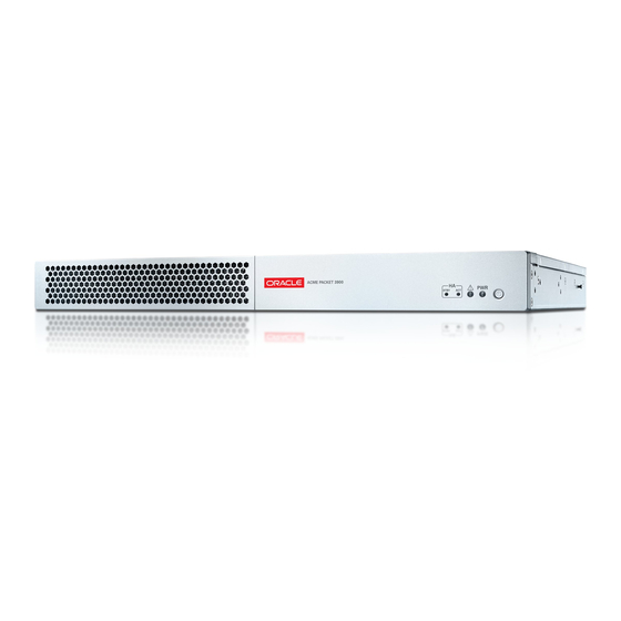
- Page 7 About This Guide Overview The Acme Packet 3900 System is a high performance, high capacity session border controller that optimally delivers interactive communications — voice, video, and multimedia sessions — across wireline, wireless, and cable IP network borders. With its compact single unit 1U design the Acme Packet 3900 System provides exceptional functionality in a tightly integrated system.
- Page 8 Revision History This section contains a revision history for this document. Date Description November 2016 Initial Release...
-
Page 9: Safety
To ensure general safety, follow the safety precautions listed in this section. Fan Module To avoid overheating the system, do not block the air inlets or the fan module, or otherwise obstruct airflow to the system. Keep the area around the Acme Packet 3900 System clean and clutter-free. Unit Maintenance... -
Page 10: Using This Guide
3900 System documentation. These warnings and cautions are designed to keep you safe and protect the Acme Packet 3900 System from damage. Precautions To protect yourself from harm and the Acme Packet 3900 System from damage, follow these electrical safety precautions: Precautions •... -
Page 11: Esd Safety
• Use a grounded ESD wrist or ankle strap when working on the Acme Packet 3900 to prevent static discharge. • To avoid damaging ESD-sensitive hardware, discharge all static electricity from your body before working directly with the Acme Packet 3900 chassis by touching a grounded object. -
Page 12: Component Overview
19” wide racks (up to 28” deep), with options for 23” wide racks. Mounting Hardware The Acme Packet 3900 is supported by a pair of cabinet slides that are affixed to an equipment rack by front and rear mounting flanges. The cabinet slides are adjustable for equipment racks of various depths. -
Page 13: System Processor
Control Panels This section describes the front and rear control panels of the Acme Packet 3900. Front Panel The Acme Packet 3900 front control panel provides easy access to several unit components. -
Page 14: Rear Panel
Control Panels High Availability Mode LEDs If you configure the Acme Packet 3900 as part of a High Availability pair, these LEDs will specify the current HA mode for the unit; whether the unit is in Standby or Active Mode. If the unit is not part of an HA pair these LEDs will not be lit. -
Page 15: T1/E1 Ports
The Acme Packet 3900 console port features one RJ45 port on the unit console. Because the Acme Packet 3900 does not employ any type of flow control on its RS-232 ports, only the RX, TX, and GND pins are used. The following table identifies the pin assignments and signal names/descriptions for the console connector. -
Page 16: Network Management Ports
Upon initial bootup of the Acme Packet 3900, the network management Ethernet ports are not configured. You must first connect to the Acme Packet 3900 over a serial connection before you can configure the management Ethernet ports for use. Set up the management interfaces using the physical and network interface configuration elements. -
Page 17: Usb3 Ports
Ethernet interfaces have a distance limitation of 328 feet (100 m), as defined by the FAST Ethernet standard, IEEE 802.3. USB3 Ports The two USB3 ports, located on the Acme Packet 3900 rear panel, are reserved for software-enabled applications, such as software updates. Signaling and Media Interfaces The signaling and media interfaces provide network connectivity for signaling and media traffic. - Page 18 Chapter 2 Media Cables mode and single mode — take a different fiber optic cable. You must use the proper fiber optic cable for each transceiver. Cables may be ordered from Oracle, or you may get them elsewhere. Cable Information Three different fiber optic cables used on the Acme Packet 3900 include: •...
-
Page 19: Power Components
Acme Packet 3900 can rely on only one functional power supply to sustain normal operation. A malfunctioning power supply must be removed and replaced as soon as possible. If the Acme Packet 3900 starts up with only one power supply, the alarm LED will blink continuously. -
Page 20: Dc Power
Oracle ships one region-specific power cord with each AC-power supply. DC Power The Acme Packet 3900 can be powered by central office –48 VDC operations with a DC-DC supply. The red handle on the front panel of the power supply is used to remove the power supply from the chassis. -
Page 21: Cooling Components
Fans Cooling Fans The Acme Packet 3900 chassis pulls cool ambient air into the chassis through two front-installed intake fans and exhausts heated air through perforated air outlets located along the rear of the chassis. To avoid overheating the system, do not block the air intake or exhaust or otherwise obstruct airflow to the unit in any way. -
Page 22: Installation
This chapter provides information about how to install the Acme Packet 3900 and its associated components. Shipped Parts Each Acme Packet 3900 ships in one box. Inside this box is the Acme Packet 3900 chassis and the accessory kit. The ordered modules are already installed in the chassis. -
Page 23: Pre-Installation Guidelines
Separate circuits should be available for each of the Acme Packet 3900 two power supplies. • The Acme Packet 3900 may only be powered by AC or DC circuits at one time; mixed power configurations are unsupported. • Never use extension cords when powering a Acme Packet 3900. -
Page 24: Other Safety Guidelines
Ensure that the equipment rack is securely bolted to the floor and that the equipment rack and components are properly grounded. • For AC power installations, use a regulating UPS to protect the Acme Packet 3900 from power surges, voltage spikes, and power failures. •... - Page 25 Chapter 3 Mounting Installation Mounting Hardware The hardware used for the Acme Packet 3900 mounting procedures include the following: • Front mounting flanges (2) for use with mounting slide rails, used to secure the chassis into the rack • Slide rail assembly (2), as shipped, with the chassis slide rail inserted into the equipment rack slide rail.
-
Page 26: Cabinet-Style 4-Post Chassis Installation
The mounting system consists of a slide rail mounted on each side of an equipment rack and a chassis slide rail mounted on each side of the Acme Packet 3900 chassis. Once the slide rails are installed on the equipment rack and chassis, the chassis can be slid into place by aligning the installed chassis slide rails along the guides on the equipment rack slide rails. - Page 27 Chapter 3 Cabinet-style 4-Post Chassis Installation Note: The following procedure presumes that the tapped hole size is #10-32. If alternate tapped holes are used, the customer must supply the proper screws. To install the slide rails to the front of a tapped-hole equipment rack: Locate the following components: •...
-
Page 28: Installing Slide Rails Into A Square-Hole Rack
Repeat Steps 2 and 6 for the other test equipment slide rail. Installing Slide Rails into a Square-Hole Rack This section explains how to mount the Acme Packet 3900 slide rail assembly into a square-hole equipment rack. The customer can use #10-32, 1/4-20, M5 or M6 cage nuts as an alternative, but the cage nuts will be customer-supplied along with the associated mounting screws for the cage nut selected. - Page 29 Chapter 3 Cabinet-style 4-Post Chassis Installation For each of the two holes in the slide rail flange, place a #10-32 screw through the mounting spacer, then through the slide rail flange, and finally through the square hole in the rack rail. Hold the nut bar behind the front rack rail.
-
Page 30: Installing The Chassis Flanges And Slide Rails
Line up the chassis slide rail with the Acme Packet 3900 side panel. Position hole #4 closest to the flange at the front of the Acme Packet 3900 chassis. Line up the keyhole slot on the slide rail with the keyhole button on the side of the Acme Packet 3900 and slide the rail slightly backwards to secure the slide. -
Page 31: Installing The Chassis In The Rack
Center-Mount 2-Post Chassis Installation Installing the Chassis in the Rack The Acme Packet 3900 is now ready to be installed into a 4-post equipment rack. To prevent personal injury or damage to the Acme Packet 3900, follow these guidelines: •... -
Page 32: Installing The Center-Mount Hardware
#6-32 x 1/4” flat head screws (6) Line up one chassis flange with the three tapped holes found along the center of the side of the Acme Packet 3900 chassis. The three screw holes of the chassis flange will only align in one direction. -
Page 33: Fan Module Installation
The chassis grounding terminals are located on the rear of the Acme Packet 3900 chassis, to the left of the USB ports. The Acme Packet 3900 ships with 2 kep nuts screwed onto the ground terminals. Use an 11/32” nut driver to remove and install these kep nuts. -
Page 34: Ac Power Cord Installation
Chapter 3 Ground and Power Cable Installation This section shows you how to install the grounding cable on your Acme Packet 3900. Important: Acme Packet 3900 equipment is suitable for installation as part of a Common Bonding Network (CBN). Note:... -
Page 35: Dc Power Cord Installation
Electrical Code (NEC) applies. To install the AC power cords in the Acme Packet 3900: Locate the two AC power cords shipped with your Acme Packet 3900. Choose one power supply to work on first. Connect one power cord to the power supply by inserting the 3-lead IEC-60320 plug into the IEC connector located on the power supply. -
Page 36: Cabling The Acme Packet System
To remove DC power cables from the Acme Packet 3900, reverse the previous steps in this procedure. Set the Power Pushbotton on the front of the Acme Packet 3900. The unit will start to boot. Cabling the Acme Packet System... -
Page 37: Chassis Console Cabling Procedure
Management Ports, Alarm Ports, and Console Port. Console Port The Acme Packet 3900 has one console port located on the rear panel. The Acme Packet 3900 ships with a console adapter that allows you to connect a standard DB-9 serial port to the Acme Packet 3900’s RJ45 console port. -
Page 38: Management Network Ports
RJ45. To create a physical T1 or E1 connection to the Acme Packet 3900 T1/E1 port, use the rear ports marked T1/E1 for a permanent connection to Wide Area Network (WAN). -
Page 39: Media And Signaling Network Interfaces
Chapter 3 Cabling the Acme Packet System Route the cable away from the Acme Packet 3900. Make sure that the Ethernet cables are not stretched tightly or subject to extreme stress. Repeat Steps 1 through 3 for each additional management Ethernet cable you will connect to your Acme Packet 3900. -
Page 40: Cabling For Ha Deployments
HA cabling. Insert one end of an Ethernet cable into either Mgmt1 or Mgmt2 on the rear panel of the Acme Packet 3900 A. The release tab on the RJ45 jack clicks into place when you insert it properly. -
Page 41: Dual Rear Interface Support
Chapter 3 Cabling for HA Deployments Dual Rear Interface Support To cable Acme Packet 3900s in an HA configuration using dual rear interface support: Insert one end of an Ethernet cable into Mgmt1 on the rear panel of Acme Packet 3900 A. -
Page 42: Startup
Acme Packet 3900. If the Acme Packet 3900 is already powered on, press the Enter key a few times to activate the console connection. When ACLI text is displayed on the screen, the console connection has been successfully created. -
Page 43: Powering On The Acme Packet
User Access Verification Password: If the Acme Packet 3900 completed booting before you connected to the console port, press the Enter key on the console keyboard a few times to activate the console connection. - Page 44 Superuser mode. ACMEPACKET# You can now begin configuring your Acme Packet 3900. Refer to the Configuration Guide to learn how to establish an IP address. If you have any questions about booting or powering on your system, please contact...
-
Page 45: Maintenance
– DSP modules System Shutdown Before you shut down or restart the Acme Packet 3900, ensure that there are no active calls in progress. The command to show active calls is “show sessions.” ACMEPACKET# show sessions Procedures to reroute call and network traffic around the Acme Packet 3900 are outside the scope of this guide. -
Page 46: Rejecting Incoming Calls
You may therefore wish to perform tasks that call for a reboot during off-peak maintenance hours. Rebooting the Acme Packet 3900 is required every time you upgrade with a new version of the software. -
Page 47: System Reset
Reboot this SD [y/n]?: y System Reset Resetting the Acme Packet 3900 via the reset pushbutton on the rear of the chassis performs a cold reboot. This action is the equivalent of disconnecting the power from the system and then reconnecting it. There is no orderly termination of tasks, and the system shuts down abruptly. - Page 48 Chapter 5 Standby State for HA Nodes There are two ways to determine the HA state of each Acme Packet 3900 in an HA pair. If you are in the same physical location as the Acme Packet 3900 you can view the HA LEDS on the front bottom right.
- Page 49 Chapter 5 Standby State for HA Nodes H248 Synchronized disabled Config Synchronized true Collect Synchronized disabled Radius CDR Synchronized disabled Rotated CDRs Synchronized disabled Active Peer Address 169.254.2.1 Redundancy Protocol Process (v3): State Standby Health Lowest Local Address 169.254.1.2:9090 1 peer(s) on 2 socket(s): SML-STIC-39001: v3, Active, health=100, max silence=1050 last received from 169.254.2.1...
-
Page 50: Maintenance With Power
Cooling maintenance encompasses cleaning the fan module and cleaning the air inlets on the front of the Acme Packet 3900 chassis. Cleaning the fan module requires that you remove the module itself. If you are not shutting down the Acme Packet 3900, this procedure must be performed quickly or else the system may overheat and cause packet processing to stop. -
Page 51: Clean The Air Inlets
Maintenance With Power Note: You can perform routine maintenance on the Acme Packet 3900 front panel fans and air filter with the unit normally installed in the equipment rack. Also, you do not need to remove the the power from the chassis. -
Page 52: Power Supply Removal And Replacement
Chapter 5 Maintenance With Power Remove the bezel. Unscrew the captive screws at the upper left and lower right corners of the fan you are replacing. Pull the fan out of the chassis. Move the fan to an ESD-safe location. Carefully align the pins on the back of the new fan with the holes in the chassis midplane and insert the fan into the slot. -
Page 53: Installing A Power Supply
Move the power supply to an ESD-safe location. Installing a Power Supply To install a power supply in the Acme Packet 3900 chassis: Insert the power supply into the empty power supply slot located on the rear panel of the chassis. -
Page 54: Optical Transceiver Removal And Replacement
Chapter 5 Maintenance With Power Optical Transceiver Removal and Replacement Your troubleshooting and diagnostics might reveal that the optical transceiver component of an optical physical interface card needs to be replaced. The optical transceiver serves two functions: • Converts electrical signals into optical signals used to communicate with other optical networking equipment. -
Page 55: Install An Optical Transceiver
Chapter 5 Maintenance With Power Holding the extended bale clasp latch, pull the optical transceiver fully out of its socket of the physical interface card. Install an Optical Transceiver To install an optical transceiver: Slide the replacement optical transceiver into the socket on the rear panel. Press on the face of the optical transceiver to seat it in the socket. -
Page 56: Copper Transceivers
Loosen the two thumbscrews on the rear panel. Loosen the two thumbscrews on the front panel. Pull the Acme Packet 3900 to the front of the rack until the chassis assembly stops. Push the chassis cover backwards about ½ inch. -
Page 57: Replacing Transcoder Dsp Modules
Replacing Transcoder DSP Modules Up to 5 transcoder DSP modules may be installed on the Acme Packet 3900 printed circuit board (PCB). There are slots for installing the transcoder DSP modules in one location on the Acme Packet 3900 PCB. -
Page 58: Guidelines
Chapter 5 Maintenance Without Power Guidelines Please read and follow these guidelines prior to installing or removing the transcoder DSP module: • The transcoder DSP module can be installed only in the designated location. • Ground yourself and follow proper ESD grounding procedures. •... -
Page 59: Removing The Transcoder Dsp Module
• Wear an ESD wrist strap. • On the Acme Packet 3900 or Acme Packet 3950/4900, remove the chassis cover. Use a fingertip to release the catch holding either end of the transcoder DSP module. Once the fasteners are detached from both sides of the transcoder DSP module, hold the center of the module between your finger and thumb and slowly remove the module. -
Page 60: Removing And Replacing The T1/E1 Tdm Module
Chapter 5 Maintenance Without Power • Wear an ESD wrist strap. Grasp the transcoder DSP module between your thumb and index finger and line up both sides of the module with the slot guides attached to the PCB. Using your thumb on your other hand, guide the module evenly into the slot guides located on each side as you lower the component into the connector. - Page 61 Chapter 5 Maintenance Without Power 5-17...
-
Page 62: Guidelines
Chapter 5 Maintenance Without Power Guidelines Read and follow these guidelines prior to installing or removing the TDM module: • Ground yourself and follow proper ESD grounding procedures. • Remove the transcoder TDM module from the shipped packaging. 5-18... -
Page 63: Remove The Tdm Module
Telecom label to attach to the chassis cover Remove the TDM Module Remove the Acme Packet 3900 cover. The T1/E1 TDM module is installed into the rear panel of the chassis and attached through a PCI Express x4 connector. The module is raised about a quarter of an inch off of the chassis PCB. - Page 64 Chapter 5 Maintenance Without Power looking from the inside of the chassis, the part of the metal to the left of the ports continues straight and is attached to the inside of the rear panel. To the right of the ports, the metal bends 90 degrees towards the rear of the chassis, and is inserted through the rear panel.
-
Page 65: Install The Tdm Module
Chapter 5 Maintenance Without Power When the module is fully disengaged, remove it from the chassis area to an ESD-safe location. Install the TDM Module Grasp the module by its edges. Orient it towards the plug and the rear panel of the chassis as you found the original module. - Page 66 Chapter 5 Maintenance Without Power 5-22...
-
Page 67: Specifications
For information regarding safety and regulatory certifications applicable to the Acme Packet 3900, refer to the Acme Packet Platforms Safety and Compliance Guide. Physical Specifications System Chassis Specifications This table lists the physical dimensions and weight of the Acme Packet 3900 chassis. Specification Description Height 1.72”... -
Page 68: Dc Power Supply Physical Dimensions
Chapter 6 Electrical Specifications DC Power Supply Physical Dimensions This table lists the physical dimensions and weight of the Acme Packet 3900 DC power supply. Specification Description Height 1.58” (4.01 cm) Width 3.4” (8.63 cm) Depth 9.33” (23.70 cm) Weight 2.34 lbs. -
Page 69: Connector Specifications
Connector Specifications Specification Description Temperature The Acme Packet 3900 is required to operate within the temperature range of: 0° C to +40° C, 32° F to 104° F (operating) -20° C to +65° C, -4° F to 149° F (storage) - Page 70 Chapter 6 Optical Transceiver Interface Module Specification Specification Single Mode (SX) Fiber Multi Mode (LX) Fiber Module Module Fiber type / Transmission 0.5 to 550 m — 50 μm MMF 300 m Distance 0.5 to 550 m — 62.5 μm MMF...
Need help?
Do you have a question about the Acme Packet 3900 and is the answer not in the manual?
Questions and answers