Table of Contents
Advertisement
Quick Links
Advertisement
Table of Contents

Related Manuals for Oracle Database Appliance X10 Series


Summary of Contents for Oracle Database Appliance X10 Series
- Page 1 Oracle® Database Appliance X10 Owner's Guide F92324-01 March 2024...
- Page 2 Oracle Corporation and its affiliates disclaim any liability for any damages caused by use of this software or hardware in dangerous applications.
-
Page 3: Table Of Contents
Oracle Database Appliance Setup Tasks Task Checklist Overview of Oracle Database Appliance Oracle Database Appliance X10 Series Components and Capabilities Oracle Database Appliance X10-S/X10-L Front and Back Panels Oracle Database Appliance X10-S/X10-L Front Panel Oracle Database Appliance X10-S/X10-L Back Panel... - Page 4 Safety Precautions When Rackmounting ESD Precautions Rack Compatibility Requirements Installing the System Into a Rack Installing Oracle Database Appliance X10-S/X10-L Into a Rack Contents of the Shipping Container Tools and Equipment Needed Stabilize the Rack for Installation Rackmount Kit Contents...
-
Page 5: Audience
Preface This guide provides a system overview and instructions for racking the Oracle Database Appliance. • Audience • Documentation Accessibility • Related Documents • Conventions Audience This document is intended for technicians, system administrators, and authorized service providers responsible for installing the Oracle Database Appliance. - Page 6 Preface Conventions The following text conventions are used in this document: Convention Meaning boldface Boldface type indicates graphical user interface elements associated with an action or terms defined in the text. italic Italic type indicates book titles, emphasis, or placeholder variables for which you supply particular values.
-
Page 7: Oracle Database Appliance Setup Tasks
Complete these tasks to setup Oracle Database Appliance. • Task Checklist List of steps with links to information describing the setup of Oracle Database Appliance. Task Checklist List of steps with links to information describing the setup of Oracle Database Appliance. -
Page 8: Overview Of Oracle Database Appliance
Learn about Oracle Database Appliance model supported components,capabilities and features. • Oracle Database Appliance X10 Series Components and Capabilities See a listing of the various supported capabilities for the Oracle Database Appliance X10 series. • Oracle Database Appliance X10-S/X10-L Front and Back Panels See views and descriptions of front and back panel features for Oracle Database Appliance X10-S/X10-L. - Page 9 Chapter 2 Oracle Database Appliance X10 Series Components and Capabilities Component Oracle Database Oracle Database Oracle Database Appliance X10-S Appliance X10-L Appliance X10-HA Memory 256 GB – four 64 GB low- 512 GB – eight 64 GB low- 512 GB – eight 64 GB low-...
- Page 10 Chapter 2 Oracle Database Appliance X10 Series Components and Capabilities Component Oracle Database Oracle Database Oracle Database Appliance X10-S Appliance X10-L Appliance X10-HA PCI Express (PCIe) I/O Nine external low-profile Nine external low-profile Nine external low-profile slots PCIe Gen-5 slots. However, PCIe Gen-5 slots.
-
Page 11: Oracle Database Appliance X10-S/X10-L Front And Back Panels
Oracle Integrated Lights Oracle Integrated Lights Out Manager (ILOM) 5.1. Out Manager (ILOM) 5.1. Out Manager (ILOM) 5.1. Oracle Database Appliance X10-S/X10-L Front and Back Panels See views and descriptions of front and back panel features for Oracle Database Appliance X10-S/X10-L. -
Page 12: Oracle Database Appliance X10-S/X10-L Front Panel
Chapter 2 Oracle Database Appliance X10-S/X10-L Front and Back Panels This section describes Oracle Database Appliance X10-S/X10-L front and back panels. If you have some other Oracle Database Appliance model, select the appropriate link listed in Overview of Oracle Database Appliance. -
Page 13: Oracle Database Appliance X10-S/X10-L Back Panel
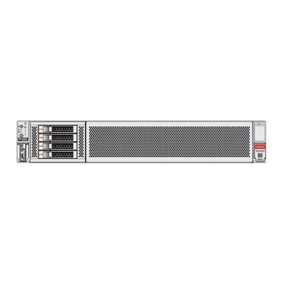
Service Information QR Code Oracle Database Appliance X10-S/X10-L Back Panel See an illustration and description of Oracle Database Appliance X10-S/X10-L back panel features. The following figure shows the components on the back panel of an Oracle Database Appliance X10-S/X10-L. - Page 14 Chapter 2 Oracle Database Appliance X10-S/X10-L Front and Back Panels Callout Description Power Supply (PS) 1 with fan module Power Supply (PS) 1 status indicators: Service Required LED: amber, AC OK LED: green Power Supply 1 (PS1) AC Power Inlet...
-
Page 15: Oracle Database Appliance X10-Ha Front And Back Panels
Oracle ILOM service processor Oracle Database Appliance X10-HA Front and Back Panels See views and descriptions of front and back panel features for Oracle Database Appliance X10-HA. This section describes Oracle Database Appliance X10-HA front and back panels. If... -
Page 16: Oracle Database Appliance X10-Ha Front Panel
Oracle Database Appliance X10-HA includes two server nodes and an Oracle DE3-24C storage shelf. The entire unit occupies 8RU. The optional storage expansion shelf requires an additional 4RU, increasing the total to 12RU. The following figure shows the front of Oracle Database Appliance X10-HA with an optional storage expansion shelf. Callout... -
Page 17: Server Node Front Panel Features
Server Node Front Panel Features See an illustration and listing of Oracle Database Appliance X10-HA server node front panel features. The following figure shows the components on the front panel of an Oracle Database Appliance X10-HA server node. Callout Description... -
Page 18: Storage Shelf Front Panel Features
For details, see Technical Support. Storage Shelf Front Panel Features See an illustration and listing of Oracle Database Appliance X10-HA storage shelf front panel features. The following figure shows the Oracle Database Appliance X10-HA storage shelf front panel features. -
Page 19: Oracle Database Appliance X10-Ha Back Panel
Drive fault indicator Drive power/activity indicator Oracle Database Appliance X10-HA Back Panel See an illustration and listing of Oracle Database Appliance X10-HA back panel features. This section describes the back panel features for Oracle Database Appliance X10- The following figure shows the Oracle Database Appliance X10-HA. - Page 20 Storage shelf (DE3-24C) Optional storage expansion shelf (DE3-24C) • Server Node Back Panel Features See an illustration and listing of Oracle Database Appliance X10-HA server node back panel features. • Storage Shelf Back Panel Features See an illustration and listing of Oracle Database Appliance X10-HA storage shelf back panel features.
-
Page 21: Server Node Back Panel Features
Server Node Back Panel Features See an illustration and listing of Oracle Database Appliance X10-HA server node back panel features. The following figure shows the components on the back panel of an Oracle Database Appliance X10-HA server node. Callout Description... -
Page 22: Storage Shelf Back Panel Features
SER MGT port: RJ-45 serial port used to connect to the Oracle ILOM service processor Storage Shelf Back Panel Features See an illustration and listing of Oracle Database Appliance X10-HA storage shelf back panel features. The following figure shows the Oracle Database Appliance X10-HA storage shelf back features. - Page 23 Chapter 2 Oracle Database Appliance X10-HA Front and Back Panels Callout Description AC power indicator Fan fail indicator Power supply status indicator DC power fail indicator Power Supply with fan module 0 Note: The on/off switch on the power supply is non- functional on this product.
-
Page 24: Oracle Database Appliance Specifications
Oracle Database Appliance Specifications This section describes the physical, electrical and environmental specifications for the various Oracle Database Appliance models. • Physical Specifications for Oracle Database Appliance X10 Series • Electrical Specifications for Oracle Database Appliance X10 Series • Environmental Specifications for Oracle Database Appliance X10 Series... - Page 25 Chapter 2 Oracle Database Appliance Specifications Electrical Specifications for Oracle Database Appliance X10 Series Item Oracle Database Appliance Oracle Database Appliance Oracle Database Appliance X10-S X10-L X10-HA Server power 1400W at 200-240 VAC, 1400W at 200-240 VAC, 1400W at 200-240 VAC,...
-
Page 26: Technical Support
Chapter 2 Technical Support Item Oracle Database Appliance Oracle Database Appliance Oracle Database Appliance X10-S X10-L X10-HA Operating 10% to 90% relative humidity, 10% to 90% relative humidity, 10% to 90% relative humidity, humidity noncondensing, short term – noncondensing, short term –... - Page 27 TLI, do one of the following: • Look on another component (server node or storage shelf) of the appliance. All factory-bundled server nodes of Oracle Database Appliance have the same TLI numbers. • Slide a server node partway out on its rails, just far enough to see the TLI.
-
Page 28: Site Preparation
Site Preparation Learn about site preparation requirements for the Oracle Database Appliance before installing it into a rack and cabling it. • Prepare Your Site Use this procedure before installing the appliance into a rack. Prepare Your Site Use this procedure before installing the appliance into a rack. - Page 29 System failure. All items in a shipment are designed to be used together as a single system. Do not mix components from different shipments; this could cause the system to fail. It should contain: Oracle Database Appliance X10-S/X10-L Oracle Database Appliance X10-HA • Preconfigured system •...
-
Page 30: Installing Oracle Database Appliance Into A Rack
Procedures describing how to install the various Oracle Database Appliance models into a rack. Task Overview Tasks to perform when installing various models of Oracle Database Appliance into a rack. Follow the appropriate procedures to rack mount your system. Note: These procedures describe how to install the appliance into a rack. -
Page 31: Optional Component Installation
DIMM memory kits: – For Oracle Database Appliance X10-S, which comes with 256 GB (four 64 GB registered DIMMs), you have the option of expanding to 512 GB or 768 GB. Memory kits come in sets of four 64 GB registered DIMMs. - Page 32 • Optional network cards: For Oracle Database Appliance X10 series, you have the option of ordering up to two additional public network PCIe cards per system (or per node for the X10-HA). Supported network cards include the Oracle Dual Port 25Gb Ethernet Adapter and the Oracle Quad Port 10GBase-T Adapter.
-
Page 33: Safety Precautions When Rackmounting
Deployment and User's Guide for instructions on cabling and software configuration. Safety Precautions When Rackmounting Learn about safety precautions during rack installation for Oracle Database Appliance. This section describes safety precautions you must follow when installing the server into a rack. -
Page 34: Esd Precautions
ESD Precautions Learn about electrostatic discharge precautions during rack installation for Oracle Database Appliance. Caution: Equipment damage. To prevent damage from electrostatic discharge, use the following precautions when installing or servicing components. -
Page 35: Installing The System Into A Rack
Storage shelf dimensions Oracle Database Appliance X10 Series Installing the System Into a Rack Procedures describing how to install the various Oracle Database Appliance models into a rack. Caution: Personal injury or equipment damage. Always load equipment into a rack from the bottom up so that it will not become top-heavy and tip over. -
Page 36: Installing Oracle Database Appliance X10-S/X10-L Into A Rack
Install the Cable Management Arm (Optional) Contents of the Shipping Container Inspect the shipping cartons of your Oracle Database Appliance system for evidence of physical damage. If a shipping carton appears damaged, request that the carrier's agent be present when the carton is opened. Keep all contents and packing material for the agent's inspection. -
Page 37: Rackmount Kit Contents
Chapter 4 Installing the System Into a Rack Refer to your rack cabinet documentation for more detailed instructions. When unpacking at the installation site, verify that the rack cabinet leveling feet are up before moving the rack cabinet. Remove the front and rear doors of the rack cabinet if they interfere with the installation. -
Page 38: Mark The Rackmount Location
Mark the Rackmount Location Identify the location in the rack where you want to place the server. Oracle Database Appliance server requires two rack units (2U). Use the Rackmounting Template to identify the correct mounting holes for the slide-rails. - Page 39 Chapter 4 Installing the System Into a Rack Caution: Always load equipment into a rack from the bottom up so that the rack does not become top-heavy and tip over. Extend the rack anti-tilt bar to prevent the rack from tipping during equipment installation. Ensure that there is at least two rack units (2U) of vertical space in the rack cabinet to install the server.
-
Page 40: Attach The Ac Power Cables And Server Slide-Rails To The Rack
Chapter 4 Installing the System Into a Rack Attach the AC Power Cables and Server Slide-Rails to the Rack Use this procedure to attach the server slide-rail assemblies to the rack. Note: Be sure to install the server right-angle AC power cables that came with your system. - Page 41 Chapter 4 Installing the System Into a Rack Call Out Description Slide-rail Ball-bearing track Ball-bearing locking mechanism Starting with either the left or right side of the rack, align the back of the slide-rail assembly against the inside of the back rack rail, and push until the assembly locks into place with an audible click.
-
Page 42: Install The Server Into The Slide-Rail Assemblies
Chapter 4 Installing the System Into a Rack Align the front of the slide-rail assembly against the outside of the front rack rail, and push until the assembly locks into place with an audible click. Repeat Step 2 through Step 4 to attach the slide-rail assembly to the other side of the rack. - Page 43 Chapter 4 Installing the System Into a Rack Position the server so that the back ends of the mounting brackets are aligned with the slide-rail assemblies that are mounted in the rack. Insert the mounting brackets into the slide-rails, and then push the server into the rack until the mounting brackets are flush with the slide-rail stops (approximately 30 cm or 12 inches).
-
Page 44: Install The Cable Management Arm (Optional)
Chapter 4 Installing the System Into a Rack Caution: Before you install the optional cable management arm verify that the server is securely mounted in the rack and that the slide-rail locks are engaged with the mounting brackets. Do one of the following: •... - Page 45 Chapter 4 Installing the System Into a Rack Call Out Description Connector A Front slide bar Velcro straps (6) Connector B Connector C Connector D Slide-rail latching bracket (used with connector D) Back slide bar Server flat cable covers Server round cable covers (optional) Prepare the CMA for installation.
- Page 46 Chapter 4 Installing the System Into a Rack Note: Ensure that the two Velcro straps located on the front slide bar are threaded through the opening in the top of the slide bar, as shown in the illustration in Step 1. This prevents the Velcro straps from interfering with the expansion and contraction of the slide bar when the server is extended out of the rack and returned to the rack.
- Page 47 Chapter 4 Installing the System Into a Rack Call Out Description Connector A tab Left slide-rail front slot To install CMA connector B into the right slide-rail: Insert CMA connector B into the front slot on the right slide-rail until it locks into place with an audible click [1 and 2].
- Page 48 Chapter 4 Installing the System Into a Rack Call Out Description Connector C locking spring Insert connector C into the right slide-rail until it locks into place with an audible click [2 and 3]. Gently tug on the right side of the CMA back slide bar to verify that connector C is properly seated.
- Page 49 Chapter 4 Installing the System Into a Rack To install CMA connector D into the left slide-rail: While holding the slide-rail latching bracket in place, insert connector D and its associated slide-rail latching bracket into the left slide-rail until connector D locks into place with an audible click [1 and 2].
- Page 50 Chapter 4 Installing the System Into a Rack Gently tug on the four CMA connection points to ensure that the CMA connectors are fully seated before you allow the CMA to hang by its own weight. To verify that the slide-rails and the CMA are operating properly before routing cables through the CMA: Ensure that the rack anti-tilt bar is extended to prevent the rack from tipping forward when the server is extended.
- Page 51 Chapter 4 Installing the System Into a Rack Continue pushing the server into the rack until the slide-rail locks (on the front of the server) engage the slide-rail assemblies. You hear a click when the server is in the normal rack position. Retract the rack anti-tilt mechanism back to its normal position.
-
Page 52: Installing Oracle Database Appliance X10-Ha Into A Rack
Installing Oracle Database Appliance X10-HA Into a Rack Procedures describing how to install Oracle Database Appliance X10-HA into a rack. Caution: System Failure. Oracle Database Appliance is shipped with matched sets of components that must be installed together. -
Page 53: Contents Of The Shipping Container
Ensure that appliance components bundled together from the factory are connected together. • Tools and Equipment Needed A listing of the tools you will need to install Oracle Database Appliance X10-HA. • Stabilize the Rack for Installation • Apply Labels to Server Nodes Complete this task to apply server node labels before installing the appliance into a rack. -
Page 54: Installation Sequence
Understand the proper installation sequence when installing an Oracle Database Appliance X10-HA into a rack. Always install equipment in a rack starting at the bottom and working upwards. For Oracle Database Appliance X10-HA, install the equipment in the following order: Storage expansion shelf, if equipped (lowest available rack space). -
Page 55: Tools And Equipment Needed
Chapter 4 Installing the System Into a Rack Tools and Equipment Needed A listing of the tools you will need to install Oracle Database Appliance X10-HA. Obtain the following tools and equipment before beginning the installation of Oracle Database Appliance X10-HA. -
Page 56: Install The Storage Shelf Into A Rack
Storage shelf Install the Storage Shelf Into a Rack Describes how to install an Oracle Database Appliance X10-HA storage shelf into a rack. The Oracle Database Appliance X10-HA uses the Oracle Storage Drive Enclosure DE3-24C as its storage shelf. The storage shelf requires four standard mounting units (4RU) of vertical space in the cabinet. - Page 57 Chapter 4 Installing the System Into a Rack Note: The rail kit included with the shelf can only be used with EIA compliant 9.5 mm square hole racks or 7.0 mm diameter round hole racks. • Observe all precautions in Safety Precautions When Rackmounting Starting at the bottom of the cabinet, locate the appropriate rack unit (RU) height.
- Page 58 Chapter 4 Installing the System Into a Rack Callout Description Six rear 10-32 7mm shipping screws (2 are spares) Four round 7mm 10-32 cage nuts per set (2 are spares). Only one set is required, either square or round. Cage nut tool Four square 9.5mm 10-32 cage nuts per set (2 are spares).
- Page 59 Chapter 4 Installing the System Into a Rack Install one screw through the rack and into the rear of each rail. The following figure shows how to secure the storage shelf rails to the rack: Install the front cage nuts. Caution: Installing the storage shelf without the front cage nuts will cause the storage shelf to be unstable.
- Page 60 Chapter 4 Installing the System Into a Rack Callout Description Cage nuts Cage nut installation template Cage nut tool Use the template [2] to determine cage nut placement. Retrieve a cage nut and hook one lip of the nut into the appropriate rail hole [1]. Insert the tip of the cage nut insertion tool through the rail hole [3] and hook the other lip of the cage nut.
- Page 61 Chapter 4 Installing the System Into a Rack Carefully slide the shelf into the cabinet. Ensure that the shelf is fully seated within the rails. If removing the shelf to reseat it, support it at all times. Secure the front of the shelf using the four captive securing screws [1 - 4]. The following figure shows how to secure the front of the storage shelf: To secure the storage shelf in the rack for shipping, install a screw in each rear storage shelf chassis ear.
-
Page 62: Add A Storage Expansion Shelf To An Existing System
Unless noted, it is not necessary to shut down your system to complete this task. Please note the following exceptional conditions: • The storage expansion shelf normally sits at the bottom of Oracle Database Appliance, beneath the storage shelf. However, since racks should always be provisioned from the 4-33... -
Page 63: Rackmount Kit Contents
Chapter 4 Installing the System Into a Rack bottom up, that space might be unavailable. In these cases, to avoid re- rackmounting the entire system, it can be placed above the server nodes, or even in a different rack. • The Top Level Identifier (TLI) on the storage expansion shelf will not match the rest of the system as described in Verify Component... -
Page 64: Mark The Rackmount Location
Mark the Rackmount Location Identify the location in the rack where you want to place the server. Oracle Database Appliance server requires two rack units (2U). Use the Rackmounting Template to identify the correct mounting holes for the slide-rails. - Page 65 Chapter 4 Installing the System Into a Rack Caution: Always load equipment into a rack from the bottom up so that the rack does not become top-heavy and tip over. Extend the rack anti-tilt bar to prevent the rack from tipping during equipment installation. Ensure that there is at least two rack units (2U) of vertical space in the rack cabinet to install the server.
-
Page 66: Attach The Ac Power Cables And Server Slide-Rails To The Rack
Chapter 4 Installing the System Into a Rack Attach the AC Power Cables and Server Slide-Rails to the Rack Use this procedure to attach the server slide-rail assemblies to the rack. Note: Be sure to install the server right-angle AC power cables that came with your system. - Page 67 Chapter 4 Installing the System Into a Rack Call Out Description Slide-rail Ball-bearing track Ball-bearing locking mechanism Starting with either the left or right side of the rack, align the back of the slide-rail assembly against the inside of the back rack rail, and push until the assembly locks into place with an audible click.
-
Page 68: Install The Server Into The Slide-Rail Assemblies
Chapter 4 Installing the System Into a Rack Align the front of the slide-rail assembly against the outside of the front rack rail, and push until the assembly locks into place with an audible click. Repeat Step 2 through Step 4 to attach the slide-rail assembly to the other side of the rack. - Page 69 Chapter 4 Installing the System Into a Rack Position the server so that the back ends of the mounting brackets are aligned with the slide-rail assemblies that are mounted in the rack. Insert the mounting brackets into the slide-rails, and then push the server into the rack until the mounting brackets are flush with the slide-rail stops (approximately 30 cm or 12 inches).
-
Page 70: Install The Cable Management Arm (Optional)
Chapter 4 Installing the System Into a Rack Caution: Before you install the optional cable management arm verify that the server is securely mounted in the rack and that the slide-rail locks are engaged with the mounting brackets. Do one of the following: •... - Page 71 Chapter 4 Installing the System Into a Rack Call Out Description Connector A Front slide bar Velcro straps (6) Connector B Connector C Connector D Slide-rail latching bracket (used with connector D) Back slide bar Server flat cable covers Server round cable covers (optional) Prepare the CMA for installation.
- Page 72 Chapter 4 Installing the System Into a Rack Note: Ensure that the two Velcro straps located on the front slide bar are threaded through the opening in the top of the slide bar, as shown in the illustration in Step 1. This prevents the Velcro straps from interfering with the expansion and contraction of the slide bar when the server is extended out of the rack and returned to the rack.
- Page 73 Chapter 4 Installing the System Into a Rack Call Out Description Connector A tab Left slide-rail front slot To install CMA connector B into the right slide-rail: Insert CMA connector B into the front slot on the right slide-rail until it locks into place with an audible click [1 and 2].
- Page 74 Chapter 4 Installing the System Into a Rack Call Out Description Connector C locking spring Insert connector C into the right slide-rail until it locks into place with an audible click [2 and 3]. Gently tug on the right side of the CMA back slide bar to verify that connector C is properly seated.
- Page 75 Chapter 4 Installing the System Into a Rack To install CMA connector D into the left slide-rail: While holding the slide-rail latching bracket in place, insert connector D and its associated slide-rail latching bracket into the left slide-rail until connector D locks into place with an audible click [1 and 2].
- Page 76 Chapter 4 Installing the System Into a Rack Gently tug on the four CMA connection points to ensure that the CMA connectors are fully seated before you allow the CMA to hang by its own weight. To verify that the slide-rails and the CMA are operating properly before routing cables through the CMA: Ensure that the rack anti-tilt bar is extended to prevent the rack from tipping forward when the server is extended.
- Page 77 Chapter 4 Installing the System Into a Rack Continue pushing the server into the rack until the slide-rail locks (on the front of the server) engage the slide-rail assemblies. You hear a click when the server is in the normal rack position. Retract the rack anti-tilt mechanism back to its normal position.
- Page 78 Chapter 4 Installing the System Into a Rack Ensure that the secured cables do not extend above the top or below the bottom of the server to which they are attached. Otherwise, the cables might snag on other equipment installed in the rack when the server is extended from the rack or returned to the rack.
-
Page 79: Index
Adding storage expansion shelf, 4-33 antistatic grounding strap, electrostatic discharge, precautions, back panel features fans Oracle Database Appliance X10-S/X10- supported, front panel server node features features Oracle Database Appliance X10-HA, Oracle Database Appliance X10-S/X10- 2-14 storage shelf features server node features... - Page 80 2-12 Oracle Database Appliance, 4-7, 4-26 Oracle Database Appliance X10-HA, rackmount 2-15 kit contents, 4-8, 4-34 view of front panel marking the location, 4-9, 4-35 Oracle Database Appliance X10-HA, 2-9, 2-11 support , 2-19 for product, 2-19 supported, Index-2...
- Page 81 Index tools (continued) required for racking (continued) technical support Oracle Database Appliance X10-S/X10- See support TLI (Top Level Identifier) label location Oracle Database Appliance X10-HA, 4-25 tools supported, required for racking Oracle Database Appliance X10-HA, 4-26 video supported, Index-3...
Need help?
Do you have a question about the Database Appliance X10 Series and is the answer not in the manual?
Questions and answers