Table of Contents
Advertisement
Quick Links
Advertisement
Table of Contents

Related Manuals for Fuji Electric FSJ


Summary of Contents for Fuji Electric FSJ
- Page 2 PREFACE Thank you for purchasing Fuji Electric’s ultrasonic flowmeter. This instruction manual describes ultrasonic flow transmitter (FSJ) and detector (FSX) installation, operation, inspection, and maintenance, and should be read carefully before use. First read this instruction manual carefully until an adequate understanding is acquired, and then proceed to installation, operation, and maintenance of the flow meter.
- Page 3 -ii-...
-
Page 4: Safety Precautions
SAFETY PRECAUTIONS Before using this product, read the following safety precautions and use the product correctly. The following items are important for safe operation and must be fully observed. These safety precautions are ranked in 2 levels; "DANGER" and "CAUTION". Warning/Symbol Meaning Incorrect handling of the device may result in death or serious injury. - Page 5 Caution on mounting and piping ● This unit is not explosion-proof type. Do not use it in a place with explosive gases. Otherwise, it may result in serious accidents such as explosion, fire, etc. ● The unit should be installed in a place conforming to the installation requirements noted in this instruction manual.
- Page 6 “Section 6.2.2.How to measure the insulation resistance” described in this manual. ● Blown fuses must be replaced. ● Be sure to contact Fuji Electric when replacement is required. Do not attempt to replace fuses by yourself. -v-...
-
Page 7: Caution On Installation Location
CAUTION ON INSTALLATION LOCATION (1) A place where ambient temperature and humidity are -20 to +60°C and 95% RH or less for flow transmitter (FSJ). (2) Indoor or outdoor locations where there is no exposure to direct sunlight or wind and rain. -
Page 8: Table Of Contents
Temperature unit ꞏꞏꞏꞏꞏꞏꞏꞏꞏꞏꞏꞏꞏꞏꞏꞏꞏꞏꞏꞏꞏꞏꞏꞏꞏꞏꞏꞏꞏꞏꞏꞏꞏꞏꞏꞏꞏꞏ 38 1.4. Name and function of each part ꞏꞏꞏꞏꞏꞏꞏꞏꞏꞏꞏꞏꞏꞏꞏꞏꞏꞏꞏꞏꞏꞏꞏꞏꞏꞏ 4 4.8. Output Setting ꞏꞏꞏꞏꞏꞏꞏꞏꞏꞏꞏꞏꞏꞏꞏꞏꞏꞏꞏꞏꞏꞏꞏꞏꞏꞏꞏꞏꞏꞏꞏꞏꞏꞏꞏꞏꞏꞏꞏꞏꞏꞏꞏꞏꞏꞏꞏ 39 Flow transmitter (FSJ) ꞏꞏꞏꞏꞏꞏꞏꞏꞏꞏꞏꞏꞏꞏꞏꞏꞏꞏꞏꞏꞏꞏꞏꞏꞏꞏꞏꞏꞏꞏꞏꞏꞏ 4 Setting of flow rate range ꞏꞏꞏꞏꞏꞏꞏꞏꞏꞏꞏꞏꞏꞏꞏꞏꞏꞏꞏꞏꞏꞏꞏꞏꞏꞏꞏ 39 Detector (FSX) ꞏꞏꞏꞏꞏꞏꞏꞏꞏꞏꞏꞏꞏꞏꞏꞏꞏꞏꞏꞏꞏꞏꞏꞏꞏꞏꞏꞏꞏꞏꞏꞏꞏꞏꞏꞏꞏꞏꞏꞏꞏꞏ 5 4.8.1.1. Volume flow range (single range) ꞏꞏꞏꞏꞏꞏꞏꞏꞏꞏꞏ 39 4.8.1.2. - Page 9 Analog input calibration method ꞏꞏꞏꞏꞏꞏꞏꞏꞏꞏꞏꞏꞏꞏꞏꞏꞏ 83 Analog input check method ꞏꞏꞏꞏꞏꞏꞏꞏꞏꞏꞏꞏꞏꞏꞏꞏꞏꞏꞏꞏꞏꞏ 84 Confirming the input temperature ꞏꞏꞏꞏꞏꞏꞏꞏꞏꞏꞏꞏꞏꞏꞏ 85 Test mode (simulated flow rate output) ꞏꞏꞏꞏꞏꞏꞏꞏ 86 Serial transmission (RS-485) ꞏꞏꞏꞏꞏꞏꞏꞏꞏꞏꞏꞏꞏꞏꞏꞏꞏꞏꞏꞏ 88 Setting the ID No. ꞏꞏꞏꞏꞏꞏꞏꞏꞏꞏꞏꞏꞏꞏꞏꞏꞏꞏꞏꞏꞏꞏꞏꞏꞏꞏꞏꞏꞏꞏꞏꞏꞏ 90 Confirming the software version ꞏꞏꞏꞏꞏꞏꞏꞏꞏꞏꞏꞏꞏꞏꞏ 90 LCD backlight setting ꞏꞏꞏꞏꞏꞏꞏꞏꞏꞏꞏꞏꞏꞏꞏꞏꞏꞏꞏꞏꞏꞏꞏꞏꞏꞏꞏꞏ...
-
Page 10: Product Outline
1.2. Checking delivered items After opening the package, check if all following parts are present. Note that the delivered parts vary according to the model. Flow transmitter (FSJ) Detector (FSX) and dedicated signal cable (FLYE) Flow transmitter main unit ꞏꞏꞏꞏꞏꞏꞏꞏꞏꞏꞏꞏꞏꞏꞏꞏꞏꞏꞏꞏꞏꞏꞏꞏꞏꞏꞏꞏꞏꞏꞏꞏꞏꞏ 1 set Pre-amplifier unit ×... -
Page 11: Check On Type And Specifications
1.3. Check on type and specifications The type and specifications of product are indicated on the specifications plate mounted on the flow transmitter and detector frame. Check that they represent the type you ordered, referring to the following code symbols. <Flow transmitter (FSJ)> -2-... - Page 12 < Detector (FSX)> < Dedicated signal cable > -3-...
-
Page 13: Name And Function Of Each Part
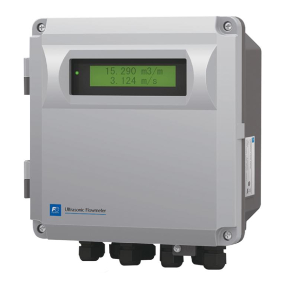
1.4. Name and function of each part Flow transmitter (FSJ) Name Description Wiring connection port This is a wiring connection port for the power cable, input/output signal cable, communication cable, or resistance temperature detector cable. Signal cable connector This is a dedicated signal cable connector. -
Page 14: Detector (Fsx)
Detector (FSX) Name Description Sensor unit Sends and receives ultrasonic waves. Sensor mounting bracket Secures the sensor unit to pipes. Noise elimination frame Eliminates acoustic noise which propagates to pipe walls. Transfers transmission and receipt signals. Connect to the pre- Sensor cable amplifier unit. -
Page 15: Operation Preparation
NG (LED display is red) Section Checking the RAS information Section 6.3 Error and remedy 6.3.1.3 (LED display is green) Contact Fuji Electric’s service representative. Section Check A, B for the Basic operation Output limit 4.8.1.5 7th digit of code... -
Page 16: Tools Required For Installation
2.2. Tools required for installation Tools required for installation (list) Tools Specification Process Width across flat: 13 mm Converter installation Spanner Width across flat: 21 mm Sensor mounting, bracket mounting Width across flat: 10 mm Sensor mounting Width across flat: 10 mm Socket wrench or spanner Pre-amplifier mounting Width across flat: 7 mm... -
Page 17: Installation
(1) A place where ambient temperature and humidity are -20 to +60°C and 95% RH or less for flow transmitter (FSJ) (2) A place not exposed to direct sunshine nor inclement weather. -
Page 18: Installation Location Of Flow Transmitter
3.1. Installation location of flow transmitter Secure at least 100 mm of space between the flow transmitter and nearby wall. Also secure a space of opening the front cover in case of maintenance. Allow space for cable wiring under the case. Fig. -
Page 19: Detector Installation Location
3.2. Detector installation location The detector mounting location, in other words on pipe at which flow rate is measured, will greatly affect measurement accuracy, and therefore a location which satisfies the following conditions should be selected. ① Location with straight pipe indicated in "3.2.1 Conditions on straight pipe“ ②... -
Page 20: Conditions On Straight Pipe
Conditions on straight pipe -11-... -
Page 21: Mounting Orientation
Mounting orientation This instrument can be mounted vertically, horizontally, or at any other angle, however, it is necessary to pay attention to the following items. (1) If installing on a horizontal pipe, mount sensors within ±45° of the center plane. If installing on a vertical pipe, sensors may be mounted anywhere on the outer perimeter. -
Page 22: Installation Of Flow Transmitter
3.3. Installation of flow transmitter The flow transmitter may be mounted on a wall or 2B pipe stand (option). Wall mounting For wall mounting, use four M8 bolts. Drill holes according to the mounting hole dimensions shown below, and fasten the flow transmitter using the M8 bolts. -13-... -
Page 23: Pipe Stand Mounting
2B pipe stand mounting When mounting on 2B pipe, be sure to use a complete set of fixtures (U bolt, support fixture, plain washer, spring washer, nut) furnished if optionally designated. Tighten the nut by hand. If any support fixture is not used or if the assembly is excessively tightened by tool, the wall mounting fixture may be deformed. -
Page 24: Flow Transmitter Wiring
Use a dedicated signal cable (FLYE) for the signal cable between the pre-amplifier unit and flow transmitter (FSJ). Furthermore, do not connect a relay cable to any part of the dedicated signal cable. Be sure to pass the dedicated signal cable between the pre-amplifier unit and flow transmitter along a metal conduit. -
Page 25: Wiring To Each Terminal
Wiring to each terminal Carry out wiring to each terminal according to the following figure. Note1) Terminal block is insertion type to connect a cable. Use bar terminal as crimp-style terminals. Note2) Be sure to ground the external grounding terminal (M4). (Class D grounding) Note3) For input/output signal, use multiple core cable as required. -
Page 26: How To Connect To Terminal Block
How to connect to terminal block 3.4.5.1. Cable treatment Although the cables can be connected to the terminals with bare wire, we recommend using bar terminal (ferrule) for connecting cables. Usable wiring materials Wire size (mm Type φD1(mm) φD2(mm) H0.5/16 0.75 H0.75/16 H1/16... -
Page 27: How To Connect To Power Supply/Signal
3.4.5.2. How to connect to power supply/signal terminal block Please prepare a flathead screwdriver (head size: 0.6 × 3.5mm) or a small-sized Phillips head screwdriver so as to tighten the cable. (1) Pull off the cable socket from the plug on the substrate with holding the right side of the socket by hand. (2) If cable entry is closed, turn the screw counterclockwise to open. -
Page 28: Method For Connecting To Communication Board And Temperature Measurement Board Terminal Block
3.4.5.3. Method for connecting to communication board and temperature measurement board terminal block In the case of rod terminals, push in until they hit against the terminal block hole, and ensure that they do not come out. In the case of bare wire, press the clamp with a finger or with tweezers, etc. to open the insertion port, push the bare wire in until it hits against the terminal block hole, release the clamp to secure the wire, and ensure that it does not come out. -
Page 29: Parameters
4. PARAMETERS 4.1. Description of display/setting unit Display unit and setting unit are as shown below. Display/setting unit LCD display Setting key -20-... -
Page 30: Description Of Display/Setting Unit
Description of display/setting unit ○ LCD display: Displays measurement values and setting values (16 digits × 2 rows). “Measurement display” The data area displays a maximum of 8 digits, including the decimal point. If the value exceeds the number of display digits, “<” is displayed at the highest digit. If the value exceeds the range, “OVERRANGE”... -
Page 31: Composition Of Key Operation
4.2. Composition of key operation -22-... - Page 32 -23-...
- Page 33 -24-...
-
Page 34: Parameter Initial Value List
4.3. Parameter initial value list Factory-set value is shown below. (When parameter setting is not provided) Setting unit Setting range Initial value Setting range Setting value ID No. 0000 to 9999 0000 LANGUAGE No. of menu: 5 English English, Japanese, German, French, Spanish SYSTEM UNIT No. - Page 35 Setting unit Setting range Initial value Setting range Setting value OUTPUT LIMIT LOW -20 to 0% -20% OUTPUT LIMIT HIGH 100 to 120% 120% RATE LIMIT 0,±0.3 to ±50m/s in 40.000 m This is the initial value of 50 A pipe size. terms of flow velocity Change the setting when using a pipe size above 50 A.
-
Page 36: Parameter Protection
4.4. Parameter protection Protection ON/OFF Description ● Parameters can be protected so that the flow meter settings will not carelessly be changed. ● Parameters can be protected by setting the "ID No." (Note) in the maintenance mode. Note) ID number should be 4 digits. The factory setting is "0000". (Refer to Section 4.11.10.) Settable range: PROTECTION ON : Parameter cannot be changed. -
Page 37: Display Language
4.5. Display language How to select the language Description ● Indication language (English, Japanese, German, French, and Spanish) is selectable. Setting contents ENGLISH (default setting), JAPANESE, GERMAN, FRENCH, SPANISH For actual keying, refer to the typical operation indicated below. Set the protection to OFF beforehand. (See Section 4.4.1.) Operation Select English for the display language. -
Page 38: Specifications/Detector
4.6. Checking and Setting of Piping Specifications/Detector Checking piping parameter Key operation Description Display 0.000 0.000 m3/h MEASURE SETUP Press the key for 3 times to display “MEASURE SETUP”. ▼ SYSTEM UNIT Press the key once to display “SYSTEM UNIT”. METRIC ▼... -
Page 39: Piping Parameter Setting Method
Piping parameter setting method Description ● Set the pipe and target fluid parameters, and calculate the sensor unit mounting interval. ● The sensor mounting dimensions are calculated automatically. Refer to “5.1.1.Mounting of detector.” Before mounting sensors on pipes, be sure to set the following parameters, and mount sensors based on the mounting dimensions between them. - Page 40 WALL THICKNESS Press the key once to display “WALL THICKNESS”. 3. 80 mm ▼ WALL THICKNESS Press the key once to blink the cursor. 003. 80 mm ▼ 003. 80 mm WALL THICKNESS Move the cursor by the key, and change the numeric value by the 002.
-
Page 41: Setting Of Unit
4.7. Setting of unit Unit system Description ● Measurement unit can be selected from metric or inch system. ● Metric system (factory set) Length ꞏꞏꞏꞏꞏꞏꞏꞏꞏꞏꞏꞏꞏꞏꞏꞏꞏꞏꞏꞏꞏꞏꞏꞏꞏꞏ mm Flow velocity ꞏꞏꞏꞏꞏꞏꞏꞏꞏꞏꞏꞏꞏꞏꞏꞏꞏꞏ m/s Volume flow rate unit ꞏꞏꞏꞏꞏꞏꞏ L/s, L/min, L/h, L/d, kL/d, ML/d, m /s, m /min, m /h, m... -
Page 42: Volume Flow Unit Setting Method
Volume flow unit Setting method Description ● Select the unit for the instantaneous VOLUME FLOW. ● Metric system Flow rate ꞏꞏꞏꞏꞏꞏꞏꞏꞏꞏꞏ L/s, L/min, L/h, L/d, kL/d, ML/d, m /s, m /min, m /h (factory set), m /d, km /d, Mm /d, BBL/s, BBL/min, BBL/h, BBL/d, kBBL/d, MBBL/d <Note>... -
Page 43: Volume Total Unit Setting Method
Volume total unit setting method Description ● Select the unit of total volume. ● Metric system Flow total unit ꞏꞏꞏꞏꞏ mL, L, m (factory set), km , Mm , mBBL, BBL, kBBL <Note> First, set the unit system (metric) according to Section 4.7.1 Set the total mode to “STOP”... -
Page 44: Mass Flow Unit Setting Method
Mass flow unit setting method Description ● Select the instantaneous mass flow rate unit. ● Metric system Mass flow rate unit ꞏꞏꞏꞏꞏꞏꞏꞏꞏ g/s, g/min, g/h, g/d, kg/s, kg/min, kg/h (factory default), kg/d, t/s, t/min, t/h, t/d <Note> First, set the unit system (metric system) based on section 4.7.1. For concrete keying, refer to the typical operation indicated below. -
Page 45: Mass Total Unit Setting Method
Mass total unit setting method Description ● Select the mass total unit. ● Metric system Mass total unitꞏꞏꞏꞏꞏ g, kg (factory default), t <Note> First, set the unit system (metric system) based on section 4.7.1. When setting, set the total mode to STOP. (See section 4.8.2) For concrete keying, refer to the typical operation indicated below. -
Page 46: Pressure Unit Setting Method
Pressure unit setting method Description ● Select the pressure unit for the analog input AI read from pressure gauge output. ● Metric system Pressure unit ꞏꞏꞏꞏꞏ MPa (G) (factory default), bar (G) (G: gauge pressure) <Note> First, set the unit system (metric system) based on section 4.7.1. For concrete keying, refer to the typical operation indicated below. -
Page 47: Temperature Unit
Temperature unit Description ● Select the unit of temperature for the analog input AI acquired from the thermometer. ● Select the unit of temperature for the temperature input acquired from the resistance temperature sensor. ● Metric system Temperature unit ꞏ °C (factory set), K, °F <Note>... -
Page 48: Output Setting
4.8. Output Setting Setting of flow rate range 4.8.1.1. Volume flow range (single range) Description ● The range (full scale) of flow rate to be measured is set. * The analog output (4-20mA) corresponds to the range setting. ● Settable range: 0.3 to 50 [m/s] in terms of flow velocity in piping * The piping parameters and FLOW UNIT must be set beforehand. - Page 49 VOLUME FLOW FS1 Press the key once to register. COMPLETE ↓ ▼ ――― The full scale1 has been registered. ――― VOLUME FLOW FS1 00065.000 m3/h 0.000 Press the key twice and then press the key for 3 times to enter 0.000 m3/h the measurement mode.
-
Page 50: Setting The Mass Flow Rate Range
4.8.1.2. Setting the mass flow rate range (single range) Description ● Set the range value (full scale value) for the mass flow rate being measured. * The analog output (4 to 20 mA) corresponds to the range setting. ● Setting range: ±99999999 * The MASS FLOW UNIT must be set beforehand. -
Page 51: The Source Of Analog Output
4.8.1.3. The source of analog output Description ● Specify whether volume flow rate (incl. flow velocity) or mass flow rate is output for analog output AO. AO output: Volume flow rate (factory default), mass flow rate <Note> The LCD display shows both volume flow rate and mass flow rate. For actual keying, refer to the typical operation indicated below. -
Page 52: Analog Output At Error (Burnout)
4.8.1.4. Analog output at error (Burnout) Description ● Establish measures for dealing with analog output in the case where wave receipt errors, etc. occur due to device errors or splash contamination inside the pipe. ● Settable range Analog output (4to20mA) at error HOLD : Outputs a current value preceding the error (factory set). -
Page 53: Output Limit
4.8.1.5. Output limit Description ● Upper and lower limits can be set within the range of analog output 0.8mA to 23.2mA (-20% to 120%). ● Settable range (1) Output lower limit: -20% to 0% (0.8mA to 4mA) Output upper limit: 100% to 120% (20mA to 23.2mA) ... - Page 54 OUTPUT LIM. HIGH Press the key once to register. COMPLETE ↓ ▼ ▼ ――― “OUTPUT LIM. HIGH” has been registered. ――― OUTPUT LIM. HIGH 110% 0.000 Press the key twice and then press the key for 3 times to enter 0.000 m3/h the measurement mode.
-
Page 55: Setting The Total (Actual)
Setting the total (actual) 4.8.2.1. Total flow pulse (total flow rate, pulse width) Description ● Set output pulse as following description before totalizing flow rate. ● Total rate: Total amount (volume) per pulse. A pulse is outputted when the total volume has attained an amount set by the total rate, and adds to the total pulse count (in case of total pulse indication). -
Page 56: Width)
Operation Set total rate to 0.1m /pulse, and pulse width to 100ms. (example) * Set the flow total unit beforehand. Key operation Description Display OUTPUT SETUP Press the key twice to display “OUTPUT SETUP”. ▼ ZERO ADJUSTMENT Press the key once to display “ZERO ADJUSTMENT”. CLEAR ▼... -
Page 57: Preset Value For Total Flow
4.8.2.2. Preset value for total flow Description ● Preset value: Value which appears on the total counter when the total value has been reset. Settable range: 0 to 99999999 <Note> A resetting action simultaneously resets both forward total memory and reverse total memory. Set the total unit beforehand in MEASURE SETUP. -
Page 58: Setting The Mass Total Pulse (Mass Total Rate, Pulse Width)
4.8.2.3. Setting the MASS TOTAL pulse (MASS TOTAL rate, pulse width) Description ● If integrating mass into the integrator when measuring mass flow rate, specify the output pulse as follows. Mass can be integrated at the same time as flow rate integration. ●... -
Page 59: Setting The Mass Total Preset Value
4.8.2.4. Setting the MASS TOTAL preset value Description ● Preset value: Value which appears on the total counter when the total value has been reset. Settable range:0 to 99999999 <Note> If a reset is performed, both the forward direction mass total memory and reverse direction mass total memory are reset simultaneously. -
Page 60: Total Mode (Total Reset, Start, Stop)
4.8.2.5. TOTAL mode (total reset, start, stop) Description ● The total is started, stopped or reset. ● Settable range: START, STOP, TOTAL RESET START : Starts totalizing. Totalizes continuously from the stopped status. ● STOP : Stops totalizing. Setting cannot be changed when it is not stopped. ●... -
Page 61: Totalization Processing At Error (Burnout)
4.8.2.6. Totalization processing at error (Burnout) Description BURNOUT (TOTAL) ● Set integration processing for measurement errors that may occur due to such reasons as splash contamination in the fluid. (same for both total display, total pulse output) ● Settable range: HOLD : Stops the total (as factory set). -
Page 62: Do Output
DO output Description ● Select the total pulse and status (warning and flow rate switch, total switch, etc.) output. ● DO output types (common to DO1 and DO2): Settable range NOT USED Does not use the contact output. +Vol.TOTAL PULSE Outputs the forward total flow pulses. -
Page 63: Total Pulse Output
4.8.3.1. Total pulse output Description ● Sets the total pulse output for DO1 OUT and/or DO2 OUT +Vol.TOTAL PULSE: Outputs flow rate total pulse in forward direction. -Vol.TOTAL PULSE: Reverse flow rate total pulse output. +MassTOTAL PULSE: This is the forward mass flow rate total pulse output. -MassTOTAL PULSE: This is the reverse mass flow rate total pulse output. -
Page 64: Lcd Indication
LCD indication Description ● Flow velocity display Selectable flow velocity unit: m/s (if meters selected at SYSTEM UNIT) (See section 4.7.1.) <Note> The decimal point position is fixed.(3 decimal points) ● Instantaneous volume flow rate display Selectable instantaneous volume flow rate display: actual scale display, % display <Note>... -
Page 65: Damping
Damping Description ● Used for attenuating the variation of measured value. A time constant is set (response time of about 63%). Settable range: 0.0 to 100.0sec in 0.1 sec steps Note) In case you set to 0 sec, response time become as below. •... -
Page 66: Low Flow Rate Cutting
Low flow rate cutting Description ● The output can be cut when the flow rate is too small. ● Effective for indication, analog output (4-20mA) and total operation. Settable range: 0 to 5 [m/s] in terms of flow velocity. (Factory set: 0.150 [m /h]) Note 1) As required, set the low flow rate cut because the flow meter may read a flow rate when the fluid in the piping is moving on account of convection,... -
Page 67: Application Operation Of Parameter
4.9. Application operation of parameter Automatic 2 ranges Description ● This function is used to perform measurement while changing the range based on flow rate. ● Current output changes based on the working range as shown in the diagram on the right. ●... - Page 68 ――― “VOLUME FLOW FS1” has been registered. ――― ▼ VOLUME FLOW FS1 10.0000 m3/h VOLUME FLOW FS2 Press the key once to display “VOLUME FLOW FS2”. 0.0000 m3/h ▼ VOLUME FLOW FS2 Press the key once to blink the cursor. 0000.0000 m3/h ▼...
-
Page 69: Bi-Directional Range
Bi-directional range Description ● This function is used to measure both the forward and reverse flow rates based on flow direction while changing the range. ● Current output changes based on the working range as shown in the diagram on the right. - Page 70 VOLUME FLOW FS2 Press the key once to blink the cursor. 0000.0000 m3/h ▼ VOLUME FLOW FS2 Press the key several times to display “-” on the 1st line. -000.0000 m3/h ▼ VOLUME FLOW FS2 Press the key twice to move the cursor. -000.0000 m3/h ▼...
-
Page 71: Bi-Directional Auto 2 Range
Bi-directional auto 2 range Description ● This function is used to measure both the forward and reverse flow rates based on flow rate and flow direction while changing the range. ● Current output changes based on the working range as shown in the diagram on the right. ●... - Page 72 VOLUME FLOW FS1 Press the key once to register. COMPLETE ↓ ▼ ――― “VOLUME FLOW FS1” has been registered. ――― VOLUME FLOW FS1 10.0000 m3/h VOLUME FLOW FS2 Press the key once to display “VOLUME FLOW FS2”. 0.0000 m3/h ▼...
-
Page 73: Rate Limit
Rate limit Description ● Spike noise input such as that caused by splashing can be cut and output. ● Settable range (1) RATE LIMIT 0 to 5 [m/s] in terms of flow velocity. Absolute value is input (Factory default: 40 [m /h] 5 m/s equivalent (50 A pipe size)) Set the rate limit value for each pipe size. - Page 74 RATE LIMIT TIMER Press the key once to align the cursor. 000 sec ▼ RATE LIMIT TIMER Press the key several times to set “1”. 010 sec ▼ RATE LIMIT TIMER Press the key once to register. COMPLETE ↓...
-
Page 75: Do Output
DO output 4.9.5.1. FULL SCALE 2 output Description ● Select a contact output as DO1 and/or DO2 at FULL SCALE2 measurement status. ● RANGE FULL SCALE 2 contact output is activated for either the volume flow rate or mass flow rate set with the analog output source designation (see section 4.8.1.3). -
Page 76: Alarm Output
4.9.5.2. Alarm output Description ● Select a contact output as DO1 and/or DO2 when received wave or FRAM is abnormal. ● Settable range Select a contact output when hardware and received wave (nothing, unstable) are abnormal. HARDWARE FAULT Contact output is activated when a circuit error (memory, etc.) or a temperature circuit error occurs. Contact output is activated when the resistance temperature detector breaks. -
Page 77: Flow Switch
4.9.5.3. Flow switch Description ● Contact output is activated for DO1 and DO2 when the instantaneous volume flow rate exceeds the setting value. ● Contact output is activated for DO1 and DO2 when the instantaneous mass flow rate exceeds the setting value. ●... - Page 78 CONTACT ACTION Press the key once to register “ACTIVE ON”(normally off). COMPLETE ↓ ▼ * To select normally on, press the key. ――― “ACTIVE ON” has been registered. ――― STATUS OUT CONTACT ACTION 0.000 Press the key twice and then press the key for 3 times to enter 0.000 the measurement mode.
-
Page 79: Total Switch
4.9.5.4. Total switch Description ● This function is used to activate DO1 and DO2 contact output when the volume flow rate total value exceeds the setting value. ● This function is used to activate DO1 and DO2 contact output when the mass flow rate total value exceeds the setting value. -
Page 80: Range Over Output And Pulse Range Over
4.9.5.5. Range over output and pulse range over output Description ● AO RANGE OVER Contact output to DO1 and/or DO2 are activated when the flow rate is outside the setting range. ● PULSE RANGE OVER : Contact output to DO1 and/or DO2 are activated when the total pulse output exceeds the maximum output frequency value. -
Page 81: Output At The Minus Flow Direction
4.9.5.6. Output at the minus flow direction Description ● Select a contact output as DO1 and/or DO2 when the flow is in reverse direction. For actual keying, refer to the typical operation indicated below. Set the protection to OFF beforehand. (See Section 4.4.1.) Operation Set the DO1 output to “-: FLOW DIRECTION”. -
Page 82: Input Alarm Setting Method
4.9.5.7. Input alarm setting method Description ● INPUT ALARM: Contact output is activated for DO1 and DO2 when the analog input AI range exceeds 120% or -20%, the analog input cable breaks, and when the resistance temperature detector measurement range (-45 to 205 °C) is exceeded. For actual keying, refer to the typical operation indicated below. -
Page 83: How To Set The Maintenance Period
4.9.5.8. How to set the maintenance period Description ● MAINTENANCE: Contact output is activated for DO1 and DO2 when the maintenance period has elapsed. The maintenance period is two years. Two years after the maintenance period setting (Section 4.11.14) was set to START, contact output is activated for DO1 and DO2. -
Page 84: Calibrating The Measured Value
Calibrating the measured value Description ● Measured value can be calibrated manually. Zero point and span adjustment can be made. Settable range Zero point : -5 to +5 [m/s] in terms of flow velocity in piping. Span : ±200% The output value (reading, analog output and total output) is computed by the following expression. -
Page 85: Input Settings
4.10. Input settings AI range setting (option) Description ● Set the analog input range type and input range. * Input is converted corresponding to the analog input (4 to 20 mA) from the pressure gauge or thermometer. ● RANGE TYPE: NOT USE (factory default), PRESSURE, TEMPERATURE * Set to use with range of PRESSURE or TEMPERATURE. - Page 86 000. 00000 MPa (G) Move the cursor by the key, and change the numeric value by the 000. 10000 MPa (G) ▼ key. Change the BASE SCALE to “0.1”. (Note) If changing the position of the decimal point, align the cursor with the digit to be changed, and change in the same way by pressing the key.
-
Page 87: Temperature Input Setting (Option)
Temperature input setting (option) Description ● Set when using the resistance temperature detector temperature input. * Density is calculated from the measured temperature. ● Measure the saturated steam temperature or pipe surface temperature. * Pt100: 1 point * Measurement range: -45 to 205°C ●... -
Page 88: Maintenance Mode
4.11. Maintenance mode Calibrating the analog output Description ● The calibration is performed so as to obtain 4mA and 20mA when the analog signal (4-20mA DC) output is 0% and 100%, respectively. ● Connect an ammeter to AO terminals as shown below. In the CURRENT CALIBRATION mode, select 4mA or 20mA, and operate the key (UP) or the key (Down). -
Page 89: Constant Current Output
Constant current output Description ● Generates a fixed value output of analog signal. Application example: The operation of a connected receiver is checked by generating a fixed value output of analog signal. ● In the constant current setting mode (OUTPUT SETTING), set the constant current output value. Settable range: -20%(0.8mA) to +120%(23.2mA) ●... -
Page 90: Checking The Total Pulse Output Action
Checking the total pulse output action Description ● Checks the action of total pulse output. The output action can be checked upon designating the number of pulses to be outputted per second. Settable range: 1 to 100 pulses/s (when pulse width is 5ms, 10ms, 50ms,100ms or 200ms) Note 1) The output pulse width is as selected currently. -
Page 91: Checking The Status Output
Checking the status output Deescription ● Check the status output. Setting content ON: Close the contact. OFF: Open the contact. ● This operation sets DO1 and DO2 the same contact action. ● Before operation, check whether DO output testing is permitted. For actual keying, refer to the typical operation indicated below. -
Page 92: Analog Input Calibration Method
Analog input calibration method Description ● Perform calibration so that the analog signal (4-20 mA DC) input is 0% at 4 mA and 100% at 20 mA. ● Connect the current generator to the AI terminal as shown in the figure below so that calibration corresponds to 4 mA and 20 mA in current input adjustment mode. -
Page 93: Analog Input Check Method
Analog input check method Description ● This function is used to check the analog input signal current value. ● Connect a current generator to the AI terminal, and ensure that the current input is between 4 and 20 mA. Input range: -20% (0.8 mA) to +120% (23.2 mA) For concrete keying, refer to the typical operation indicated below. -
Page 94: Confirming The Input Temperature
Confirming the input temperature Description ● This function is used to check the resistance temperature detector temperature input temperature. Content to be checked - TS: Displays the temperature from the resistance temperature detector. TR: Displays the temperature, however, this is not used. For actual keying, refer to the typical operation indicated below. -
Page 95: Test Mode (Simulated Flow Rate Output)
Test mode (simulated flow rate output) Description ● Checks different outputs (LCD indication, analog output, DO output) upon simulating volume flow rate outputs. With the output at the actuated time as an initial value, the output changes up to the input value (simulated volume flow rate target value) in a selected TRACKING TIME, and at the input value, the output value becomes constant. - Page 96 TRACKING TIME Press the key once to set “100”. 100 sec ▼ TRACKING TIME Press the key once to register. COMPLETE ↓ ▼ ――― “TRACKING TIME” has been registered. ――― TRACKING TIME 100 s * Simulating flow rate output is started. 0.00 Display the measurement mode by the key and the...
-
Page 97: Serial Transmission (Rs-485)
Serial transmission (RS-485) Description ● Sets a transmission before using the transmission function. Setting content Transmission type, transmission rate, parity, stop bits and slave No. Settable range Transmission type : RS-485. Transmission rate (BAUD RATE) : 9600 bps or 19200 bps, 38400bps (factory set). Parity : NONE, EVEN (factory set), ODD Stop bits... - Page 98 ――― STATION No. has been registered. ――― ▼ STATION No. 0.000 Press the key twice and then press the key once to enter the 0.000 measurement mode. -89-...
-
Page 99: Setting The Id No
4 times to display “MAINTENANCE MODE”. ▼ RAS 0000H Press the key once to display “RAS”. 0000000000000000 ▼ FSJ****1 Press the key for 13 times to display “VER. NO.”. Ver.02A ▼ 0.000 After checking, display the measurement mode by the key or the 0.000... -
Page 100: Lcd Backlight Setting
LCD backlight setting Description ● Sets the operation of the LCD backlight. “BACKLIGHT OFF TIME”: The backlight can be set to turn OFF after the set time when always ON, or when turned ON by key operation. ● Setting content Lights-out time: sets the time for backlight to put out. -
Page 101: Receipt Signal Auto Search
Receipt signal auto search Description ● Use this function to detect receipt signals automatically. ● Use when the flow transmitter power is turned OFF for a short while at such times as when carrying out a periodic inspection. ● Use when wave receipt errors occur. For concrete keying, refer to the typical operation indicated below. -
Page 102: Maintenance Period Setting
Maintenance period setting Description ● After the maintenance period elapses, this function provides display output for the measurement indicator and contact output for DO1 and DO2. “MAINTENANCE” will blink on Display 2. ● The maintenance period is two years. ● When using high-temperature grease (long-term type) for the acoustic coupler, reapply the grease to the noise damping frame and sensor unit transmission surface after the maintenance period elapses. -
Page 103: Mounting Of Detector
5. MOUNTING OF DETECTOR 5.1. Detector mounting procedure Mount the sensor on the pipe, and perform the following steps in order before making measurement. Ref. Work item : Overview section 5.1.1 Mounting of detector : Obtain the sensor spacing beforehand. Selecting the mounting location : Straight pipes are long, and therefore a location with sufficient work space should be selected. -
Page 104: Mounting Of Detector
Mounting of detector For sensor spacing, select either method in advance. ● Calculate from flow transmitter Turn ON the flow transmitter. Enter the piping information, etc described in Section 4.6.2, and display it. Display example: PROCESS SETTING S=70mm When the sensor type is “FSX5” (50 A), “FSX6” (65 A), or “FSX8” (80 A), “S = 70 mm” is displayed. When the sensor type is “FSXA”... -
Page 105: Selecting The Mounting Location
5.2. Selecting the mounting location The detector mounting location, in other words on pipe at which flow rate is measured, will greatly affect measurement accuracy, and therefore a location which satisfies the following conditions should be selected. ① Location with straight pipe indicated in "3.2.1 Conditions on straight pipe “ ②... - Page 106 CAUTION If installing on a horizontal pipe, mount the sensor within ±45° of the center plane. ① If installing on a vertical pipe, the sensor may be mounted anywhere on the outer perimeter. Do not mount in an area where the pipe is deformed, where there is a flange, or where there are welding ②...
-
Page 107: Treatment Of Detector Mounting Surface
5.3. Treatment of detector mounting surface Remove the thermal insulating material, and then remove any pitches, grooves, or unevenness, etc. with solvent or sandpaper over a 700 mm (mounting dimension + 100 mm) area around the part to which the detector and noise elimination frame is to be mounted. -
Page 108: Mounting The Noise Elimination Frame
5.4. Mounting the noise elimination frame Remove the noise elimination frame screws, and apply acoustic coupler uniformly to the entire surface of the inside of the noise elimination frame. Check that the noise elimination heat-resisting rubber is not damaged and the double-sided tape is not peeled off. Mount three noise elimination frames to which acoustic coupler has been applied to the pipe. -
Page 109: Sensor Mounting Bracket Mounting
5.5. Sensor mounting bracket mounting Remove the four securing nuts, and separate the sensor mounting bracket into two. Fig. 5-3 When sensor mounting bracket delivered Fig. 5-4 Sensor mounting bracket separated Align the scale directions on the sensor mounting bracket, mount the bracket on the pipe so that the holder is at the front of the noise elimination frame square hole, and then tighten the nuts with a spanner to secure. -
Page 110: Sensor Mounting
5.6. Sensor mounting Apply acoustic coupler to the sensor transmission surface. Mount the sensor with “+” tag on the upstream side of the sensor mounting bracket, and mount the sensor with “-” tag on the downstream side of the sensor mounting bracket. After fitting the V-groove in the sensor to the sensor mounting bracket holder pin, tighten the screws, and press the sensors against the pipe. -
Page 111: Pre-Anplifier Mounting
5.7. Pre-anplifier mounting Install the pre-amplifier near the sensor. Note) The length of the sensor cable between the pre-amplifier unit and sensor unit is 2 m, and therefore the detector should be installed in such a way that connection is possible. This manual describes the method for installing the pre-amplifier on a 50 A pipe. -
Page 112: Wiring Connection
5.8. Wiring connection Connect the upstream side sensor cable to the pre-amplifier “+” connector, and connect the downstream side sensor cable to the pre-amplifier “-” connector. Connect the dedicated signal cable to the pre-amplifier and flow transmitter. -103-... -
Page 113: Thermal Insulating Material Application
5.9. Thermal insulating material application To prevent energy loss or ultrasonic flowmeter measurement trouble due to drainage or condensation, be sure to apply thermal insulating material after mounting the detector to thermally insulate both the pipe and the detector. CAUTION Failure to thermally insulate the detector may expose the detector to the effects of external environmental ①... -
Page 114: Precautions For Removing The Noise Elimination
5.10. Precautions for removing the noise elimination frame When removing the noise elimination frame from the piping, forcibly peeling it off may damage the heat-resisting rubber or peel off the double-sided tape between the stainless frame and the heat-resisting rubber. For removal, put in a spatula between the piping and the heat-resisting rubber, and slowly peel off the frame. -
Page 115: Check And Maintenance
6. CHECK AND MAINTENANCE 6.1. Daily Check Visually check the following items. ・ Whether flow transmitter cover screws are loose. Tighten. Tighten. ・ Whether cable glands are loose. ・ Whether the detector stainless steel belt is loose. ⇒ Tighten. ・... -
Page 116: How To Measure The Insulation Resistance
How to measure the insulation resistance Be sure to turn OFF the power before opening the flow transmitter cover. The power terminals are equipped with a varistor as standard, and the analog outputs are equipped with an arrester as standard. When measuring the insulation resistance between each input/output and the grounding terminal, remove the screw on the upper right of the input/output terminal block as shown in the figure below. -
Page 117: Error And Remedy
6.3. Error and remedy Display error State Probable cause Power supply is not turned on. Low power supply voltage Fuse is blown out. Nothing is displayed. Reverse polarity of DC power supply Turn the power OFF and then back ON again. →... -
Page 118: Checking The Led Lit In Red
6.3.1.2. Checking the LED lit in red When the LED is lit in red, follow the check procedure below. LED lit in red. Check the RAS information. See “6.3.1.3 Checking the RAS information”. The 1st from the left is 1. 1000000000000000 Error status: E1: Device error 1 (backup memory error) Remedy: See “6.3.8 Remedying a hardware fault”. - Page 119 0000011000000000 Error status: E2: Window scanning (ultrasonic receive signals being detected) E2: No receive signals The 8th from the left is 1. Remedy: See “(1) Diagnosis of no/weak reception and 0000000100000000 wave receipt shape error”. Check the LCD display. “WARMING UP” is displayed.
- Page 120 (1) Diagnosis of no/weak reception and wave receipt shape error In the case of no/weak reception or wave receipt shape error, the cause is considered to be a wrong piping parameter setting value, improper installation, problem of fluid/piping, or flowmeter failure. Check the following in order. Wrong piping parameter setting value Cause Remedy...
- Page 121 Problem of fluid/piping Cause Remedy Steam temperature out of the specification range Install the device again to a place where the temperature Specification range: +120 to 180°C (50 A), +134 to 180°C specification is satisfied. (65, 80, 100 A) Steam pressure out of the specification range Install the device again to a place where the pressure Specification range: +0.1 to 0.9 MPa (G) (50 A), +0.2 to specification is satisfied.
- Page 122 (2) Diagnosis of wave receipt fluctuation Splash (foreign material) contamination → If measurement is normal after stopping flow, there is a high possibility of splash (foreign material) contamination, and this must be eliminated. • Cover the pipe at detector mounting locations, and the detector with thermal insulating material. •...
-
Page 123: Checking The Ras Information
6.3.1.3. Checking the RAS information When the red LED lights up, check the error contents according to the RAS information. Key operation Description 表示 MAINTENANCE MODE Press the key for 4 times to display “MAINTENANCE MODE”. ▼ RAS 0000H Press the key once to display “RAS”. -
Page 124: Displaying The Data In Maintenance Mode
Displaying the data in maintenance mode Follow the procedure shown below to check possible display errors. Key operation Description 表示 MAINTENANCE MODE Press the key for 4 times to display “MAINTENANCE MODE”. ▼ RAS 0000H Press the key once to display “RAS”. 0000000000000000 ▼... -
Page 125: Key Error
Sop U: 6143 Press the key once. Sop D: 6143 ▼ Displays the receipt signal waveform peak value. During normal measurement, the value is stable in the 5528 to 6758 range. If it fluctuates significantly, or if it gets smaller, there is a possibility that the fluid is contaminated with something such as splashes or foreign material which may cause ultrasonic propagation trouble. -
Page 126: Error In Measured Value
Error in measured value State Probable cause Troubleshooting Pre-amplifier and sensor cable The reading appears with Connect properly. “-” (minus). connection (+ and - are reversed.) Flow of fluid is reversed. Measured value Straight pipe length is inadequate. Move to a location that can secure “3.2.1 fluctuates though flow Conditions on straight pipe”. -
Page 127: Error In Analog Output
Hardware failure Contact manufacturer or service. change in spite of actual temperature change Remedying a hardware fault If the hardware is found faulty as a result of Section 6.3.1 to section 6.3.8 above, provide specific details to Fuji Electric. -118-... -
Page 128: Appendix
7. APPENDIX 7.1. Specifications -119-... - Page 129 -120-...
- Page 130 -121-...
-
Page 131: Outline Diagram
7.2. Outline diagram -122-... - Page 132 -123-...
-
Page 133: Parameter List
7.3. Parameter list 1. Type of detector 2. Type of flow transmitter 3. Type of signal cable 4. Tag No. (When tag plate is specified) 5. Parameter setting list (When parameter setting is specified) Company name: Branch: Name of the contact person: TEL: Measuring fluid: <Parameter specification table>... - Page 134 Setting unit Initial value Setting value Setting range RATE LIMIT 40.000 m [4.UNIT] RATE LIMIT TIMER 1 0 sec [sec] TOTAL MODE STOP START, STOP, TOTAL RESET VolumeTOTAL RATE *Note1 [5.UNIT] V:TOTAL PRESET [5.UNIT] MASS TOTAL RATE *Note1 [7.UNIT] M:TOTAL PRESET 0 kg [7.UNIT] PULSE WIDTH *Note1...
- Page 135 -126-...
-
Page 136: Piping Data
7.4. Piping data Carbon steel pipes for ordinary piping SGP (JIS G3452-2014) How to call pipe Outer diameter Thickness (mm) (mm) 21.7 27.2 34.0 1 1/4 42.7 1 1/2 48.6 60.5 2 1/2 76.3 89.1 3 1/2 101.6 114.3 139.8 165.2 190.7 216.3... - Page 137 Stainless steel pipe for pipe arrangement SUS-TP (JIS G3459-2016) Thickness Nominal Outer Schedule Schedule diameter diame Schedule 5S Schedule 40 Schedule 80 Schedule 120 Schedule 160 Thickness Thickness Thickness Thickness Thickness Thickness Thickness 21.7 1.65 27.2 1.65 34.0 1.65 1 1/4 42.7 1.65 1 1/2...
Need help?
Do you have a question about the FSJ and is the answer not in the manual?
Questions and answers