Table of Contents
Advertisement
Quick Links
Advertisement
Table of Contents

Subscribe to Our Youtube Channel
Related Manuals for Fuji Electric FSZ


Summary of Contents for Fuji Electric FSZ
- Page 2 PREFACE Thank you for purchasing Fuji Electric’s ultrasonic flowmeter. This instruction manual describes ultrasonic flowmeter (FSZ) installation, operation, inspection, and maintenance, and should be read carefully before use. First read this instruction manual carefully until an adequate understanding is acquired, and then proceed to installation, operation, and maintenance of the flow meter.
- Page 3 - ii -...
-
Page 4: Safety Precautions
SAFETY PRECAUTIONS Before using this product, read the following safety precautions and use the product correctly. ● The following items are important for safe operation and must be fully observed. These safety precautions are ranked in 2 levels; "DANGER" and "CAUTION". Warning/Symbol Meaning Incorrect handling of the device may result in death or serious injury. - Page 5 Precautions for mounting ● This product is not explosion-proof. Do not use in atmospheres with explosive gas. Otherwise, it may cause a serious accident such as explosion or fire. ● Install it in a location that meets the requirements of this instruction manual.
-
Page 6: Caution On Installation Location
CAUTION ON INSTALLATION LOCATION Places where the ambient temperature and humidity are -15 to +60°C and 95% RH or less. Indoor or outdoor locations where there is no exposure to direct sunlight or wind and rain. A place that provides enough space for periodic inspection and wiring work. A place not subjected to radiated heat from a heating furnace, etc. -
Page 7: Table Of Contents
3.12.2. Checking the status output and total pulse operation ꞏꞏꞏꞏꞏꞏꞏꞏꞏꞏꞏꞏꞏꞏꞏꞏꞏꞏꞏꞏꞏꞏꞏꞏꞏꞏꞏꞏꞏꞏꞏꞏꞏꞏꞏꞏꞏꞏꞏꞏꞏꞏꞏꞏꞏꞏ 34 1.4. Name and function of each partꞏꞏꞏꞏꞏꞏꞏꞏꞏꞏꞏꞏꞏꞏꞏꞏꞏꞏꞏꞏꞏꞏꞏꞏꞏꞏ 3 1.4.1. Flowmeter unit (FSZ) ꞏꞏꞏꞏꞏꞏꞏꞏꞏꞏꞏꞏꞏꞏꞏꞏꞏꞏꞏꞏꞏꞏꞏꞏꞏꞏꞏꞏꞏꞏꞏꞏꞏꞏ 3 3.12.3. How to set the test mode (flow simulated output) ꞏꞏꞏꞏꞏꞏꞏꞏꞏꞏꞏꞏꞏꞏꞏꞏꞏꞏꞏꞏꞏꞏꞏꞏꞏꞏꞏꞏꞏꞏꞏꞏꞏꞏꞏꞏꞏꞏꞏꞏꞏꞏꞏꞏꞏꞏꞏꞏꞏꞏ 35 1.4.2. Dedicated cable (FLYF) ꞏꞏꞏꞏꞏꞏꞏꞏꞏꞏꞏꞏꞏꞏꞏꞏꞏꞏꞏꞏꞏꞏꞏꞏꞏꞏꞏꞏꞏꞏ 3 4. -
Page 8: Product Outline
1. PRODUCT OUTLINE 1.1. Overview This ultrasonic flowmeter measures the flow rate of fluids in pipes by attaching onto the outside of existing piping. 1.2. Checking delivered items After opening the packing box, please check for the following parts. Please note that delivered items may differ depending on product types. Flowmeter unit ×... -
Page 9: Check On Type And Specifications
The product type and specifications are listed on the specification nameplate attached to the flow transmitter. Confirm the product type when ordering by referring to the following product type table. <Flowmeter Unit (FSZ)> <Dedicated signal cable (FLYF)> - 2 -... -
Page 10: Name And Function Of Each Part
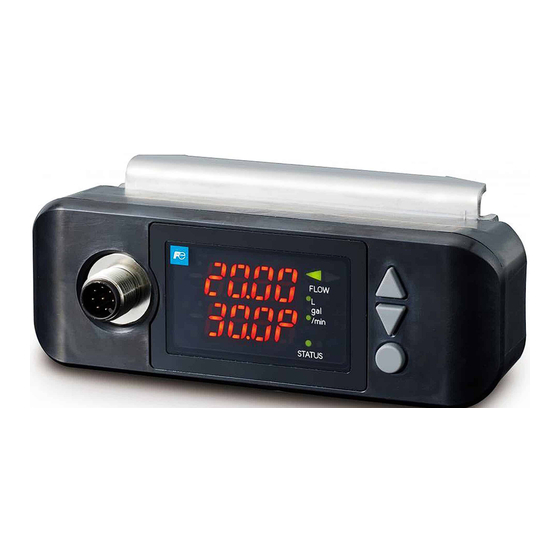
1.4. Name and function of each part 1.4.1. Flowmeter unit (FSZ) Name Description Dedicated cable This is a wire connection port for the power supply, current output, and connector connection port contact output. LED display unit It displays the flow rate and settings. -
Page 11: Installation
2. INSTALLATION Select the mounting location in consideration of the following items from the viewpoint of ease of maintenance and inspection, and maintaining the life and reliability of the flowmeter. (1) Places where the ambient temperature and humidity are -15 to +60°C and 95% RH or less. (2) Indoor or outdoor locations where there is no exposure to direct sunlight or wind and rain. -
Page 12: Conditions On Straight Pipe
2.1.1. Conditions on straight pipe - 5 -... -
Page 13: Mounting Orientation
2.1.2. Mounting orientation The flowmeter can be mounted vertically, horizontally, or in any other position. The flow direction is configurable (see “3.8.1Piping parameter setting method”) and it can be mounted in a direction that makes the LED display more visible. Pay attention to the following when installing the flowmeter. -
Page 14: Installation
2.2. Installation ・Remove dirt and rust from the piping surface where the flowmeter will be mounted, as dirt and rust can cause measurement failure and measurement error. ・Be careful not to over-tighten the screws, as this may cause damage. ・To prevent damaging it, do not rotate it in the direction of the pipe circumference after tightening the screws. 2.2.1. -
Page 15: Wiring
2.3. Wiring 2.3.1. Caution in wiring (1) We recommend using a shielded cable to extend the length of the cable for the output signal. (2) To prevent noise intrusion, do not run the signal cable inside the same duct as that used for wires such as power lines. -
Page 16: Parameters
3. PARAMETERS 3.1. Description of display/setting unit The display/setting unit are shown below. 3.1.1. Display/setting unit Name Description display △ UP key Use to select items, numeric values, and symbols. Use to move the cursor. ▽ DOWN key Use to select items, numeric values, and symbols. Use to move the cursor. -
Page 17: Description Of Measurement Display
3.1.2. Description of measurement display ○ LED lamp: Displays measurement values and setting values (4-digit, 2-row, 7-segment display). “Measurement display” • Measurement display indicates 2 types of flow rates and 3 types of total values. Press the Entry key to switch the display. The data unit is displayed with up to 4 digits. •... -
Page 18: 7-Segment Display
3.1.3. 7-segment display 7-segment characters, numbers, and alphabetic characters used in the character display of the unit are supported. Number and 7-segment character support Alphabetic character and 7-segment support - 11 -... -
Page 19: Composition Of Key Operation
3.2. Composition of key operation - 12 -... - Page 20 - 13 -...
- Page 21 - 14 -...
- Page 22 - 15 -...
-
Page 23: Parameter Initial Value List
3.3. Parameter initial value list These are factory default settings. Setting item/7-segment display Initial value Setting range 7-segment display 7-segment display (selection items) Key lock 0000 to 9999 Zero point adjustment No adjustment, clear, adjustment Instantaneous flow rate decimal place FSZ08 ***.* **.**,***.*,****... - Page 24 Setting item/7-segment display Initial value Setting range 7-segment display 7-segment display Piping outer diameter 5.00 to 99.99 [mm] FSZ08 FSZ15 FSZ25 Piping material Carbon steel, stainless steel, copper, PVC, PFA, PTFE Pipe thickness FSZ08 0.10 to 9.99 [mm] FSZ15 FSZ25 Kind of fluid Water, seawater, 1500 Fluid sound velocity...
-
Page 25: Setting When The Power Is Turned On For The First
Carbon Steel, stainless steel (factory default), copper, PVC, PFA, PTFE 3. Pipe thickness 0.10 to 9.99 [mm] (factory default: FSZ 08: 2.00, FSZ 15: 2.50, FSZ 25: 3.00 [mm]) 4. Measurement fluids : Water (factory default), seawater, fluid sound velocity Fluid sound velocity: (Sound velocity: 1000 to 2000 [m/s]) For specific key operations, refer to the typical operation indicated below. -
Page 26: Measurement Display Setting
3.5. Measurement display setting Description ● The measurement display indicates 2 types of flow rates and 3 types of total values. ● Flow display 1 Row 1: Instantaneous flow value, Row 2: Instantaneous flow rate % value You can set the decimal place position of the instantaneous flow rate value for the first row. ●... -
Page 27: Parameter Protection (Protect)
3.6. Parameter protection (protect) Description ● You can protect parameters to prevent accidental changes to the flowmeter settings. ● You can lock the unprotected parameters by setting the “ID code” (Note) in the system settings. ● You can unlock the protected parameters by setting the “ID code” (Note) in the system settings. ●... -
Page 28: Zero Point Adjustment
3.7. Zero point adjustment Description ● Calibrates the zero point. No adjustment : Does not adjust the zero point. “ ” Clear : Sets the zero point calibration value to “0”. “ ” Use it when zero point calibration cannot be performed after stopping the flow. Note 1) Stop the flow as much as possible and perform “ADJ”... -
Page 29: Measurement Settings
: Carbon Steel, stainless steel (factory default), copper, PVC, PFA, PTFE 3. Pipe thickness : 0.10 to 9.99 [mm] (factory default: FSZ 08: 2.00, FSZ 15: 2.50, FSZ 25: 3.00 [mm]) 4. Measurement fluids : Water (factory default), seawater, fluid sound velocity Fluid sound velocity: (Sound velocity: 1000 to 2000 [m/s]) 5. - Page 30 Fluid speed velocity: 1000 to 2000 [m/s] Press the △▽ keys to set the values. Press the ○ key to go to Display 8. ○ key Dynamic viscosity coefficient: 0.001 to 999.9 × 10⁻⁶ [m Press the △▽ keys to set the values. Press the ○...
-
Page 31: Range Setting
3.9. Range setting 3.9.1. Damping Description ● Used to reduce fluctuation of measured values. The setting value is a time constant. (Response time of about 63%.) Setting range: 0 sec, 1 sec, 3 sec, 5 sec, 10 sec, 30 sec, 60 sec, 90 sec Note) When the damping setting is set to 0 seconds, the response time is as follows. -
Page 32: Range Setting
3.9.5. Range setting Description ● Sets the range value (full scale value) for the flow rate being measured. * The analog output (4 to 20 mA) corresponds to the range setting. ● Setting range: FSZ08: 0.00 to 99.99 [L/min], (Factory default 15.00 [L/min]) FSZ15: 0.0 to 999.9 [L/min], (Factory default 50.0 [L/min]) FSZ25: 0.0 to 999.9 [L/min], (Factory default 150.0 [L/min]) * The lower limit of output is -20% (0.8 mA). - Page 33 Output calibration span: 0.0 to 200.0 [%] Press the △▽ keys to set the values. Press the ○ key to go to Display 8. ○ Key Full scale: FSZ08: 0.00 to 99.99, FSZ15: 0.0 to 999.9, FSZ25: 0.0 to 999.9 [L/min] Press the △▽...
-
Page 34: Status Settings
3.10. Status settings 3.10.1. DO output settings Description ● Selects the total pulse and status (warning and flow rate switch, total switch, etc.) output. ● DO output types (common to DO1 and DO2): Settable range Not used : Does not use the contact output. All alarm : Contact output is activated upon instances of device error or process error Device error... -
Page 35: Total Flow Pulse Setting
3.10.2. Total flow pulse setting (total rate, pulse width) Description ● When totaling the flow rate into the integrator, set the output pulse as follows. ● Total rate: Total rate (volume) per pulse. When the total volume reaches the amount set by the total flow rate, one total flow pulse is output. Setting range: FSZ08: 0.1, 1, 10, 100, 1000 [L] (Factory default: 10 [L]) FSZ15: 0.1, 1, 10, 100, 1000 [L] (Factory default 10 [L]) FSZ25: 1, 10, 100, 1000, 10000 [L] (Factory default 100 [L]) -
Page 36: Key Operations For Status Settings
3.10.4. Key operations for status settings Operation (example) Display and keystrokes Description Press and hold the ○ key to go to Display 2. Measurement display Press and hold the ○ key Press the ▽ key once and select “SET DO”. Press the ○... -
Page 37: System Settings
3.11. System settings 3.11.1. ON/OFF setting of measurement display Description ● This function turns the LED display ON and OFF. ● Even when set to OFF, the diagnostic indicator lamp STATUS and the flow direction FLOW LED will still be ON. Settings LED display ON/OFF: The “ON”... -
Page 38: Key Operations For System Settings
3.11.4. Key operations for system settings Operation (example) Display and keystrokes Description Press and hold the ○ key to go to Display 2. Measurement display Press and hold the ○ key Press the ▽ key three times and select “SET SYS”. Press the ○... - Page 39 Press the ○ key to return to the measurement display. ○ Key Measurement display - 32 -...
-
Page 40: Maintenance
3.12. Maintenance 3.12.1. Calibration and verification of analog output Description ● Current calibration mode Calibrates the analog signal (4 to 20 mA DC) so that the output is 4 mA at 0% and 20 mA at 100%. Select 4 mA and 20 mA in the current calibration mode, and adjust it by pressing the △ (UP) key or ▽ (DOWN) key. ●... -
Page 41: Checking The Status Output And Total Pulse
3.12.2. Checking the status output and total pulse operation Description ● Status simulated output (DO1, DO2) This function checks the status output. Setting ON: Sets the contact to short-circuit. OFF: Opens the contact. ● Total pulse simulated output (DO1 only) This function checks the total pulse output. -
Page 42: How To Set The Test Mode
3.12.3. How to set the test mode (flow simulated output) Description ● This function sets simulated output for the volume flow rate and checks each output (LED display, analog output, DO output). The output at the time of setting is set as the initial value, changes according to the time of the set “tracking time”... - Page 43 Press the ○ key to return to the measurement display. ○ Key The LED on the first row will blink “TEST” and the output will change. After the set follow-up time elapses, the output will become the simulated flow target value and Measurement display stabilize.
-
Page 44: Maintenance And Inspection
4. MAINTENANCE AND INSPECTION 4.1. Daily check Check the following items externally and visually. • Is the mounting bracket loose? => Tighten it to the recommended tightening torque. • Is there any abnormality in the receipt wave (STATUS is red)? => Check “4.3.2 Error and countermeasures when an alarm is displayed”. -
Page 45: Error And Countermeasures When An Alarm Is
4.3.2. Error and countermeasures when an alarm is displayed Diagnostic LED lamp Condition Countermeasure indicator Second row lamp STATUS ● E1-1 Backup memory error • Turn the power ON again (OFF, ON). If it is not restored, (Red lamp) the backup memory will fail. =>... -
Page 46: Diagnosis When There Is No Receipt Wave Or It Is Weak Or The Receipt Wave Is
4.3.2.1. Diagnosis when there is no receipt wave or it is weak or the receipt wave is abnormal When there is no receipt wave or it is weak or the receipt wave shape is abnormal, it is likely that there are incorrect pipe parameter settings, incomplete installation, fluid and pipe problems, and/or flowmeter failures. -
Page 47: Measured Value Error
4.3.3. Measured value error Condition Cause Countermeasure That is actually how it flows. The measured value is Change the flow direction setting. displayed as “-” (minus). (Refer to “3.8.1Piping parameter setting method”) Abnormal fluctuation in Straight pipe is not long enough Move to a location where you can secure measured values... -
Page 48: Analog Output Errors
4.3.4. Analog output errors Condition Cause Countermeasure ● Set the correct range setting. The current output is not The range setting is not correct. correct. ● Calibrate the analog output. When the display is 0, it The analog output is out of alignment. will not reach 4 mA. -
Page 49: Appendix
5. APPENDIX 5.1. Specification - 42 -... - Page 50 - 43 -...
-
Page 51: Outline Diagram
5.2. Outline diagram 1. Flowmeter Type: FSZ08 Type: FSZ15 Type: FSZ25 2. Dedicated cable - 44 -... -
Page 52: Pipe Data
5.3. Pipe data Carbon steel pipe SGP for piping applications (JIS G3452-2014) *1: The setting for the pipe material is carbon steel SGP. Pipe designation Outer diameter Thickness (mm) (mm) 13.8 17.3 21.7 27.2 34.0 1 1/4 42.7 Carbon steel pipe for pressure service STPG (JIS G3454-2017) Nominal thickness JIS pipe size Outer diameter... - Page 53 Polyethylene pipe for waterworks applications (JIS K6762-2004) *3: The setting for the pipe material is PVC. Type 1 (flexible pipe) Type 2 (rigid pipe) Nominal diameter Outer diameter Thickness Weight Thickness Weight (mm) (mm) (mm) (kg/m) (mm) (kg/m) 21.5 0.184 0.143 27.0 0.269...
- Page 54 (a) Sound velocity with temperature change in water (0 to 100°C) T°C V m/s T°C V m/s T°C V m/s T°C V m/s 1402.74 1407.71 1499.64 1543.93 1555.40 1412.57 1502.20 1544.95 1555.31 1417.32 1504.68 1545.92 1555.18 1421.98 1507.10 1546.83 1555.02 1426.50 1509.44 1547.70...
- Page 55 (c) Dynamic viscosity coefficient of various fluids ρg/cm ν (×10 Fluid name T°C V m/s Acetone 0.7905 1190 0.407 Aniline 1.0216 1659 1.762 Ether 0.7135 1006 0.336 Ethylene glycol 1.1131 1666 21.112 Chloroform 1.4870 1001 0.383 Glycerol 1.2613 1923 11.885 Acetic acid 1.0495 1159...
-
Page 56: Emc Conformity
5.4. EMC CONFORMITY EMC CONFORMITY: EMC Directive(2014/30/EU) Emission measurements: EN IEC 61326-2-3:2021 and EN IEC 61326-1:2021 Requirements Standard and limits Radiated emission EN 55011:2016+A1:2017+A11:2020+A2:2021 Group 1, Class A Immunity tests: EN IEC 61326-2-3:2021 and EN IEC 61326-1:2021 Requirements Basic EMC standard or test method Electrostatic discharge EN 61000-4-2:2009 Radiated, radio-frequency, electromagnetic field...
Need help?
Do you have a question about the FSZ and is the answer not in the manual?
Questions and answers