
Related Manuals for Fuji Electric FLV


Summary of Contents for Fuji Electric FLV
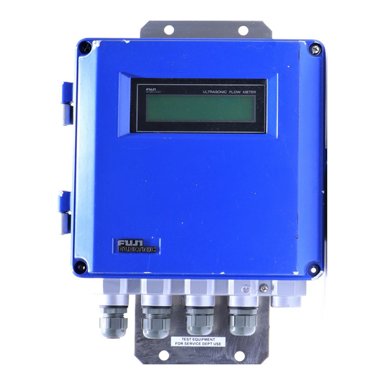
- Page 1 Instruction Manual ULTRASONIC FLOWMETER TYPE: INF-TN2FLVa-E Fuji Electric Co.,Ltd.
-
Page 2: Preface
• Modification of this flowmeter is strictly prohibited unless a written approval is obtained from the manufacturer. Fuji Electric will not bear any responsibility for a trouble caused by such a modification. • This instruction manual shall be stored by the person who actually uses the flowmeter. - Page 3 Flow Meter Power Supply AC100–240V 50/60Hz Type DC20–30V Ser. No. Mfd. Fuji Electric Co.,Ltd. Fuji Electric Co., Ltd. Made in Japan Converter Large type sensor Ultrasonic Flow Meter Type. Ser. No. Mfd. T K 7 7 3 7 9 2 Fuji Electric Co.,Ltd.
-
Page 4: Caution On Safety
CAUTION ON SAFETY • The cautionary descriptions listed here contain important information about safety, so they should always be observed. Those safety precautions are ranked 2 levels; DANGER and CAUTION. Wrong handling may cause a dangerous situation, in which DANGER there is a risk of death or heavy injury. -
Page 5: Table Of Contents
CONTENTS PREFACE ............................i CAUTION ON SAFETY ....................... v CONTENTS ..........................vii OPERATING PARTS AND THEIR FUNCTIONS ............... 1 MOUNTING OF CONVERTER .................... 2 Selection of mounting place ....................... 2 Mounting method ........................2 Outline diagram (unit: in.) ......................3 WIRING OF THE CONVERTER .................. - Page 6 5.4 (17) Selection of language (English/Japanese) ..............30 5.4 (18) Analog output check ....................31 5.4 (19) Analog output calibration .................... 32 5.4 (20) Status output check ...................... 33 5.4 (21) Test mode ........................34 MAINTENANCE AND INSPECTION ................35 Maintenance ..........................
-
Page 7: Operating Parts And Their Functions
1. OPERATING PARTS AND THEIR FUNCTIONS The names and funcitons of parts of the converter are as follows. Names of parts of converter ULTRASONIC FLOW METER PIPE OUTPUT DAMP ZERO FUNK FLOW SW TOTAL CUT OFF DISP STATUS SYSTEM CHECK ENTER TR-out1 TR-out2... -
Page 8: Mounting Of Converter
2. MOUNTING OF CONVERTER 2.1 Selection of mounting place Install the converter at a place satisfying the following conditions. 1. Ambient temperature does not exceed a range of +14°F to +140°F. When installing outdoors, attach a shade or put the converter in an outdoor panel to protect it from direct sunlight. -
Page 9: Outline Diagram (Unit: In.)
Name plate 1/8" 3.75" .55" 9.06" Frame end 3.15" Ground terminal 2.36" 1.57" 1.57" 1.57" 1.57" Chain & spring Converter FLV Sensor FLW1 (small type sensor) Saddle Scale (inch) Scale (mm) BNC connector 4.49" 3.66" Locking unit Sensor unit Element holder... -
Page 10: Wiring Of The Converter
1. For signal cable between the sensor and converter, use double-shielded coaxial cables specified by Fuji Electric. The coaxial cable should be refrained from connecting midway. 2. The signal cable between the sensor and converter should be run in metalic conduits. -
Page 11: Wiring To Terminals
3.4 Wiring to terminals Cables should be connected as shown in the following diagrams. AC power DC power AC power terminal DC power terminal ULTRASONIC FLOW METER PIPE OUTPUT DAMP ZERO FUNK FLOW SW TOTAL CUT OFF DISP STATUS SYSTEM CHECK ENTER 100 to 240V AC... -
Page 12: Operation And Works
4. OPERATION AND WORKS 4.1 Before operation Check the following before starting operation. Power Power check See Item 4.2 (1) Wiring 1) Check of main board terminal block 2) Check of power board terminal block See Item 3.4 3) Check of grounding terminal Piping 1) Check that a piping is filled with fluid. -
Page 13: Power On And Status
4.2 Power ON and status Power specification AC power Use power supply of 100 to 240VAC ±10% (50/60 Hz). DC power A power of 20V to 30V DC is available. Power ON When the instrument is turned on, the following data are displayed on the LCD after making a self-check of the devices. -
Page 14: Setting Of Parameters
5. SETTING OF PARAMETERS 5.1 Outline of operating procedures Proceed to the following procedure before starting measurements. Installation and wiring Chapter 3 of converter Chapter 4 Power ON Input of piping Check of piping 5.4 (1) 5.4 (1) specification specification Chapter 8 Installation of sensor Measurement error... -
Page 15: Description Of Key Operation
5.2 Description of key operation Note) When adjustment is performed or setting is changed in this Chapter, be sure to enter parameters in the list attached to the converter. Pressing the FUNC key enables you to perform the functions shown on the upper side of the ten-keys. - Page 16 Description of key (2/2) Name Key display Description By pressing this key, the circumstance of pipe, which has been entered, is converted into the outside diameter. (valid only when setting the outside diameter of pipe) PIPE (Pipe) FUNC PIPE To enter the size and material of the sensor piping. OUTPUT FUNC To set the condition of an analog output...
-
Page 17: List Of Setting Items
5.3 List of setting items Measurement screen Piping specifications ----------------------------------- See Item 5.4 (1) ( FUNC PIPE ) Setting of output Range ------------------------ See Item 5.4 (2) ( FUNC OUTPUT ) Output limit ----------------- See Item 5.4 (3) Burn-out--------------------- See Item 5.4 (4) Damping ------------------------------------------------- See Item 5.4 (5) ( FUNC DAMP ) Zero adjustment ---------------------------------------- See Item 5.4 (6) -
Page 18: Setting Of Parameters
5.4 Setting of parameters • Units are displayed in metric system. 5.4 (1) Setting of piping specifications Description Set the data of pipe required for measurement. The mounting dimension of the sensor is automatically calculated. Data of each item should be entered according to the display. Item Entry Range or menu... - Page 19 Operation (example) Outside diameter:114.3mm, pipe material:carbon steel, thickness:4.5mm, lining material:mortar, thickness:1.25mm, fluid:heavy water, sound velocity: 1388m/s, dynamic viscosity coefficient: 1.129 x 10 /s, sensor mounting method:V method, type: FLW12, Transmission voltage:8 times Key operation Description Display FUNC PIPE The sensor mounting dimension is SENSOR SPACING displayed.
-
Page 20: 2) Setting Of Analog Output Range
5.4 (2) Setting of analog output range Description An analog output range is set to provide an output of 4 to 20mA in the specified range of measured values (flow rate or flow velocity). [Measurement items] Selection of range unit .... m/s Choose any of Note 1) l/s, l/m l/h, Ml/d... - Page 21 Operation (example) When setting the base scale to 0m /h, full scale 1 to 100m /h, full scale 2 to – 100m /h and hysteresis to 5% in the forward/reverse range. Key operation Description Display FUNC OUTPUT Select “m3/h”. , ENTER RANGE UNIT m3/h RANGE TYPE...
-
Page 22: 3) Setting Of Analog Output Limit
5.4 (3) Setting of analog output limit Description Set the high/low limits within the range of analog output of 0.8 to 23.2mA (-20 to 120%). Analog output High limit 23.2mA 20mA Low limit Flow rate -20% 0% 100% 120% 0.8mA Operation (example) Low limit : -10% (2.4mA), high limit : 110% (21.6mA) Key operation Description... -
Page 23: 4) Setting Of Burn-Out
5.4 (4) Setting of burn-out Description When the pipe is empty of fluid or when air bubbles are contained in fluid, the flow rate can not be measured correctly. In such a case, the analog output needs to be set to “HOLD”, “HIGH”... -
Page 24: 5) Setting Of Damping
5.4 (5) Setting of damping Description Damping is used to suppress fluctuation of measured values. The set value is a time constant (about 63% response time). (Setting range : 0 to 100 sec) Time Response time Unless otherwise specified in the order sheet, the setting time of damping is adjusted to 5 sec. Operation (example) Change of set value to 20 sec. -
Page 25: 6) Zero Adjustment
5.4 (6) Zero adjustment Description Zero point of measured value is adjusted. (Setting items) • ZERO POINT ADJUST : Stop the flow of fluid and adjust zero point. The zero pont is the state of measurement at set point. • ZERO POINT CLEAR : This setting is used when fluid will not stop flowing. -
Page 26: 7) Setting Of Measurement Display Specifications
5.4 (7) Setting of measurement display specifications Description Select measured value from the following. 1. Setting of measurement display 1st line Select any one from the following 7 types for the 1st line display. F : TOTAL : Forward integral value R : TOTAL : Reverse integral value TOTAL DIFF... -
Page 27: 8) Low Flow Output Cut
Operation (example) Display instantaneous flow velocity and instantaneous flow unit in m3/h, and instantanous flow rate in 3 digits after decimal point. Key operation Description Display FUNC DISP 1: DISPLAY KIND , ENTER Select “Flow velocity”. VELOCITY , ENTER Select :m /h”. -
Page 28: 9) Setting Of Integrated Output Unit And Constant
5.4 (9) Setting of integrated output unit and constant Description Integrated output unit is set to integrate measurement value (flow rate) Just after setting of measured value is completed, the pulse counter begins integration by clearing the previous integrated value. 1. -
Page 29: 10) Setting Of Integral Preset Value
5.4 (10) Setting of integral preset value Description Set integrated preset value F: TOTAL PRESET: Forward integral preset value R: TOTAL PRESET: Reverse integral preset value Setting range: 0 to 9999999 Addition Preset value Time Note: In case of setting, please keep “TOTAL MODE” suspended. Operation (example) Forward direction : 1000m , reverse direction : 2000m Key operation... -
Page 30: 11) Setting Of Integration Switch
5.4 (11) Setting of integration switch Description When an integral value exceeds the set value, the status output is provided. F: TOTAL SW: Forward integration switch R: TOTAL SW: Reverse integration switch Setting range: 0 to 9999999 Note) When setting the status output, integration switch is valid only when “F: TOTAL SW”... -
Page 31: 12) Selection Of Integral Pulse Output Pulse Width
5.4 (12) Selection of integral pulse output pulse width Description The following 2 types can be selected according to the counter connected. When setting status output, set the pulse width to use “F:TOTAL” or “R:TOTAL”. • 50msec • 100msec Note: In case of setting, please keep “TOTAL MODE” suspended. Operation (example) Pulse width: 100msec. -
Page 32: 13) Setting Of Measured Value High And Low Limit Switch
5.4 (13) Setting of measured value high and low limit switch Description 1. Set high limit and low limit of switching point when using high limit flow or low limit flow to set the status output. Setting range : 0 to ±105 ft./s of flow velocity [Relation between status output and set value] •... -
Page 33: 14) Setting Of Status Output
5.4 (14) Setting of status output Description • When the status of setting or integral pulse is outputted, the contents of output is set. NOT USED : No output SIGNAL ERROR : ON at abnormal measurement F: TOTAL PULSE : Forward flow integral pulse R: TOTAL PULSE : Reverse flow integral pulse FLOW SW HIGH... -
Page 34: 15) Calibration Of Measured Value
Operation (example) When setting the forward integral pulse and contact output in the normal mode. Key operation Description Display STATUS CHANEL , ENTER Select “CHANNEL 2”. CHANNEL 2 , ENTER Select “F: TOTAL ALARM”. STATUS SEL : F : TOTAL ALARM , ENTER Select “SPOT”. -
Page 35: 16) Switch Of Measurement Unit System
5.4 (16) Switch of measurement unit system Description Measurement units can be set in the two systems, metric system and inch system. (Setting contents) • Metric system Pipe dimension ------------ mm Flow velocity unit --------- m/s Flow rate unit -------------- l/s, l/m l/h Ml/d /s, m /m, m /h, Mm... -
Page 36: 17) Selection Of Language (English/Japanese)
5.4 (17) Selection of language (English/Japanese) Description 2 kinds of language, English and Japanese (Katakana) can be selected on this display, at the time of setting. Operation (example) Selection of English display Key operation Description Display FUNC SYSTEM LANGUAGE Select “Language”. JAPANESE LANGUAGE Select “English”. -
Page 37: 18) Analog Output Check
5.4 (18) Analog output check Description Check the analog output circuit. Check to make sure that the output values at -20% to 120% are 0.8mA to 23.2mA. Connect an ammeter to the Iout terminal as shown below. Iout TRout 1 Ammeter Operation (example) Check of analog output of 4mA, 8mA, 12mA, 16mA, 20mA Key operation... -
Page 38: 19) Analog Output Calibration
5.4 (19) Analog output calibration Description The analog output circuit is calibrated so that the measured flow rate is set to provide an output of 4mA in the base scale and 20mA in the full scale. Calibration should be performed by connecting an ammeter to Iout terminal as shown below. Iout TRout 1 Ammeter... -
Page 39: 20) Status Output Check
5.4 (20) Status output check Description Perform check of status output for ON-OFF operation. Status output is an open collector. A check is performed by connecting a voltmeter to terminals, TRout 1 and TRout 2 as shown below. TR out 1 TR out 2 Signal receiving instrument Volt meter... -
Page 40: 21) Test Mode
5.4 (21) Test mode Description The test mode is used to check for integrated conditions and action of the flow switch, etc. by entering measuring flow rate simulately. With base scale set to 0% and full scale to 100%, an arrival time from previous value to target value can be set as shown below: Data setting range: 0 to ±120% Tracking time setting range: 0 to 900sec... -
Page 41: Maintenance And Inspection
6. MAINTENANCE AND INSPECTION 6.1 Maintenance (1) LCD display unit Expected service life of LCD is 7 years. It is recommended that LCD should be replaced with new one in about 5 years since it is put into operation, or it may offer deteriorated contrast. [Replacement procedure] Power OFF Remove the connector from the key panel and replace the LCD display unit (see parts list). -
Page 42: Troubleshooting
O, I normal inside pipe. doesn't appear Backup error Forward flow of fluid indication Reverse flow of fluid — 7.1 (2) LCD indication when power turned ON In case of no indication System abnormal (CPU stopped) Contact Fuji Electric. -
Page 43: 3) Detail Check For Abnormal Status
7.1 (3) Detail check for abnormal status Description Status display at the upper right of the measurement screen is detailed as follows: (Status display) (Contents of display) (Detailed Contents) NORMAL CAL. ERROR • Check for piping input data. • Turn ON/OFF the power. RECEIVED SIGNAL ERROR •... -
Page 44: Faults And Remedies
7.2 Faults and remedies 7.2 (1) LCD display abnormal Status Cause • Power is not turned ON. • Power voltage is low. No indication • Fuse is burnout. appears. • LCD is abnormal. Take remedy in “7.2 (5) Remedy for hardware fault”... -
Page 45: 3) Measured Value Abnormal
7.2 (3) Measured value abnormal Remedy Cause Status • Connection between transmitter Minus (-) symbol and sensor is reversed. Connect correctly. indicated on mea- (Upstream and down stream sured value detectors should be connected reversely) • Flow of fluid is reversed. Measured value •... - Page 46 Remedy Status Cause (Continued) Turbidity is high. Turbidity is higher than inflow water contamination or return • Change sensor sludge. mounting from V method to Z method. Scale deposits on the inside of • Move sensor to a old pipe place of smaller Thick lining diameter on the...
- Page 47 Remedy Status Cause Error in measured • Input piping specifications Error of about 3% value differ from the actual ones. occurs when inner diameter differs by • Scale deposits on old pipe • Input the correct specifications • Input scale as a lining.
-
Page 48: 4) Analog Output Abnormal
7.2 (5) Remedy for hardware fault When hardware is in trouble after following “6. Maintenance and inspection” and “7. Troubleshooting”, details of trouble and self-check should be notified to Fuji Electric. -
Page 49: Mounting Method
8. MOUNTING METHOD 8.1 Mounting of sensor 8.1 (1) Mounting procedure of sensor Mount the sensor on the pipe, and perform the following works in order before making measurement. 8.1 (2) Selection of mounting place 8.1 (3) Selection of mounting method Processor of sensor 8.1 (4) mounting surface... -
Page 50: 2) Selection Of Mounting Place
8.1 (2) Selection of mounting place Mounting place for the sensor, i. e. conditions of piping where flow rate is measured, has consider- able influence on measurement accuracy. A place satisfying the following conditions should be selected. A place where there is a straight pipe portion of 10D or more on upstream side and of 5D or more on the downstream side. -
Page 51: 3) Selection Of Mounting Method
8.1 (3) Selection of mounting method There are two ways for mounting the sensor, the V method and the Z method (See Fig. 8-2). Approx. D Approx. D/2 Sensor Sensor V method Z method Fig. 8-2 Mounting method The Z method should be used in the following cases. •... -
Page 52: 5) Determination Of Mounting Position (With Z Method For Large And Small Types)
8.1 (5) Determination of mounting position (with Z method for large and small types) Carry out the following to determine the mounting position. Gauge paper is necessary for this work. (Refer to Appendix 1. “How to make gauge paper”.) 4 in. Align the edge of gauge paper with a point about 4 in. -
Page 53: 6) Cable End Treatment
8.1 (6) Cable end treatment The end of coaxial cable is treated at the factory prior to delivery. If the cable needs to be cut before use, the conductor and the shielding wires should be treated using clamp terminals. Conductor (white, +) Shielding wire (black, G) Clamp terminal Outer shielding wire (green) -
Page 54: 7) Connection Of Cable To Small Type Sensor
8.1 (7) Connection of cable to small type sensor 1. Loosen the earth screw and the retaining knob on 4. Secure the coaxial cable with the cable clamp. the sensor using a screwdriver, then remove the cover from the sensor. Cover Cable clamp Loosen... -
Page 55: 8) Mounting Of Small Type Sensor On Pipe
8.1 (8) Mounting of small type sensor on pipe The small type sensor is mounted on pipe with a diameter of ø50 to 250 (V method) or ø150 to 400 (Z method) for measurements. 1. Mounting of sensor (V method) Mounting the sensor using the following procedure. - Page 56 2. Mounting of sensor (Z method) Mounting the sensor using the following procedure 1. Spread silicone filler over the whole transmitting 3. Make sure that the center mark on the sensor is side of the sensor. Care should be taken to aligned with the marking line.
-
Page 57: 9) Assembling Procedure Of The Sensor
8.1 (9) Assembling procedure of the sensor When the small type sensor (FLW1) is shipped with cables of more than 32.8 ft. in length, it is delivered, disassembled since cable weight is applied to the stand or piping of the sensor during shipment. -
Page 58: 10) Connection Of Cable To Large Type Sensor
8.1 (10) Connection of cable to large type sensor 1. Slightly move the sensor cover and remove it 3. Connect the coaxial cable to the terminals (G, +) using an screwdriver or the like. and secure the cable with the cable clamp. Cover Cable retain Transmitting... -
Page 59: 11) Mounting Of Large Type Sensor On Pipe
8.1 (11) Mounting of large type sensor on pipe 1. Adjustment of guide plate height 3. Mounting of sensor Attach the sensor to the pipe. Make sure that it is • Clean the sensor transmitting surface and pipe parallel with the pipe shaft. mounting surface. -
Page 60: 12) Mounting Of High Temperature Sensor On Pipe
8.1 (12) Mounting of high temperature sensor on pipe 1. By loosening lock nuts, slide the sensor to fit the 3. Mount the sensor saddles on the pipe with stain- mounting size displayed on the converter. less belt. Tighten the lock nuts. Stainless belt Locking nut BN connector... -
Page 61: Appendix 1. Specifications
3.3 ft./s 3.26 to 105 ft./s 1.0% of rate ø12 to ø236 in. 0 to 3.26 ft./s 0.03 ft./s Converter (Type : FLV) • Measuring method : Propagation delay time system : 100 to 240V ±10% AC, 50/60Hz • Power supply •... - Page 62 Sensor (Type : FLW) • Mounting method : Pipe-mounting • Mounting method of sensor: V method or Z method • Attaching belt/wire : Small type sensor: stainless chain Large type sensor: stainless wire High temperature sensor: stainless belt • Sound coupler : Silicon rubber •...
- Page 63 (2) Function • Display language : Japanese (Katakana)/English selectable • Instantaneous value display function :Flow velocity/flow rate (with flow direction) selection Unit : metric system/inch system selectable Metric system English sytem Flow velocity ft/s Flow rate l/s, l/m, l/h, Ml/d gal/s, gal/m, gal/h, Mgal/d /s, m /m, m...
- Page 64 (4) Mounting of sensor Plastic wedge Ultrasonic oscillator Pipe Lining (5) Construction (1) Single-measuring-path system (V method) Cable Sensor 4 to 20mA Contact Converter (2) Single-measuring-path system (Z method) Cable Sensor 4 to 20mA Contact Converter...
-
Page 65: Appendix 2. How To Make Gauge Paper
APPENDIX 2. HOW TO MAKE GAUGE PAPER Prepare a rectangular sheet of paper (or vinyl sheet) with its length of more than 4D and width of 8 in. (D, if possible). D : Pipe diameter 4D or more ® Parallel Draw a line perpendicular to the long side at a point about 4 in. -
Page 66: Appendix 3. Composition Of Key Operation
APPENDIX 3. COMPOSITION OF KEY OPERATION (1) SETTING OF MEASURE DISPLAY FUNC DISP [Initial value] [Velocity] 1 : DISPLAY KIND VELOCITY RANGE % TOTAL FORWARD TOTAL REVERSE TOTAL DIFF. F : TOTAL PULSE R : TOTAL PULSE 2 : FLOW UNIT gal/s [m3/s] gal/m... - Page 67 (2) SETTING OF PIPING SPECIFICATIONS FUNC PIPE SENSOR SPACING [13 mm] OUTER DIAMETER (13 to 6100 mm) [Entry of dimension of outer circumstance] [0.52 inch] Press "/p" key. Converted into (0.52 to 240 inch) outer diameter PIPE MATERIAL CARBON STEEL [Carbon steel] STAINLESS STEEL COPPER...
- Page 68 SETTING OF FLOW SWITCH FUNC FLOW SW (0 to ±32 m/s) FLOW SW LOW [0 m/s] (0 to ±105 ft/s) [0 ft/s] (0 to ±32 m/s) FLOW SW HIGH [32 m/s] (0 to ±105 ft/s) [105 ft/s] (0 to 20%) [10 %] FLOW SW HYS.
- Page 69 (6) SETTING OF LOW FLOW OUTPUT CUT FUNC CUT OFF CUT OFF (0 to 5 m/s) [0 m/s] (0 to 16.4 ft/s) [0 ft/s] (7) SETTING OF TOTAL OUTPUT FUNC TOTAL [TOTAL STOP] TOTAL MODE TOTAL STOP TOTAL RUN TOTAL RESET TOTAL UNIT [m3] kgal...
- Page 70 (10) SETTING OF SYSTEM CONDITION FUNC SYSTEM SYSTEM OF UNIT METRIC [METRIC] ENGLISH ENGLISH LANGUAGE [ENGLISH] JAPANESE OUTPUT CHECK (-20 to 120 %) [0 %] OUTPUT ADJUST SKIP SETTING 4 mA [4mA] 20 mA CHANNEL 1 STATUS CHECK [OFF] CHANNEL 2 [OFF] TEST MODE NOT USED...
- Page 71 (11) SELECTING OF STATUS FUNC STATUS STATUS CHANNEL CHANNEL 1 STATUS SEL.:CH1 NOT USED [NOT USED] SIGNAL ERROR F : TOTAL PULSE R : TOTAL PULSE FLOW SW HIGH FLOW SW LOW F : TOTAL ALARM R : TOTAL ALARM F : TOTAL OVERFLOW R : TOTAL OVERFLOW FULL SCALE2...
- Page 72 (12) ERROR CHECK FUNC CHECK R : NORMAL C : CAL. ERROR CHECK PIPE DATA POWER OFF ® ON H : RECEIVED CHECK BUBBLES IN PIPE SIGNAL ERROR CHECK PARTICLES IN PIPE W : WINDOW ERROR CHECK PIPE DATA O : RECEIVED CHANGE MOUNTING METHOD SIGNAL OVERFLOW I : NO RECEIVED...
-
Page 73: Appendix 4. Piping Data
APPENDIX 4. PIPING DATA Stainless steel pipe for pipe arrangement (JIS G3459-1988) Normal thickness Nominal Outer diameter Schedule Schedule Schedule Schedule Schedule Schedule Schedule (in.) diameter (in.) Thickness Thickness Thickness Thickness Thickness Thickness Thickness (in.) (in.) (in.) (in.) (in.) (in.) (in.) —... - Page 74 Asbestos cement pipe for city water (JIS A5301-1971) 1st type 4th type 2nd type 3rd type Nominal Thickness Outer diameter Thickness Outer diameter Thickness Outer diameter Thickness Outer diameter diameter of connected of connected of connected of connected of connected of connected of connected of connected...
- Page 75 Carbon steel pipe for pipe arrangement Vertical type cast iron pipe (JISG5521) (JIS G3452-1988) Thickness Nominal pipe Actual outer Outer diameter Thickness Nominal pipe diameter (in.) (in.) Normal pressure pipe Low pressure pipe — 3.66 1.07 — 4.65 1.34 6.65 1.68 8.66 1.91...
- Page 76 Steel pipe coated for city water STW (JIS G3443 1987) Kinds of symbol Kinds of symbol STW 41 STW 400 Nominal Outer STW 30 STW 38 Nominal thickness STW 290 STW 370 Nominal thickness diameter diameter Thickness Thickness Thickness Thickness Thickness Thickness Thickness...
- Page 77 Centrifugal nodular graphite cast iron pipe for city water (K type) (JWWA G-105 1971) Nominal diameter Thickness of pipe Actual outer diameter 1st type pipe 2nd type pipe 3rd type pipe 15.7 16.76 17.7 18.77 19.7 20.79 23.6 24.83 27.6 28.86 31.5 32.91...
- Page 78 Arc welded carbon steel pipe (JIS G3457-1976) Thickness Nominal diameter (in.) Outer diameter (in.) 13.8 14.00 2.04 2.17 2.40 2.67 15.7 16.00 2.33 2.48 2.63 3.06 17.7 18.00 2.63 2.80 3.10 3.44 19.7 20.00 2.93 3.12 3.45 3.83 4.21 4.60 21.7 22.00 3.22...
- Page 79 (a) Velocity of sound subject to change of temperature (b) Velocity of sound and density of various liquids in water (32 to 212°F) Name of liquid T°Fr oz./in. Vft./s T°F Vft./s T°F Vft./s T°F Vft./s T°F Vft./s Acetone 4600.99 0.4571 3903 Aniline 4617.29...
Need help?
Do you have a question about the FLV and is the answer not in the manual?
Questions and answers