Table of Contents
Advertisement
Quick Links
Advertisement
Table of Contents

Subscribe to Our Youtube Channel
Related Manuals for Fuji Electric FWD Series


Summary of Contents for Fuji Electric FWD Series
-
Page 2: Table Of Contents
TABLE OF CONTENTS Preface ............................... 2 Product Overview ..........................2 Safety Instructions ........................... 3 1. Introduction ..........................6 1-1. Scope of supply ......................6 1-2. Name of each part ......................6 2. Installation ..........................7 3. Setting Up ..........................12 3-1. ... -
Page 3: Preface
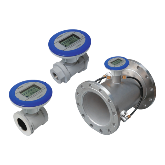
Preface Thank you very much for purchasing the Ultrasonic Flow Meter for Air FWD this time. Please be sure to read this Instruction Manual to use this product correctly and safely and to prevent failures. Please arrange for operators who actually use this product to know the context of this Instruction Manual surely. -
Page 4: Safety Instructions
Safety Instructions To ensure the safe use of this flow meter and to prevent a failure or an unexpected situation, instructions to which attention must be paid are indicated with the following symbols. Definitions Incorrect handling by failure to follow instructions with this sign may lead to imminent danger of death or serious injury. - Page 5 Operation This flow meter is not a specified measuring instrument defined in Japanese measurement law. The product cannot be used for billing transactions or certification. When opening a valve to start fluid flow, open the valve not all at once but Note gradually.
- Page 6 Wiring When performing wiring work, follow the instructions in this Manual. Use the product within the rating. Danger Do not use the product on a voltage exceeding permissible load. Do not place the product’s external connection cable together with or near to power supply line(s) or power line(s), etc.
-
Page 7: Introduction
Introduc ction 1. Scope e of supply Upon delive ery of the pr roduct, confi irm that the following ite ems are con tained in the e package: Name Q’ty Remarks Ultraso onic flowmete about usage. Cente ring collars Acces ssory of the wa afer connectio on type... -
Page 8: Installation
2. Installation It is recommended that Setting Up (Page12 onward) and changing Panel angle adjustment: (Page 11) are carried out before installation. This flowmeter can be installed both indoors and outdoors and on a horizontal pipe and a vertical pipe. ... - Page 9 Straight run requirements: Figure 2-1 Recommended straight pipe run (D: nominal diameter)
- Page 10 When the flow meter is installed near a pressure-reducing valve or a flow adjustment valve, strictly observe the “required straight run L” as shown in Figure 2-2, because ultrasonic noise may be generated inside the pipe. Note that when the flow meter is installed at the downstream of the pressure-reducing valve etc., there are many constraints.
- Page 11 afer conne ection type: Install th he flowmete r so that the e central axis s of the Figure 2-3 A Attaching c centering co ollars flow met ter is aligned d to that of p pipes to be connect ted.
- Page 12 Pane el angle ad djustment: The display y can be rot ated. It is re ecommended d to change the directio on before ins stallation. To change the e direction of f the display y section, tem mporarily loo osen a set s screw on the e neck part o the display...
-
Page 13: Setting Up
3. Setting Up It is recommended that the setting of the flow meter be carried out before installation. For this flow meter, 20 items shown in Table 3-1can be set. On delivery from factory, the “factory default settings” in Table 3-1 are arranged, so that the flow meter can be used as it is. Change the setting as necessary to make them suit to your working conditions. -
Page 14: Measurement And Indication Setting
Notes: 1. After resetting, "F9: Output pulse unit" will be set to 1000 [L], and “F14: Fluid selection” will be set to Air. 2. Qmin is the following value depending on the nominal diameter. 100A 150A 200A 10.0 24.0 40.0 Setting items include the one related to fluid to be applied, the ones related to measurement and indication, and the ones related to outputs. -
Page 15: Output Setting (For External Power Supply Type)
3-2. Output setting (for external power supply type) Output settings Unit of output pulse Output pulse unit F3 Alarm output Pulse output (reverse flow) Open drain output 2 Contact output Lower limit alarm Alarm output F6 Upper limit alarm F7 Alarm judgment value Instantaneous F2 flow‐rate Analog output FS flow‐rate F15 Current output Pressure Current output Temperature It is recommended that the setting of the flow meter be carried out before installation. Current output [F15] One of three output forms of instantaneous flow-rate, pressure and temperature can be selected for the current output to suit your usage. - Page 16 As a reference, Table 3-2 shows examples of conversion. Table 3-2 Flow rate conversion examples Pressure 0 (Atmospheric 0.98 (MPa) pressure) Temperature (C) 0.6(m FWD025 35(m 1.1(m FWD032 65(m 1.3(m FWD040 80(m 2.5(m FWD050 150(m 1180 1070 1600 1440 FWD065 240(m 1420 1280...
-
Page 17: Display
Display ure 4-1 Dis splay and bu uttons Back side of t he panel CK RIGHT BU UTTON [SW2] CK LEFT BUT TTON [SW1] CK CENTER BUTTON [SW CK RIGHT BU UTTON [SW2] CK LEFT BUTT TON [SW1] IN DISPLAY PPER COLUM PILOT LAMP B-DISPLAY... - Page 18 Notes: 1. “SW1+SW2” indicates that two switches are pressed simultaneously. 2. Indication cannot be changeover when the main display shows the instantaneous flow-rate [L/min]. 3. Accumulated flow volume (trip) is reset to zero in the following cases: When SW1+SW2 are pressed during the indication of accumulated flow volume (trip) ...
-
Page 19: Operation Modes
2. Opera ation mode easuremen nt mode This mode is for r measuring flow-rate, p pressure, an nd temperatu ure. The me eter will rem ain in this m mode unless s you operat te any of its buttons. The m main display y (upper colu umn) display... - Page 20 hen forward/ /reverse flow w is selected d in [F1: Indi cation/outpu ut]: Each time e SW1 is pr ressed, the display will cycle from accumulate ed flow volu • (Reverse flow) to ins stantaneous flow-rate [L L/min] and then to acc cumulated f volume (fo orward flow)
- Page 21 Setting mode ‒ Press “SW3” to shift the flow meter to the setting mode. To shift from the setting mode to the measurement mode, press the “SW3” again. When no operation is made for 3 minutes in the setting mode, it is shifted to the measurement mode automatically. Press the“SW3” with the M4 hexagonal wrench provided as accessory, etc.
-
Page 22: Setting Items
4-3. Setting items [F1] Indication/output In the indication/output, “forward flow (d.F.)” measurement or “forward/reverse flow (d.r.F)” measurement is selected. When the “forward flow” measurement is selected, the “forward accumulated flow volume (Total)” or the “accumulated flow volume (Trip)” can be indicated on the main display by button operation. When the instantaneous flow-rate is set with the analog output (4-20 mA), 4 mA becomes zero flow-rate. - Page 23 [F8] Flow-rate moving average number of times This denotes the moving average number of times for the instantaneous flow-rate measurement results. Instantaneous flow-rate for display and output is the value that the moving average is applied for the defined number of times of the most recently measured instantaneous flow-rate. While this is usually set to “4 times (04)”...
- Page 24 [F10] Pulse output method Select from one of the five one-shot modes (ON time “50ms,” “100ms,” “125ms,” “250ms,” or “500ms”) or Duty mode. Selecting one of the one-shot modes is recommended in case the signal receiving instrument you are using is battery-powered. Make sure to check the specifications of the signal receiving instrument and set the appropriate ON time from Figure 4-7.
- Page 25 [F16] Low flow cutoff flow-rate This is for setting the low flow cutoff flow-rate (Qcut) where the instantaneous flow-rate is The settable range is defined as 0 ≤ Qcut ≤ Qmin. The set flow-rate will be the flow-rate you selected in [F11] Flow-value conversion selection. [F17] Atmospheric pressure of the working environment This is used to set the atmospheric pressure value (4 digits) [kPa] of the working environment in absolute pressure.
- Page 26 gure of chan ngeover of in ndication of v various sett ing modes is s shown bel low. gure 4-8 Dis splay chang geover in se etting mode Measurement mode or no operation for 3 minutes Setting m mode Forward flow outpu Forward/reverse flow outpu Display ·...
- Page 27 出力パルス F9 Output pulse unit 単位 SW2 SW1 One-shot pulse: One-shot pulse: One-shot pulse: One-shot pulse: One-shot pulse: duty ワンショットパルス:50ms ワンショットパルス:125ms ワンショットパルス:500ms ワンショットパルス:100ms ワンショットパルス:250ms 50 ms 100 ms 125 ms 250 ms 500 ms SW1 SW1 SW1 SW1 SW1 SW1+SW2 出力パルス...
-
Page 28: Wiring (External Power Supply Type)
5. Wiring (External Power Supply Type) Please be sure to conduct the wire connection using the optional cable for external connection as follows. Figure 5-1 Wiring diagram The main body and GND are electrically common. Use an isolated power supply and a remote display as necessary. Notes: 1. - Page 29 Note on open drain output setting This meter gives you a choice of two types of outputs: duty output and one-shot output. The meter is set to duty output when it leaves the factory. Under duty output, the ON:OFF times are 1:1. Under one-shot output you can set the ON times shorter between 50 to 500ms (Figure 5-2).
-
Page 30: Operation
6. O Operation Do not op pen or close valves abru uptly. Make s sure to open n and close t them gradua ally. Open ning or closi ng of the va alve all at on ce may cau se a failure of the flow m meter if a pr ressure... -
Page 31: Alarm
Alarm 1. Aberra ation in flo ow measu urement [State Unable to receive u ultrasonic sig gnals. [Disp play] The tria angle in the upper left of f the LCD fli ickers. The instanta aneous flow- -rate value i n the sub-di splay shows s "0.00."... -
Page 32: Aberrant Pressure Value
7-2. Aberran nt pressure e value [State] This state e indicates th hat the press sure value h has exceede ed the meas surement lim mits. [Display y] The press sure display in the sub-d display show ws the aberra rant value an nd flickers. -
Page 33: Memory Aberration
7-4 4. Memo ory aberrat tion [State e] There is a an aberratio n in the data a in the non- -volatile mem mory. User's area aberration is s found in th he data for s ettings that were anged by but tton operatio ons, or in the e accumulat... -
Page 34: Power Interruption (External Power Supply Type)
8. Power Interruption (External Power Supply Type) Detection of power failure The drop of a power source voltage to 18±1.1V or lower is judged to be a power failure. As a result, the measurement is stopped, and the last accumulated value is stored, and the LED display is turned off. -
Page 35: Battery Life (Built-In Battery Type)
9. Battery Life (Built-In Battery Type) The life of the built-in battery is 10 years. (This is the life at the environment temperature of 20C. The battery life fluctuates depending on conditions such as the ambient temperature and output settings.) * In the case the battery run out earlier due to reasons of high environment temperature, etc., the battery is possible to be replaced at our plant as a fare-paying service. -
Page 36: Troubleshooting
Troub bleshoot ting If y you encount ter any probl lems that ca annot be res solved by tak king the step ps described d below, plea ntact our bra anch or sale es office. Refer rence henomenon Possible caus medial action Check to see tha at the kind of ga... - Page 37 Reference Phenomenon Possible cause Remedial action page Check to see that the operating pressure The working pressure range has been Sub-display flickers falls between 0 to 1MPa (Gauge 30–32 (pressure and exceeded. pressure). instantaneous flow-rate) Pressure sensor failure Contact our branch or sales office. Check to see that the operating The operating temperature range has temperature falls between -20ºC and...
-
Page 38: Outline Diagram
Outline Diagram... -
Page 39: Warranty And Maintenance
4.2. Scope of warranty (1) If any failure or malfunction attributable to Fuji Electric occurs in the period of warranty, we shall provide the product after repairing or replacing the faulty part for free of charge at the place of purchase or delivery. - Page 40 Failure diagnosis Regardless of the time period of the occurrence, if any failure occurs, the purchaser shall perform a primary failure diagnosis. However, at the purchaser's request, Fuji Electric or our service providers shall provide the diagnosis service for a fee.
Need help?
Do you have a question about the FWD Series and is the answer not in the manual?
Questions and answers