Table of Contents
Advertisement
Quick Links
Advertisement
Table of Contents

Related Manuals for Fuji Electric Time Delta-C FSV-2


Summary of Contents for Fuji Electric Time Delta-C FSV-2
-
Page 2: Introduction
Introduction We thank you very much for purchasing Fuji Electric’s ultrasonic flow meter. The instruction manual concerns the installation, operation, checkup and maintenance of the Flow transmitter (FSV) of ultrasonic flow meter. Read it carefully before operation. First read this instruction manual carefully until an adequate understanding is acquired, and then proceed to installation, operation and maintenance of the flow meter. -
Page 3: Safety Precautions
SAFETY PRECAUTIONS Before using this product, read the following safety precautions and use the product correctly. The following items are important for safe operation and must be fully observed. These safety precautions are ranked in 2 levels; "DANGER" and "CAUTION". Warning/Symbol Meaning DANGER... - Page 4 The product is improperly used. The product is repaired or remodeled not by Fuji Electric. b) The product is used beyond its specifications. c) The product is damaged due to transportation or fall after purchase.
- Page 5 Exclusion of liability for loss of opportunity Regardless of the time period of the occurrence, Fuji Electric is not liable for the damage caused by the factors Fuji Electric is not responsible for, opportunity loss of the purchaser caused by malfunction of Fuji Electric...
-
Page 6: Caution On Installation Location
CAUTION ON INSTALLATION LOCATION AUTION (1) A place that provides enough space for periodic inspection and wiring work. (2) A place not exposed to direct sunshine nor inclement weather. (3) A place free from excessive vibration, dust, dirt and moisture. (4) A place not subjected to radiated heat from a heating furnace, etc. -
Page 7: Table Of Contents
Contents Specifications/Detector ······························ 25 Introduction ······························································ i 4.6.1. Checking piping parameter ························ 25 4.6.2. Piping parameter setting method ················· 26 SAFETY PRECAUTIONS ··········································· ii 4.7. Zero Adjustment ············································ 29 CAUTION ON INSTALLATION LOCATION ···················· v 4.8. Setting of unit ··············································· 30 1. - Page 8 4.11.11. How to set the detailed setting ················· 75 5. Mounting of detector ············································ 77 5.1. Detector mounting procedure ··························· 77 5.1.1. Mounting of detector ································· 78 5.1.2. Image figure of mounting dimension ············· 78 5.2. Selection of mounting method ·························· 79 5.3.
-
Page 9: Product Outline
1. PRODUCT OUTLINE 1.1. Checking delivered items After opening the package, check if all following parts are present. Note that the delivered parts vary according to the model type. Flow transmitter (FSV) CD-ROM (Instruction manual and loader software) ·· 1 piece Flow transmitter main unit ··································... -
Page 10: Check On Type And Specifications
1.2. Check on type and specifications The type and specifications of product are indicated on the specifications plate mounted on the flow transmitter and detector frame. Check that they represent the type you ordered, referring to the following code symbols. <Flow transmitter (FSV)>... -
Page 11: Name And Function Of Each Part
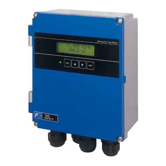
1.3. NAME AND FUNCTION OF EACH PART 1.3.1. Flow transmitter : FSV···S (IP66) (14) (12) (11) (10) (13) Name Description Wiring connection port, large Wiring connection port for power cable and output cable. Wiring connection port, small Wiring connection port for signal cable only. Indication and setting unit Indicates and sets the flow rate, etc. -
Page 12: Flow Transmitter : Fsv
1.3.2. Flow transmitter : FSV···H (IP67) (12) (14) (7) (8) (10) (13) (11) Name Description Wiring connection port Wiring connection port for power cable and output cable. Wiring connection port Wiring connection port for signal cable only. Indication and setting unit Indicates and sets the flow rate, etc. -
Page 13: Installation And Before Start Of Operation Of The Flow Transmitter
Section 6.5.6 Checking received waveforms 5528 to 6758 P/H D Contact Fuji Electric’s service representative. Section 4.7 Zero Adjustment * Before performing zero point adjustment, check that the pipe is filled with fluid, the fluid is in still state, and that the measurement status is normal. -
Page 14: Installation
3. INSTALLATION Select an installation location that satisfies the following conditions for ease of maintenance and inspection, service life of the instrument, and assurance of reliability all considered. AUTION (1) A place where ambient temperature and humidity are -20 to +55°C and 95% RH or less for flow transmitter (FSV) (2) A place not exposed to direct sunshine nor inclement weather. -
Page 15: Installation Of Flow Transmitter
3.2. Installation of flow transmitter The flow transmitter may be mounted on a wall or 2B pipe stand (option). 3.2.1. Wall mounting (Flow transmitter : FSV···S (IP66)) For wall mounting, use two M8 bolts. Drill holes according to the mounting hole dimensions shown below, and fasten the flow transmitter using the M8 bolts. Mounting hole 9 ×... -
Page 16: Wall Mounting
3.2.3. Wall mounting (Flow transmitter : FSV···H (IP67)) For wall mounting, use four M8 bolts. Drill holes according to the mounting hole dimensions shown below, and fasten the flow transmitter using the M8 bolts. Mounting plate Mounting hole 2-φ9 Stainless tag (option) ULTRASONIC FLOW METER STATUS... -
Page 17: Flow Transmitter Wiring
3.3. Flow transmitter wiring 3.3.1. Cautions in wiring AUTION (1) Use a special coaxial cable (FLYC) as a signal cable between the detector and flow transmitter (FSV). Do not provide a junction or splice of the signal cable midway. (2) The signal cable between the detector or flow transmitter should be run in metallic conduits. Upstream and downstream signal cables may be put in the same conduit but, to avoid interference, do not put the power cable together. -
Page 18: Wiring To Each Terminal
3.3.4. Wiring to each terminal 3.3.4.1. Flow transmitter : FSV···S (IP66) Carry out wiring to each terminal according to the following figure. Power supply board terminal block AC power supply DC power supply 100 to 120V AC 20 to 30V DC or 200 to 240V AC 50/60Hz - FG... -
Page 19: Flow Transmitter : Fsv
3.3.4.2. Flow transmitter : FSV···H (IP67) Carry out wiring to each terminal according to the following figure. Communication board terminal block (option) RS-485 SG A- B+ Downstream Power cable Upstream sensor cable sensor cable Output signal cable External (analog output, DO1, ground terminal DO2, Communication) (M4) -
Page 20: How To Connect To Terminal Block
3.3.5. How to connect to terminal block. 3.3.5.1. Cable treatment The cable connecting to the terminal block is available to connect with bare wire but for safety’s sake please crimp the bar terminal to connect. When you cut and use the signal cable, make sure to cut the cable in same length of upstream and downstream. Note) if cable lengths are different, it may adversely affect the output. -
Page 21: How To Connect To Communication
3.3.5.3. How to connect to communication terminal block. Please prepare the flathead screwdriver (head size: 0.6 x 3.5mm) so as to connect the cable. 1. Push the clamp so as to open the connector. 2. Insert the cable to the connector and release the clamp to fix the cable. Clamp -13-... -
Page 22: Parameter
4. Parameter 4.1. Description of display/setting unit Display unit and setting unit are as shown below. 4.1.1. Flow transmitter : FSV···S (IP66) display/setting unit 4.1.2. Flow transmitter : FSV···H (IP67) display/setting unit -14-... -
Page 23: Description Of Display/Setting Unit
4.1.3. Description of display/setting unit ○ LCD display: Displays the measurement and setting (indication in 16 digits, 2 line). “Measurement display” Up to 8 digits including the decimal point are displayed in the data field. When the displayed digits exceed, “<” is displayed at the first digit. When the range exceeds maximum or is below minimum setting, “OVERFLOW”... -
Page 24: Composition Of Key Operation
4.2. Composition of key operation 0.000 m/s 0.000 m3/h Measurement mode PAR.PROTECTIO PROTECTION ON INPUT ID.NO PROTECTION OFF OUTPUT SET UP ZERO ADJUSTMENT CLEAR SET ZERO DAMPING CUT OFF DISPLAY 1ST ROW VELOCITY FLOW RATE FLOW RATE(%) +TOTAL(ACTUAL) +TOTAL PULSE -TOTAL(ACTUAL) -TOTAL PULSE 2ND ROW... - Page 25 BURNOUT TIMER OUTPUT LIMIT LOW OUTPUT LIM.HIGH RATE LIMIT RATE LIMIT TIMER TOTAL UNIT TOTAL MODE START STOP TOTAL RESET TOTAL RATE TOTAL PRESET PULSE WIDTH BURNOUT (TOTAL) HOLD NOT USED BURNOUT TIMER DO1 OUT NOT USED +TOTAL PULSE -TOTAL PULSE FULL SCALE 2 HARDWARE FAULT PROCESS ERROR...
- Page 26 CALIBRATION ZERO CALIBRATION SPAN OPERATION MODE MEASURE SETUP SYSTEM UNIT FLOW UNIT TOTAL UNIT PROCESS SETTING OUTER DIAMETER PIPE MATERIAL WALL THICKNESS LINING MATERIAL LINING THICKNESS (Except for "NO LINING") KIND OF FLUID VISCOSITY SENSOR MOUNT SENSOR TYPE MAINTENANCE MODE RAS INFORMATION CURRENT OUTPUT SETTING...
- Page 27 COMMUNICATION MODE RS-485 BOUAD RATE 9600bps 19200bps 38400bps PARITY NONE EVEN 1 BIT STOP BIT 2 BITS STATION No. PROTOCOL MODBUS M-Flow SYSTEM LANGUAGE ENGLISH JAPANESE GERMAN FRENCH SPANISH REGISTER ID NO. VER. NO. MEMORY INITIALIZE LCD BACKLIGHT * Only for service technician LCD/LED CHECK DATA DISPLAY DETAILS...
- Page 28 SATURATION 128 (Initial value) MEAS.METHOD METHOD 1 METHOD 2 (Initial value) METHOD 3 SIGNAL BALANCE 25% (Initial value) TRANS.PATTERN BURST 1 BURST 2 BURST 3 (Initial value) BURST 4 BURST 5 CHIRP 4 CHIRP 8 RESERVE AGC GAIN AUTO (Initial value) MANUAL U: AGC D: AGC...
-
Page 29: Parameter Initial Value List
4.3. Parameter initial value list Factory-set value is shown below. (When parameter setting is not provided.) Setting unit Setting range Initial value Setting value Parameter protection No. of menu: 2 PROTECTION ON PROTECTION ON, PROTECTION OFF ID No 0000 to 9999 0000 ID No. - Page 30 Setting unit Setting range Initial value Setting value DO1 output type No. of output content Not used Not used +Total pulse menu: 10 No. of alarm menu: 3 -Total pulse Flow switch range Range full scale 2 0 to 32m/s in terms of Alarm [All, Device error, Process error] flow velocity Flow rate switch...
-
Page 31: Parameter Protection
4.4. Parameter protection 4.4.1. Protection ON/OFF Description Parameters can be protected so that the flow meter settings will not carelessly be changed. Parameters can be protected by setting the "ID No." (Note) in the maintenance mode. Note) 4 digits are factory set at "0000". (Refer to Section 4.11.7.) Setting range: PROTECTION ON : Parameter cannot be changed. -
Page 32: Display Language
4.5. Display language 4.5.1. How to select the language Description Indication language (English, Japanese, German, French, Spanish) is selectable. Setting contents English (default setting), Japanese, German, French, Spanish For actual keying, refer to the typical operation indicated below. Set the protection to OFF beforehand. (See Section 4.4.1.) Operation Select English for the display language. -
Page 33: Specifications/Detector
4.6. Checking and Setting of Piping Specifications/Detector 4.6.1. Checking piping parameter Key operation Description Display 0.000 0.000 m3/h MEASURE SETUP Press the key for 3 times to display “MEASURE SETUP”. ▼ SYSTEM UNIT Press the key once to display “SYSTEM UNIT”. ENGLISH ▼... -
Page 34: Piping Parameter Setting Method
4.6.2. Piping parameter setting method Description Set the parameters of piping and fluid to be measured to determine the sensor mounting spacing. The mounting dimension of the sensor is automatically calculated. Refer to “5.1.1 PRODUCT OUTLINE”. AUTION Be sure to set the following parameters before mounting the sensor on the pipe. Mount the sensor to match the sensor mounting length. - Page 35 OUTER DIAMETER Press the key once to register the outer diameter. COMPLETE ▼ ↓ ――― Outer diameter has been registered. ――― ▼ OUTER DIAMETER ▼ 114.00 mm ▼ PIPE MATERIAL Press the key once to display “PIPE MATERIAL”. ▼...
- Page 36 (2) Setting method when sensor type is not “FSSA” Operation Carry out setting for measuring the flow rate of water flowing through PVC pipe (for tap water) having 100 mm of (example) nominal diameter, using FSSC detector. * Settings of piping and fluid to be measured are omitted, since it is same as “(1) Setting method when sensor type is “FSSA”...
-
Page 37: Zero Adjustment
4.7. Zero Adjustment Description Zero point is calibrated. Settable range: CLEAR : Clears the zero point calibration value to "0". Used in case the flow cannot be stopped when calibrating the zero point. Note 1) Where possible, stop the flow and carry out "SET ZERO" stated below. Otherwise, an error may occur in the zero point. -
Page 38: Setting Of Unit
4.8. Setting of unit 4.8.1. How to set the unit system Description Measurement unit can be selected from metric or inch system. Metric system (factory set) Length ······································ mm Flow velocity ······························ m/s Flow rate ·································· L/s, L/min, L/h, L/d, kL/d, ML/d, m /s, m /min, m /h, m... -
Page 39: How To Set The Flow Rate Unit
4.8.2. How to set the flow rate unit Description Select the unit of flow rate. Metric system Flow rate ········ L/s, L/min, L/h, L/d, kL/d, ML/d, m /s, m /min, m /h (factory set), m /d, km /d, Mm /d, BBL/s, BBL/min, BBL/h, BBL/d, kBBL/d, MBBL/d <Note>... -
Page 40: How To Set The Total Unit
4.8.3. How to set the total unit Description Select the unit of total volume. Metric system Total unit ········ mL, L, m (factory set), km , Mm , mBBL, BBL, kBBL <Note> First, set the unit system (metric) according to Section 4.8.1. When setting, stop status should be set at total mode. -
Page 41: Output Setting
4.9. Output Setting 4.9.1. Setting of flow rate range 4.9.1.1. Setting of flow rate range (single range) Description 20mA The range (full scale) of flow rate to be measured is set. * The analog output (4-20mA) corresponds to the range setting. ... - Page 42 0.000 Press the key for 2 times and then press the key for 3 times to 0.000 m3/h enter the measurement mode. -34-...
-
Page 43: Setting Of Analog Output At Error
4.9.1.2. Setting of analog output at error (Burnout) Description Determine how to set the analog output when received wave error, etc. due to device error, accidental drain of piping or entry of bubbles. Settable range Analog output (4-20mA) at error HOLD (factory set) : Outputs a current value preceding the error. -
Page 44: Output Limit
4.9.1.3. Output limit Description Analog output Upper and lower limits can be set within the range of analog output 0.8mA Upper limit to 23.2mA (-20% to 120%). 23.2mA Settable range (1) Output lower limit: -20% to 0% (0.8mA to 4mA) 20mA Output upper limit: 100% to 120% (20mA to 23.2mA) Lower limit... -
Page 45: Setting The Total(Actual)
4.9.2. Setting the total(actual) 4.9.2.1. Setting the total pulse (total rate, pulse width) Description Set to totalize a process variable (flow rate) by total meter, etc. according to total pulse output. Total rate : Total amount (volume) per pulse. A pulse is outputted when the total volume has attained an amount set by the pulse value, and adds to the total pulse count (in case of total pulse indication). -
Page 46: Width)
Operation Set total value to 0.1m /pulse, and pulse width to 100ms. (example) * Set the total value beforehand. Key operation Description Display OUTPUT SETUP Press the key twice to display “OUTPUT SETUP”. ▼ ZERO ADJUSTMENT Press the key once to display “ZERO ADJUSTMENT”. SET ZERO ▼... -
Page 47: Setting The Preset Value
4.9.2.2. Setting the preset value Description Preset value: Value which appears on the total counter when the total value has been reset. Settable range:0 to 99999999 <Note> A resetting action simultaneously resets both forward total memory and reverse total memory. Set the total unit beforehand in the MEASURE SETUP mode. -
Page 48: Total Mode
4.9.2.3. TOTAL mode (total reset, start, stop) Description The total is started, stopped or reset. Settable range: START, STOP, TOTAL RESET START : Starts totalizing. Totalizes continuously from the stopped status. STOP : Stops totalizing. Setting cannot be changed when it is not stopped. RESET : Resets the total memory to the reset value, and starts totalizing. -
Page 49: Determining How To Dispose Of Total At Error (Burnout)
4.9.2.4. Determining how to dispose of total at error (BURNOUT) Description BURNOUT (TOTAL) Determines how to dispose of the total when the measurement status is abnormal on account of an empty pipe interior or bubbles mixed in fluid (common to total indication and total pulse output). ... -
Page 50: Setting The Do Output
4.9.3. Setting the DO output Description Selects the output of total pulses and statuses (of alarm, flow switch, total switch, etc.). Settable range (common to DO1, DO2 ) NOT USED : Does not use the contact output. +TOTAL PULSE : Outputs the forward total pulses. - Page 51 ▼ ――― “+TOTAL PULSE” has been registered. ――― STATUS OUT ▼ CONTACT ACTION ▼ CONTACT ACTION Press the key once to display “CONTACT ACTION”. ACTIVE ON ▼ CONTACT ACTION Press the key once to register “ACTIVE ON” (normally off). COMPLETE ▼...
-
Page 52: Setting The Lcd Indication
4.9.4. Setting the LCD indication Description Flow velocity indication Selectable flow velocity units: m/s (if SYSTEM UNIT was set to METRIC) (See 4.8.1) <Note> The decimal point position is fixed. (Decimal point 3 digits) Flow rate indication Selectable flow rate indications: Actual value reading, % reading. <Note>... -
Page 53: Setting The Damping
4.9.5. Setting the damping Description Used for attenuating the variation of measured value. A time constant is set (response time of about 63%). Settable range: 0.0 to 100.0sec in 0.1 sec steps Note) In case you set to 0 sec, response time become as below. ... -
Page 54: Setting The Low Flow Rate Cutting
4.9.6. Setting the low flow rate cutting Description The output can be cut when the flow rate is too small. Output Effective for indication, analog output (4-20mA) and total operation. Settable range: 0 to 5 [m/s] in terms of flow velocity. (Factory set: 0.150 [m /h]) Note 1) As required, set the low flow rate cut because the flow meter may read a... -
Page 55: Application Operation Of Parameter
4.10. Application operation of parameter 4.10.1. Setting automatic 2 ranges Description The function carries out a measurement while changing over the range 20mA according to the flow rate. The current output changes with the action range as illustrated on the right. ... - Page 56 FULL SCALE2 Press the key once to display “FULL SCALE2”. 0.0000 m3/h ▼ FULL SCALE2 Press the key once to blink the cursor. 0000.0000 m3/h ▼ FULL SCALE2 Press the key twice to move the cursor. 0000.0000 m3/h ▼ FULL SCALE2 Press the key for 6 times to set “6”.
-
Page 57: Setting The Bi-Directional Range
4.10.2. Setting the Bi-directional range Description 20mA The function measures the flow rate of either forward or reverse flow while changing over the range corresponding to the flow direction. The current output changes with the action range as illustrated on the right. ... - Page 58 FULL SCALE2 Press the key once to register. 0000.0000 m3/h ▼ FULL SCALE2 Press the key several times to display “-” on the 1st line. -000.0000 m3/h ▼ FULL SCALE2 Press the key twice to move the cursor. -000.0000 m3/h ▼...
-
Page 59: Setting The Bi-Directional Auto 2 Range
4.10.3. Setting the Bi-directional auto 2 range Description Analog output The function measures the flow rate of either forward 20mA or reverse flow while changing over the range corresponding to the flow direction. The current output changes with the action range as illustrated on the right. - Page 60 ▼ ――― FULL SCALE1 has been registered. ――― FULL SCALE1 ▼ 10.0000 m3/h ▼ FULL SCALE2 Press the key once to display “FULL SCALE2”. 0.0000 m3/h ▼ FULL SCALE2 Press the key once to blink the cursor. 0000.0000 m3/h ▼ FULL SCALE2 Press the key twice to move the cursor.
-
Page 61: Rate Limit
4.10.4. Rate limit Description Spike noise input such as slurry fluid can be cut and output. Settable range (1) RATE LIMIT 0 to 5 [m/s] in terms of flow velocity. Absolute value is input (Factory set: 0[m /h]) (2) RATE TIMER Enter in the range of 0 to 900 sec. - Page 62 RATE LIMIT TIMER Press the key once to register. COMPLETE ▼ ↓ ▼ ――― RATE LIMIT TIMER has been registered. ――― RATE LIMIT TIMER ▼ 10 sec ▼ 0.000 Press the key twice and then press the key for 3 times to enter 0.000 the measurement mode.
-
Page 63: Setting The Do Output
4.10.5. Setting the DO output 4.10.5.1. How to validate outputting the FULL SCALE 2 Description Select a contact output as DO1 and/or DO2 at FULL SCALE2 measurement status. For actual keying, refer to the typical operation indicated below. Set the protection to OFF beforehand. (See Section 4.4.1.) Operation Set the DO1 output to “FULL SCALE2”. -
Page 64: How To Validate The Alarm Output
4.10.5.2. How to validate the alarm output Description Select a contact output as DO1 and/or DO2 when received wave or E PROM is abnormal. Settable range : Select a contact output when hardware and received wave (nothing, unstable) are abnormal. HARDWARE FAULT : Select a contact output when circuit is abnormal. -
Page 65: Setting The Flow Switch
4.10.5.3. Setting the flow switch Description Select a contact output as DO1 and/or DO2 when the flow rate has exceeded a setting. In case of FLOW SW HIGH SWITCH In case of FLOW SW LOW SWITCH Flow rate Flow rate Hysteresis Hysteresis Time... - Page 66 ▼ ――― “ACTIVE ON” has been registered. ――― STATUS OUT ▼ CONTACT ACTION 0.000 Press the key twice and then press the key for 3 times to enter 0.000 the measurement mode. -58-...
-
Page 67: How To Validate The Total Switch
4.10.5.4. How to validate the total switch Description Total value Select a contact output as DO1 and/or DO2 when the total value exceeds a setting. Settable range: 0.000001 to 99999999 Setting value Contact action: ACTIVE ON : DO1/DO2: Normally off ACTIVE OFF : DO1/DO2: Normally on Note) Different values can be assigned to DO1 and DO2. -
Page 68: How To Validate The Range Over Output And Pulse Range Over Output
4.10.5.5. How to validate the range over output and pulse range over output Description AO RANGE OVER : Select a contact output as DO1 and/or DO2when the upper limit and lower limit output are above the setting. PULSE RANGE OVER : Select a contact output as DO1 and/or DO2 when the total pulse output exceeds the maximum output frequency value. -
Page 69: How To Validate The Output At The Minus
4.10.5.6. How to validate the output at the minus direction action Description Select a contact output as DO1 and/or DO2 when the flow is in reverse direction. For actual keying, refer to the typical operation indicated below. Set the protection to OFF beforehand. (See Section 4.4.1.) Operation Set the DO1 output to “-:FLOW DIRECTION”. -
Page 70: How To Compensate The Measurement
4.10.6. How to compensate the measurement value Description Output Output Measurement value can be calibrated arbitrarily. 100% Zero point and span adjustment can be made. Settable range (1) Zero point : -5 to +5 [m/s] in terms of flow velocity in piping. -
Page 71: Setting Of The Operation Mode
4.10.7. Setting of the operation mode Description Used to switch computation cycle and output cycle. Settable range NORMAL : Standard mode (factory-set value), computation/output cycle is approximately 0.5 seconds. HIGH SPEED : High speed response mode, computation/output cycle is approximately 0.2 seconds. For actual keying, refer to the typical operation indicated below. -
Page 72: Maintenance Mode
4.11. MAINTENANCE MODE 4.11.1. How to calibrate the analog output Description The calibration is performed so as to obtain 4mA and 20mA when the analog signal (4-20mA DC) output is 0% and 100%, respectively. Connect an ammeter to Iout terminals as shown below. In the CURRENT CALIBRATION mode, select 4mA or 20mA, and operate the key (UP) or the key (Down). -
Page 73: How To Set The Constant Current Output
4.11.2. How to set the constant current output Description Generates a fixed value output of analog signal. Application example: The operation of a connected receiver is checked by generating a fixed value output of analog signal. n the constant current setting mode (OUTPUT SETTING), set the constant current output value. Settable range: -20%(0.8mA) to +120%(23.2mA) For actual keying, refer to the typical operation indicated below. -
Page 74: How To Check The Action Of Total Pulses
4.11.3. How to check the action of total pulses Description Checks the action of total pulse output. The output action can be checked upon designating the number of pulses to be outputted per second. Settable range: 1 to 100 pulses/s (when pulse width is 5ms, 10ms, 50ms,100ms or 200ms) Note 1) The output pulse width is as selected currently. -
Page 75: How To Check The Status Output
4.11.4. How to check the status output Description Check the status output. Setting content ON: Close the contact. OFF: Open the contact. AUTION This operation sets DO1 and DO2 the same contact action. Before operation, check whether DO output testing is permitted. For actual keying, refer to the typical operation indicated below. -
Page 76: How To Validate The Test Mode
4.11.5. How to validate the test mode (simulated flow rate output) Description Flow rate output Checks different outputs (LCD indication, analog output, DO output) upon simulating flow rate outputs. With the output at the actuated time as an initial value, the output changes up to the input value (simulated flow rate target value) in a selected TRACKING TIME, and at Input value the input value, the output value becomes constant. - Page 77 TRACKING TIME Press the key once to register. COMPLETE ▼ ↓ ▼ ――― “TRACKING TIME” has been registered. ――― TRACKING TIME ▼ 100 s ▼ * Simulating flow rate output is started. 0.00 Display the measurement mode by the key and the key.
-
Page 78: How To Validate A Serial Transmission
Station No. : 1 to 31 (factory set: 1) Communication protocol : MODBUS RTU mode (factory set) or M-Flow (Fuji Electric’s M-Flow [Type: FLR] protocol) Note) For the transmission specifications, refer to the separate instruction manual “Ultrasonic Flowmeter Communication functions” (INF-TN5A1564-E). - Page 79 ▼ ――― STATION No. has been registered. ――― STATION No. ▼ ▼ PROTOCOL Press the key once to display “PROTOCOL”. MODBUS ▼ Because “MODBUS” is set, setting is completed. To select other protocol, press the key, and select a protocol by the key, and register it by the key.
-
Page 80: How To Set The Id No
4.11.7. How to set the ID No. Description Set the ID No. for parameters (Section 4.4.1). If ID No. is set, the number must be inputted before canceling the protection. To validate the protection, set the protection to "ON". (See Section 4.4.1.) ID No. -
Page 81: Initializing Setting Parameters
4.11.9. Initializing setting parameters Description Initializes the setting parameters saved in the memory. Initializes those other than the zero adjusted values or analog output calibration value. AUTION Initialize code: 0100 (4-digit number) This parameter is intended for our service personnel. ... -
Page 82: Lcd Backlight Setting
4.11.10. LCD backlight setting Description Sets the operation of the LCD backlight. You can set that light is ON all the time/ light is OFF all the time/ light is ON only when key operation and light is OFF at setting time. Setting content ON: LCD backlight is ON all the time. -
Page 83: How To Set The Detailed Setting
4.11.11. How to set the detailed setting Description The data required for time difference measurement can be set as follows. AUTION This parameter is intended for our service personnel. Do not change the setting by yourself. Otherwise measurement may be disabled. ... - Page 84 *1) Forward-direction signals are taken in with forward total time measurement, while reverse-direction signals are taken in with reverse total time measurement. They are conducted alternately for the transmission count. Forward and reverse signal data is added for the transmission count and averaged. The result is 1 output of signal in forward/reverse direction. [Outline drawing of signal processing] Forward total time measurement Reverse total time measurement...
-
Page 85: Mounting Of Detector
5. Mounting of detector 5.1. Detector mounting procedure Mount the sensor on the pipe, and perform the following steps in order before making measurement. Reference Work item : Outline steps section Selection of mounting method : Check the V/Z method, pipe size, and detector. Mounting method on the pipe : Apply acoustic couplant to the detector oscillation surface, and connect the sensor cable. -
Page 86: Mounting Of Detector
5.1.1. Mounting of detector For sensor spacing, select either method in advance. Calculate from flow transmitter Turn ON the flow transmitter. Enter the piping information, etc described in Section 4.6.2, and display it. Display example: PROCESS SETTING S=16 ( 48mm) During wiring work, be sure to turn the power off. -
Page 87: Selection Of Mounting Method
5.2. Selection of mounting method There are 2 methods for mounting the detector; V method and Z method. (See Fig. 5-1.) Detector Detector V method Z method Fig. 5-1 Mounting method The Z method should be used in the following cases. ... -
Page 88: Check And Maintenance
6. CHECK AND MAINTENANCE 6.1. Daily Check Visually check the following items. Whether flow transmitter cover screws are loose. Tighten. Whether cable glands are loose. Tighten. Whether detector mounting band is loose. Stretch. Whether received wave is abnormal (LED lit red). Check whether piping is filled or not. Remove bubbles or foreign matters, if mixed in measurement pipe. -
Page 89: How To Measure The Insulation Resistance
6.2.3. How to measure the insulation resistance 6.2.3.1. Flow transmitter : FSV···S (IP66) AUTION Turn off power before opening the flow transmitter cover. The power terminals are provided with an arrester as standard. Measurement point: measure between power terminal and ground terminal, each outputs and ground terminal. The insulation resistance performance of the equipment is 100 MΩ/500 V DC. -
Page 90: Flow Transmitter : Fsv
6.2.3.2. Flow transmitter : FSV···H (IP67) AUTION Turn off power before opening the flow transmitter cover. The power terminals are provided with an arrester as standard. Measurement point: measure between power terminal and ground terminal, each outputs and ground terminal. The insulation resistance performance of the equipment is 100 MΩ/500 V DC. -
Page 91: How To Replace The Fuse
6.3. How to replace the fuse AUTION Be sure to turn off the power before replacing the fuse. Fuse specifications (1) AC power supply (100V and 200V): 5.0m (diameter) × 20mm (long), 250V, 0.5A. Clearing characteristics (T), breaking capacity (L) Example: 0218.500MXP 250V, 0.5A manufactured by littelfuse. -
Page 92: Flow Transmitter : Fsv
6.3.2. Flow transmitter : FSV···H (IP67) (1) Opening the cover after turning off power. Loosen 4 screws from the flow transmitter front, and open the cover. (2) Loosen 2 screws from the setting section of the display unit, and open the cover. (3) Replace the fuse. -
Page 93: How To Replace The Lcd
6.4. How to replace the LCD The nominal service life of the LCD is 7 years. The contrast gradually deteriorates with time. Replace it about 5 years after starting its use. 6.4.1. Flow transmitter : FSV···S (IP66) [How to replace] (1) Open the cover after turning OFF power. -
Page 94: Flow Transmitter : Fsv
6.4.2. Flow transmitter : FSV···H (IP67) [How to replace] (1) Open the cover after turning OFF power. (2) Loosen 2 screws from the setting section of the display unit, and open the cover. (3) Remove the flat cable connector. (4) Remove the LCD cable connector. (5) Loosen 3 screws from mainboard. -
Page 95: Error And Remedy
6.5. ERROR AND REMEDY 6.5.1. Display error State Probable cause Power supply is not turned on. Low power supply voltage Fuse is blown out. Nothing is displayed. LCD error Refer to “6.5.7. Remedying a hardware fault”. ... -
Page 96: Checking The Led Lit In Red
6.5.1.2. Checking the LED lit in red Check the LED lit in red, following the procedure shown below. LED lit in red Check the RAS information The 2nd or 3rd from the left is 1. 0110000000000000 Error status: Device error, Ultrasonic send/receive signals cannot be collected. -
Page 97: Checking The Ras Information
6.5.1.3. Checking the RAS information When the red LED lights up, check the error contents according to the RAS information. Key operation Description Display Press the key for 4 times to display “MAINTENANCE MODE”. MAINTENANCE MODE ▼ Press the key once to display “RAS INFORMATION”. RAS INFORMATION 0000000000000000 If the display is abnormal, 1 is set. -
Page 98: Displaying The Data In Maintenance Mode
6.5.2. Displaying the data in maintenance mode Follow the procedure shown below to check possible display errors. Key operation Description Display MAINTENANCE MODE Press the key for 4 times to display “MAINTENANCE MODE”. ▼ RAS INFORMATION Press the key once to display “RAS INFORMATION”. 0000000000000000 ▼... -
Page 99: Keying Is Abnormal
6.5.3. Keying is abnormal Status Probable cause No response is made to key input. Hard failure Refer to “6.5.7. Remedying a hardware fault”. Certain key is not responded. Action is not as defined. -91-... -
Page 100: Error In Measured Value
6.5.4. Error in measured value Status Probable cause Troubleshooting Connection between main unit and The reading appears with Connect properly. “-” (minus). sensor units (upstream, downstream) are inverted. Flow of fluid is reversed. Measured value Straight pipe length is inadequate. Move the sensor to the place where the fluctuates though flow length of 10D can be assured on... - Page 101 Status Probable cause Troubleshooting (Continued from the High turbidity previous page.) Turbidity is higher than those of sewage and return sludge. Pipe is old and scale is attached on inside. Move sensor to a place of smaller Lining is thick.
-
Page 102: Error In Analog Output
6.5.5. Error in analog output Status Probable cause Troubleshooting Current output is not Range setting is wrong. Set the range correctly. matched. Not 4mA when Analog output is misadjusted. Perform analog output calibration. measurement value is 0. Output is 0mA. Break of wiring Output rises beyond “OVER FLOW”... -
Page 103: Checking Received Waveforms
6.5.6. Checking received waveforms The unit has high-voltage part. Be sure to ask our service personnel for the steps described below. 6.5.6.1. How to connect the oscilloscope Open the cover, and connect an oscilloscope to the check pin on the printed board according to the following figure. The unit has high-voltage components. -
Page 104: Checking Sending/Receiving
6.5.6.2. Checking sending/receiving Monitor the waveform, and check the status of received waveform. a) Normal status CH1 : 500mV/div CH1 (SMP) CH2 : 5V/div CH2 (SIG) Noise level Point 1. Check that overall noise level is kept at 0.3 Vp-p or lower. Forward direction Reverse direction Forward direction... - Page 105 Startup of signals is not good Trigger Trigger wave height The same forms near the trigger level. Startup of signals is not good There is not large difference among triggering waveform. Cause of the poor startup signals (1) Incorrect detector mounting, dimensions (sensor mounting dimension, outer diameter, etc) and detector mounting angle Displacement from the Displacement of the...
-
Page 106: Remedying A Hardware Fault
Outer shielding of the dedicated cable is grounded Ground to the earth. 6.5.7. Remedying a hardware fault If the hardware is found faulty as a result of Section 6.5.1 to Section 6.5.6 above, provide specific details to Fuji Electric. -98-... -
Page 107: Appendix
7. Appendix 7.1. Specifications SPECIFICATIONS Functional Analog signal: 4 to 20mA DC (1 point) Operational Load resistance: 600Ω max. Digital output: Forward total, reverse total, alarm, System assignable arbitrarily (Model FSV) and a detector (Model FSS) Transistor contact (isolated, open collector) Applicable •... - Page 108 External terminal of transmitter: plug terminal (ESC, , , ENT) Zero adjustment: Set zero/Clear available PC Loader software Damping: 0 to 100s (every 0.1s) for analog output Provided as standard rate cutoff: •Compatible model is PC/AT compatible instrument. Alarm: Digital output available for Hardware •Main functions: Software for Main unit parameter setting/ fault or Process fault change on PC...
-
Page 109: Outline Diagram
7.2. OUTLINE DIAGRAM Flow transmitter (Type: FSVY2-S) U bolt ( 8) Unit : mm (option) tg. plate tg. hole Ultrasonic Flow eter TI E DELTA-C SS tag (option) Cable gland tg. pipe Earth terminal ( 4) For sensor cable (PF3/8) For power supply &... -
Page 110: Ordering Information
7.3. ORDERING INFORMATION 1. Type of detector 2. Type of flow transmitter 3. Type of signal cable 4. Tag No. (When tag plate is specified) 5. Parameter setting list (When parameter setting is specified) Company name Branch: Name of the contact person: TEL: Measuring fluid: Parameter setting list... -
Page 111: Piping Data
7.4. Piping data Stainless steel pipe for pipe arrangement (JIS G3459-2012) Thickness Nominal Outer Schedule Schedule Schedule Schedule Schedule Schedule Schedule diameter diameter Thickness Thickness Thickness Thickness Thickness Thickness Thickness 21.7 1.65 27.2 1.65 34.0 1.65 1 1/4 42.7 1.65 1 1/2 48.6 1.65... - Page 112 Polyethylene pipe for general use (JIS K6761-2004) IWVP : PVC pipe (ISO 4422-2) 1st type 2nd type Nominal Outer Outer Pipe Nominal (Soft pipe) (Hard pipe) diameter of diameter diameter thickness diameter pipe Thickness Thickness (mm) (mm) (mm) ND32 21.5 ND40 ND50 27.0...
- Page 113 Coated steel pipe for city water STW (JIS G3443-1 2007) Symbol for type STW 400 Nominal Outer STW 290 STW 370 Nominal thickness diameter diameter (mm) Thickness Thickness Thickness Thickness (mm) (mm) (mm) (mm) 89.1 114.3 139.8 165.2 216.3 267.4 318.5 355.6 406.4...
- Page 114 Arc welded large-diameter stainless steel pipe for pipe arrangement SUS (JIS G3468-2011) Nominal thickness Nominal diameter Outer Schedule Schedule Schedule Schedule diameter (mm) Thickness Thickness Thickness Thickness 165.2 216.3 267.4 318.5 10.3 355.6 11.1 406.4 12.7 457.2 14.3 508.0 15.1 558.8 15.9 609.6...
- Page 115 Cast iron pipe for waste water FC150 (JIS G5525:2000) Mechanical type Insertion type 1st type pipe 2nd type pipe RJ pipe Nominal Straight/deformed Straight pipe Deformed pipe Straight pipe Deformed pipe diameter pipe Outer Pipe Outer Pipe Outer Pipe Outer Pipe Outer Pipe...
- Page 116 PVDF-HP Heat-resistant hard vinyl chloride pipe PVC-C (JIS K6776:2007) SDR33 SDR21 SDR17 S16 PN10 S10 PN16 S8 PN20 Outer Nominal Thickness Weight diameter Outer diameter (mm) (kg/m) Thickness Thickness Thickness (mm) diameter (mm) (mm) (mm) (mm) 18.0 0.180 22.0 0.265 26.0 0.321 32.0...
- Page 117 (a) Velocity of sound subject to change f temperature of water (0 to 100 C) T °C V m/s T °C V m/s T °C V m/s T °C V m/s 1402.74 1407.71 1499.64 1543.93 1555.40 1412.57 1502.20 1544.95 1555.31 1417.32 1504.68...
- Page 118 (d) Kinematic viscosity coefficient of various liquids ρ g/cm ν ( Name of liquid T °C V m/s × Acetone 0.7905 1190 0.407 Aniline 1.0216 1659 1.762 Ether 0.7135 1006 0.336 Ethylene glycol 1.1131 1666 21.112 Chloroform 1.4870 1001 0.383 Glycerin 1.2613 1923...
Need help?
Do you have a question about the Time Delta-C FSV-2 and is the answer not in the manual?
Questions and answers