
Related Manuals for Fuji Electric FSC-2


Summary of Contents for Fuji Electric FSC-2
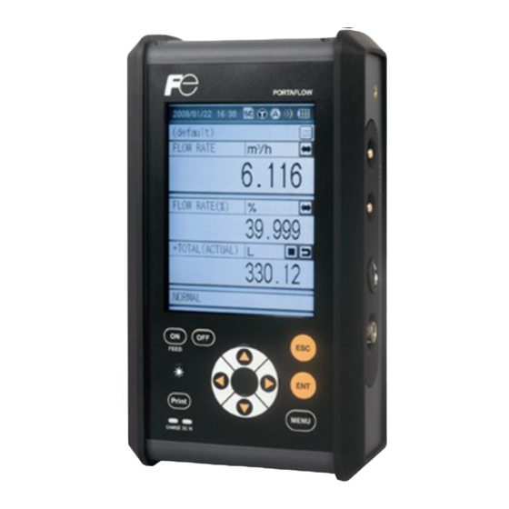
- Page 1 Instruction Manual PORTABLE TYPE ULTRASONIC FLOWMETER TYPE: FLOW TRANSMITTER FSC-2 DETECTOR FSS-1, FSD-1 INZ-TN2FSCd-E...
- Page 2 Keep this manual available for reference by appropriate operation and maintenance personnel. Option The following options are available. • Flow velocity profile measurement Manufacturer : Fuji Electric Co., Ltd. Type : Described in nameplate on main frame Date of manufacture : Described in nameplate on main frame Product nationality : Japan Note) Windows 2000/XP/Vista/7, Excel, Bitmap are registered trade marks of Microsoft Corporation.
- Page 3 CONTENTS 1. OVERVIEW ..........................1 2. CHECK OF DELIVERED ITEMS ..................2 On purchase of flow transmitter (type: FSC)..................2 On purchase of transit time detector (type: FSS) ................3 On purchase of flow velocity distribution measurement detector (type: FSD) .........4 3. CHECK MODEL AND SPECIFICATION ................5 4.
- Page 4 Processing of mounting surface .......................44 How to mount FSSC to pipe ......................45 8.4.1 How to mount a detector (V method) ..................45 8.4.2 How to mount a detector (Z method) ..................48 8.4.3 Method of mounting bely ......................50 How to mount FSSD to pipe ......................53 8.5.1 How to mount a detector (Z method) ..................53 8.5.2 How to mount a type (V method) .....................54 How to attach the medium size detector ..................56...
- Page 5 10.6 Maintenance function (MAINTENANCE screen) ................123 10.6.1 Checking receiving status for transit time ................123 10.6.2 Check for analog input/output ....................128 10.6.3 SD memory card ........................130 10.6.4 LCD check ..........................133 10.6.5 Software ..........................134 10.7 Flow velocity distribution display function (optional) ..............136 10.7.1 Installing Detector ........................136 10.7.2 Operation ..........................141 10.8 Contents of errors in status display....................146...
- Page 6 WARNING SYMBOLS AND THEIR MEANINGS Be sure to observe the following precautions. They offer important information on safety. Operating this device in a manner not specified may damage its protective construction. ● The degree of injuries or damages resulting from improper handling of this device is indicated by different symbols.
- Page 7 SAFETY PRECAUTIONS Be sure to read this “Safety Precautions” carefully beforehand for the correct and safe use of this device. WARNING Do not touch the switch with a wet hand. Do not break or pull the power cord. Do not touch the switch Do not put heavy items with a wet hand.
- Page 8 CAUTION Keep warning labels clean. Inspect the power plug periodically. Inspect the power plug once Clean or replace the warning every 6 months. Wipe the dust labels so that they can always be off the plug and insert it securely. read correctly.
- Page 9 CAUTION Cause of machine malfunction. Cause of machine malfunction. Use in a place which is remote Do not use in a place which is from electrical devices (motor, near cell phones, wireless devices, etc., which may cause transformer, etc.) which generate the machine blunder.
- Page 10 1. OvERvIEW This Portable type ultrasonic flowmeter is a portable type ultrasonic flowmeter that allows easy measure- ment of flow rates in pipes by installing a sensors on the outside of pipes. A combination of the latest electronics and digital signal processing technologies enables the instrument to provide a compact and convenient solution to accurately measure system flow rates without breaking or opening the serial transmission and removable memory card functionality allow easy date acquisition and analysis.
- Page 11 2. CHECK OF DELIvERED ITEMS On purchase of flow transmitter (type: FSC) Without printer (FSC ) Conversion unit Carrying case With printer (FSC ) Strap Signal cable AC power supply (5m×2 pcs) adapter Power connector conversion cord CD-ROM Instruction manual (INF-TN2FSC-E) Power cord Loader Instruction...
- Page 12 On purchase of transit time detector (type: FSS) Be sure to check whether following parts are obtained or not after opening the package. Note that delivered items vary depending on the type. <Detector> 4th digit of code symbol <Mounting belt> 6th digit of code symbol FSS**□ FSSC: Rail ……………………………1 set A: Stainless steel belt …………………2 pieces Sensor unit ……………………2 pieces...
- Page 13 On purchase of flow velocity distribution measurement detector (type: FSD) The following parts are included. (1) Main unit Small type (Type: FSDP2) Large type (Type: FSDP0) Middle type (Type: FSDP1) (2) Accessories Kind of Small type Medium type Large type Quantity Remarks detector •...
- Page 14 3. CHECK MODEL AND SPECIFICATION The specification plates attached to the frame of flow transmitter and the detector list the type and specifi- cations of the product. Check that they represent the type ordered, referring to the following code symbols. <Flow transmitter: FSC> 1 2 3 4 5 6 7 8 9 10 11 Description...
- Page 15 <Water-proof treatment> (9th digit) None None <Tag plate> (10th digit) Provided (with signal cable 10m) None Provided <Tag plate> (10th digit) None Provided Type. Ser.No. Ultrasonic Flow Meter Mfd. Fuji Electric Co., Ltd. Made in Japan Type Ser.No. Mfd. Made in Japan INF-TN2FSC-E...
- Page 16 <Flow velocity detector: FSDP> 1 2 3 4 5 6 7 8 0 Y 1 Description <Kind> Small type (φ40 to φ200mm) Middle type (φ100 to φ400mm) Large type (φ200 to φ1000mm) <Application> None <Structure> General use Modification No. Small type (Type: FSDP2) Large type (Type: FSDP0) Middle type (Type: FSDP1) INF-TN2FSC-E...
- Page 17 4. NAME AND EXPLANATION OF EACH PART Name and explanation of main unit and detector Printer Detector Rubber Signal cable Display window Keyboard • Keyboard : Used for turning on/off power supply of the main unit, controlling the printer, inputting fluid specifications and setting the function of ULTRASONIC FLOWMETER.
- Page 18 AI/AO (4 to 20mA DC analog I/O connector) 12V DC UP STREAM (power connector) (detector connector on upstream side) DOWN STREAM (detector connector on downstream side) Right side LCD contrast adjusting knob Note SD memory card Note) SD logo is a registered trademark. Bottom • Connectors : 12V DC Connector of main unit power supply.
- Page 19 Explanation of keys Fig. 3-1 shows the layout of keys and Table 3-1 explains each key. Fig. 4-1 Layout of keys Table 4-1 Explanation of keys Key indication Description or lamp The keyed-in data, selected item, etc. will be set by pressing this key. Cancels any setting.
- Page 20 Handling of SD memory card Use an SD memory card for recording measured data, flow velocity profile data and screen data. The equipment is capable of accommodating an SD memory card of capacity up to 8gB. An SD memory card of capacity 512MB is provided as an option. Compatible media •...
- Page 21 4.3.3 Insertion and removal Methods for insertion and removal of an SD memory card are described below. (1) Insertion Step 1) Open the cap from the main unit bottom face. SD memory card slot Step 2) Insert a memory card into the memory card slot in the main unit bottom face in the direction shown on the right.
- Page 22 4.3.4 Data recording to SD memory card (1) Types of recorded data Recorded data is of three different types indicated below. (1) Measured data: One logger file is composed of a configuration file and a data file. Configuration file: Records logger start-up time and relevant logger data files.
- Page 23 Root Site name VALVE_Open_20060703_163100.ini (Folder) (File) Log name Date Time VALVE_Open_20060703_163100.csv (File) Logger Log name Date Time VALVE_Open_20060705_183100.csv (File) Log name Date Time QUICK_20060704_163100.ini (File) Quick logger QUICK_20060703_163100.csv (File) Date Time Flow velocity distribution Vel_20060704_163100.csv (File) Data Time Vel_20060705_163100.csv (File) Date Time Hard copy DISP_20060704_163100.bmp...
- Page 24 (3) Recording capacity The recording capacity depends on the capacity of the SD memory card. One logger file is composed of a configuration file and a data file. The data file is stored as divided by 65,500 lines for permitting high-speed access and due to restrictions in the maximum number of lines of CSV display of Microsoft Excel.
- Page 25 5. CHARGE METHOD AND OPERATION POWER SUPPLY Operating power supply There are two available methods for operating main unit ; by the built-in battery or with the power adapter. (1) How to charge the built-in battery. Please be sure to charge the buid-in battery as following procedure. (1) Connect the AC power adapter to the main unit.
- Page 26 (2) Operating by build-in battery (1) When turning on the power supply of the main unit without connecting the AC power adapter, the main unit be operated by the built-in battery. Whne main unit does not work, voltage reduction of battery is considered. Be sure to charge the buid-in battery or connect the AC power adapter to operate the main unit.
- Page 27 Turning on the power and language preference (1) Press the ON switch of the main unit to turn ON the power. (2) Turn ON the power, and the following (3) If there is nothing you can do on screen appears. the screen for about 8 sec.
- Page 28 Power OFF (1) Power OFF by [OFF] switch Keep pressing the [OFF] switch on the main unit for 3 seconds or longer, to turn OFF the power. In case where measured data is being logged to an SD memory card, execute logging interrupt processing before turning OFF the power.
- Page 29 6. WIRING Diagram To connect signal cables for FSSC, FSSD, FSSH, FSDP2, FSDP1, FSDP0 connector Printer Detector (option) Signal cable To connect signal cables for FSSE Conversion cord BNC connector Detector input Detector (the downstream side) Flow transmitter Detector input (the upstream side) Analog input/output cable AO analog output 4 to 20mA DC...
- Page 30 Connection of analog input/output cable (4 to 20 mA DC) This cable is used for connection of receiving instruments (indicators, recorders, etc.) and flow transmitter to the main unit. Analog I/O cable is connected as shown below. The cable end is treated with a clip.
- Page 31 7. INPUT OF PIPING SPECIFICATIONS Before installing the detector, set the specifications of a pipe in the main unit to allow measurements. Caution) Measurements cannot be accomplished without these settings. Display of pipe setup screen (1) Press the key on the “MEASURE” screen to MENU display the “MENU”...
- Page 32 (5) Pressing the key returns to the “PROCESS SETTINg” screen. Outline of PIPE PARAMETER (Parameter → Page No. for reference) Sets lining material → P30 Sets outer diameter of pipe → P27 Sets pipe material → P28 Sets lining thickness → P31 Sets pipe thickness →...
- Page 33 Display of mounting dimensions After you finish the site setting on establish site screen, “Decision” is reversed from white to blue by pressing key. Display the message “After sensor installation, please adjust Zero point”, turn back to “SITE SETUP” screen. At the last line the “SENSOR SPACINg”...
- Page 34 Entry of site name (not required measurement) Enter the name of the site (where measurement is performed). This name is registered with process setting ((4) of page 21). (1) Move the cursor to “1: SITE MEMORY” on the SITE SETUP screen. Note) Before setting the “2.
- Page 35 (5) Move the cursor to the unregistered field and press key. (6) When the entering screen appears, enter the name of the site. Up to 10 characters can be entered. (See the following for the method of entering.) [Reference] Description of character entry screen Select a character and press the key.
- Page 36 (7) Move the cursor to “END” and press the to complete the character entry. When moving the cursor in the character entry field Press the key so that the cursor “ | ” will change to “ █ ”. The cursor can be moved by the and the key.
- Page 37 Outer diameter of piping (unit: mm) The “OUTER DIAMETER” is reversed from white to blue, on the “PROCESS SETTINg” screen Press the key, the screen of “OUTER DIAM- ETER” for selecting the input method of outer diameter measurement and “CIRCUMFERENCE” screen will appear.
- Page 38 Piping material Press the key on the “PIPE MATERIAL” is reversed from white to blue. Press the key, and the “PIPE MATERIAL” screen will appear. Select the material by the key. After entry, press the key. When “OTHERS” is selected: Enter the sound velocity (range: 1000 to 3700m/s).
- Page 39 Wall thickness (unit: mm) (range: 0.1 to 100.00mm) Press the key, the “WALL THICKNESS” is reversed from white to blue. Press the key, Wall thickness can be entered (See pages 162 to 168, Piping Data ). Use the key to move the digit to the left and right.
- Page 40 Lining material Press the key, “LININg MATERIAL” is re- versed from white to blue. Press the key, the “LININg MATERIAL” screen will appear. Select the material, using the key. After selection, press the key. When “OTHERS” is selected: Enter the sound velocity (range 1000 to 3700m/s). See page 168, Table (25).
- Page 41 Lining thickness (unit: mm) (range: 0.01 to 100.00 mm) When the lining material is set to items other than “None” in 7.6 Lining material. Press the key, the “LININg THICKNESS” is reversed from white to blue. Press the key, lining thickness numeric entry can be performed.
- Page 42 Kind of fluid Jump to 3/4 page with key. Select kind of fluid. For fluid having no entry, enter sound velocity. (Range: 500 to 2500 m/s) Press the key, the “KIND OF FLUID” is reversed from white to blue. Press the key to display the “KIND OF FLU- ID”...
- Page 43 viscosity There is no need to change “1.0038E-6m2/s” when measuring water. Return the screen by pressing the key. Remarks Dynamic viscosity coefficient is set to water (20°C). When measuring accurately or measuring fluid other than water, enter as needed. (See page 168, Table (26).) (Range: 0.001 × 10 to 999.999 × 10 −6 −6 Press the key, the “VISCOSITY”...
- Page 44 7.10 Selection of sensor mounting method Mounting methods available for the sensor are V method Z method V method and Z method as illustrated. To select the mounting method; Press the key, the “SENSOR MOUNT” is (Except. reversed from white to blue. Small sensor FSSD1) Press the key.
- Page 45 7.11 Kind of sensor Press the key, “SENSOR TYPE” is reversed from white to blue. Press the key to display the sensor type. Select any sensor from the type code of sensor to be used. Select the sensor by the key.
- Page 46 7.12 Transmission voltage (used when an indicator is 1 or less during measurement) Press the key, the “TRANS. VOLTAgE” is reversed from white to blue. Press the key, the screen is ready to allow the selection of the transmission voltage level. Use the key to select the level.
- Page 47 7.13 Completion of PROCESS SETTING After the settings are completed, press the “DECISION” is reversed from white to blue. Pressing the key to complete settings, and then returns to the “SITE SETUP” screen. After mounting the sensor, perform zero point calibration.
- Page 48 8. MOUNTING OF DETECTOR Selection of mounting location Detector mounting location, i.e., the conditions of the pipe subjected to flow rate measurement exert a great influence on measurement accuracy. So select a location meeting the conditions listed below. (1) There is a straight pipe portion of 10D or more on the upstream side and that of 5D or more on the downstream side.
- Page 49 (3) Pipe is always filled with fluid. Neither air bubbles nor foreign materials are contained in the fluid. (4) There is an ample maintenance space around the pipe to which the detector is to be mounted (see figure below). Note 1) Secure an adequate space for allowing a person to stand and work on both sides of a pipe.
- Page 50 Pipe 45° Horizontal plane 45° Deposits of (7) Avoid mounting the detector near a deformation, flange or welded part on the pipe. sludge Welded part Flange or welded Welded part INF-TN2FSC-E...
- Page 51 Selection of detector (1) Selection of mounting methods There are 2 methods for mounting the detector; V method and Z method. For the mounting space, see the following sketch. <Large/Mediam sensor> Detector Detector V method Z method <Small diameter sensor, small sensor or high-temperature sensor> Length of frame of each sensor Length of frame of each sensor Frame...
- Page 52 (2) Image figure of mounting dimension Type FSSC, FSSD, FSSH FSSE Mounting V method V method method Mounting Mounting dimensions Mounting dimensions dimensions Type FSSC, FSSD, FSSH FSSE Mounting Z method Z method method Mounting dimensions Mounting Mounting dimensions dimensions (3) Detector selection standards The Z method for large size sensor is recommended for outer diameter 300mm or more. FSSE should be used as much as possible for pipes such as old pipes, cast iron pipes, and mortar lining pipes, through which it is difficult for ultrasonic signals to pass.
- Page 53 8.3 Processing of mounting surface Eliminate pitting, corrosion, unevenness, etc. with paint thinner and sandpaper from the pipe portion where the detector is to be mounted. Note) In case jute is wound on a pipe, it should be peeled off before the above treatment. When cast iron pipe is used, grind the sensor mounting surface by using a sander for smoothness.
- Page 54 How to mount FSSC to pipe 8.4.1 How to mount a detector (v method) CAUTION When adjusting the length of the rail, make sure to work on the table. Injury or damage of the products may be caused by falling. Please pay attention not to loose screws. (1) Confirm the Item 2.5. (mounting dimension of the sensor) whether or not you have to extend the rail. • Mounting pitch ≤ 300mm ······ Mounting pitch is adjustable without extending the rail. •...
- Page 55 For easy use and maintenance Even if extending rail is not required, extend the rail 100mm ( =3.937inch) at least if mounting dimension is 100mm or more, which enable to remove the sensor unit in the middle of the rail without removing the rail from the pipe.
- Page 56 (5) Fix the rail with the mounting belt on the pipe to be measured and turn the element holder to attach the transmission surface of the sensor unit on the pipe correctly. Note: Please pay attention to the contacting part as not to attach the rail on the pipe excessively since excessive pressure causes the rail end to come off the pipe depending on size and type of belt, or causes the resin pipe to deform and causes measurement error to occur.
- Page 57 (7) If there is not much space to mount since pipe size is small and short length, one of guide rail can be removed and use the rail as a half size as shown below. However, it is available to use only if dimension of mounting pitch is 65mm or less. Mounting pitch Rail end...
- Page 58 (5) Fix the rail of sensor unit with mounting belt on the marked line and turn the element holder to attach the surface of the sensor unit to the pipe. Note: Note that excessive pressure may cause the rail end to come off the pipe. Mounting method vary depending on the type of belt.
- Page 59 8.4.3 Method of mounting belt CAUTION Please use the gloves and the pliers when conducting work on stainless steel belt. Otherwise, you may hurt yourself. Followings are description how to use the belt selected at 6th digit of code of symbols. It is described based on FSSC type and it is also reference for other types. (1) Stainless steel belt (6th digit: A) 1-1) Put the belt through the hole of the 1-2) Put the belt through the latch.
- Page 60 (2) Plastic cloth belt (6th digit: B) 2-1) Wrap the belt with rough side facing 2-2) Put it through the buckle. up around pipe. 2-3) Fix the belt with pulling back. (3) Belt with SUS screw clamp (6th digit: C) 3-1) Put the belt through the hole of the 3-2) Put the belt through the fixing rail end and wrap it around the pipe.
- Page 61 (4) Wire (6th digit: D,E) [For mounting of V method] 4-2) Put the wire through the hole of rail 4-1) Adjust the wire length to the pipe end and wrap it around the pipe and size. hook it with mounting spring to fix. Mounting spring length is approx.
- Page 62 How to mount FSSD to pipe 8.5.1 How to mount a detector (v method) (1) Loosen the lock nut and slide the sensor so as to Saddle Lock nut meet the mounting dimension and then tighten Element holdder the nut. BNC connector Cursor Mounting...
- Page 63 8.5.2 How to mount a type FSSD3 (Z method) (1) Turn the lock nut counterclockwise to re- Scale Saddle move one of two sensor units from frames. Element holder Prepare the guide rail (an optional item) BNC connector for the small size detector. Frame Lock nut Curser...
- Page 64 (5) Make sure that the sensor is mounted in paral- lel with the piping and that the mounting posi- tion is correct. Then, turn the element holder clockwise until the sensor is firmly fitted to the piping. Cable While checking that the transmitting surface horizontally comes in contact with the pipe sur- face, turn the element holder until it becomes difficult to be turned.
- Page 65 How to determine the attachment positions of the me- dium and large size detectors Determine the mounting position by carrying out the following work. For this work, gauge paper is necessary (For the gauge paper, refer to Item 8.9). (1) Match the edge of gauge paper with the line at Line drawn 100mm about 100mm from one end of the pipe portion...
- Page 66 How to attach the type FSSE 8.7.1 How to connect the signal cable 9th digit in code symble “Y”: Connect it according to the following procedures. 9th digit in code symble “B”: The connection works are not required. CAUTION • Be careful not to cut your hands or etc. by the cover. • Be sure to turn off the power before connecting the signal cable to the terminal, otherwise electric shock may result.
- Page 67 (5) Connect the signal cable and conversion cord with BNC connector. Water-proof grade of connector part is IP66 under the condition of interdigitation. Signal cable Please avoid using this in the water. Conversion cord BNC connector 8.7.2 How to mount large size sensor to pipe (1) Height adjustment of guide plate •...
- Page 68 (3) Mounting of sensor • Wipe off contaminates from the transmitting surface of sensor and the sensor mounting surface of pipe. • Apply the silicone grease on the transmitting surface of sensor while spreading it evenly. • Film thickness of the silicone grease should be about 3mm.
- Page 69 How to mount FSSH to pipe 8.8.1 How to mount a sensor (v method) (1) Loosen the lock nut and slide the sensor so Element holder BNC connecot as to meet the mounting dimension and then Lock nut tighten the nut. Saddle Cursor Mounting...
- Page 70 8.8.2 How to mount a sensor (Z method) (1) Remove saddle set screws at 4 loca- Sensor unit tions, and remove a saddle and a sen- Lock nut sor unit out of the frame. BNC connector Also, remove a saddle on the guide rail Element holder for high temperature sensor (option).
- Page 71 (5) Make sure that the sensor is mounted in parallel with the piping and that the mounting position is correct. Then, turn the element holder clockwise until the sensor is firmly fitted to the piping. Stop turning the element holder where the transmitting surface contacts the surface of pipe, and thus the element holder will not rotate.
- Page 72 How to fold gage paper (used for determining mounting position) (1) Prepare a sheet of paper (vinyl sheet) of 4 D or more in length and 200 mm or longer in width (D is preferable) as shown below. 200 mm or D or larger (2) Draw a line intersecting at right angles with the longest sides about 100 mm from one paper end.
- Page 73 9. START MEASURING When wiring, piping settings and mounting of the sensor are completed, start the measurement. The contents displayed on the measurement screen are as follows. • On the measurement screen, instantaneous flow, instantaneous flow velocity, integrated flow rate, analog output, and analog input are displayed.
- Page 74 (1) Clock This instrument has a timer function. Refer to “10.3.1(1) Clock” function to set the time. The timer function should be used based on this clock. (2) Memory card Displays the memory card loading status. : When the memory card is not set. : When the memory card is set.
- Page 75 (8) Quick logger Logger can be started from the measurement screen. For logger function by timer operation, refer to “10.2.3 LOggINg”. Note) It cannot be started during data logging. : Logger started : Logger stopped : Cannot be started (9) Status display Displays the current status.
- Page 76 (13) Changing decimal position Decimal place can be changed. Decimal position can be changed on the mea- surement screen. Changing decimal • For modification method, move the cursor position by pressing key. • Move the cursor to the both ends of numeric by pressing key (◄000.000►).
- Page 77 (15) Status display of total It allows you to start/stop the total process on the “MEASUREMENT” screen. Refer to “10.1.5 TOTAL” about the totalizing function by timer operation. Move the cursor to the and press Start key. The total process can be made in the “TO- TAL”.
- Page 78 10. SETTING OPERATION (APPLICATION) This section describes an outline and page configuration of each function page. Various function pages are called up from the menu screen. Various function pages MENU MENU [Measure screen] [Menu screen] MENU SITE SETUP RANGE DATA LOGGER Condition settings for Setting of input and Saving of measured value...
- Page 79 10.1 How to use SITE SETUP function (SITE SETUP page) 10.1.1 SITE MEMORY: when registering data which are set and calibrated on the page “SITE MEMORY” allows you to register data which are set and calibrated on the “SITE SETUP” page to the memory of the main unit. When measurements are performed repeatedly in the same pipe, registered data can be loaded to help you in achieving measurements.
- Page 80 • For selecting “SELECTION”, select a name of a site by using the cursor and press the key. So, this function enables you to load the data. • For selecting “REgISTRATION”, move the cursor to an empty field of NAME and press the key.
- Page 81 10.1.2 ZERO ADJUSTMENT: when performing zero adjustment On this screen, zero point is set or cleared. [Operation] (1) Select “ZERO ADJUSTMENT” by the and press the key. The zero adjustment screen will appear. (2) Select ZERO ADJUSTMENT, and press the key.
- Page 82 10.1.3 UNIT OF OUTPUT: when changing unit of each output This function enables you to set unit of flow rate, total, temperature and total heat quantity. Flow rate unit: Select the unit of flow rate and output range. Metric system: L/s, L/min, L/h, L/d, kL/d, ML/d, m /s, m /min, m...
- Page 83 (2) Press the key and move the cursor to the output item of which unit to be changed. key to open the unit selection screen. (3) Press the Select the unit by the key and then press the key. INF-TN2FSC-E...
- Page 84 10.1.4 OUTPUT CONTROL: when controlling measured value (output control function) This function enables you to set the value of damping, output calibration and low flow rate cut off. [Operation] (1) Press the key on the “SITE SETUP” page and select “OUTPUT CONTROL”. Then, press the key and the OUTPUT CONTROL screen is dis- played.
- Page 85 (1) “DAMPING” : when changing output response Used for attenuating the variation of measured value. A time constant is set. (Response time of about 63%) Settable range: 0.0 to 100.0sec in 0.1 sec steps Flow rate Time Response time [Operation] (1) Press the key on the OUTPUT CONTROL screen and select “DAMPINg”.
- Page 86 (2) OUTPUT CALIBRATION ZERO/SPAN: when calibrating measured value (output calibration function) This function enables you to set Calculation of output value correction values. Measured Set span value × + Set zero-point value = Output value value After correction [Settable range of zero point: –5.000 m/s to 5.000 m/s] [Settable range of span: Before correction...
- Page 87 (3) CUT OFF: output cut off at low flow rate (low flow cutoff function) When flow rate is extremely low, its output can be cut off. (range: 0 to 5.000 m/s) Output If fluid in the pipe is moving due to convec- tion, etc., even though the valve is closed, this flowmeter outputs a measured value.
- Page 88 10.1.5 TOTALIZER: when performing the total process of measured data (totalize) Total process and setting of total output can be performed. To set the Total start/stop, there are two modes that Quick logger operated from the Measurement screen and setting from Menu Screen, operation from Measurement screen is given priority. (1) Total start/stop from Menu screen [Operation] (1) Select “TOTALIZER”...
- Page 89 Mode Description “MANUAL” mode: Instant total starts Without choosing STOP, total continues. “FIXED TIME” mode: Total starts after the time of set- ting, total is performed within the time selected from the menu, and it stops automatically after the time passed. •...
- Page 90 (2) To set total output (1) Move the cursor to “SETTINg” on the TOTAL screen by key. Pressing the key enables you to select the set item by key. Press the key to make setting. (See the following.) “TOTALIZER PRESET”: Preset the flow rate total to restart total.
- Page 91 10.2 Setting of data logger function This function allows you to save measured values to the SD memory card, call the measured data saved in the memory after measurement is completed, display, and produce output of data on a printer. Recording capacity: Depends on capacity of the SD memory card.
- Page 92 10.2.1 “Logger Operation” mode There are two logging modes, i.e., quick logger that permits operation from the measurement screen and logger that is set from the menu screen. Logger is of two different modes, i.e., “CONTINUOUS” mode and “SET TIME” mode. •...
- Page 93 Example) Case of setup of logging from 9/1 9:00PM to 9/8 4:00AM • Start date and hour: 2008/09/01 21:00 • Exit date and hour: 2008/09/08 04:00 : Logging : PM9:00 : AM4:00 (2) “SET TIME” mode “SET TIME” mode is the mode to perform logging in a fixed period only during a certain time zone of a day between the start date and exit date.
- Page 94 Note 3) “Quick logger”, “CONTINUOUS” mode and “SET TIME” mode in use are given priority, other modes will be invalid. Display on the Measurement screen is shown as following. •At the time “Quick logger” is activated: Characters of sign will be displayed red. •At the time “CONTINUOUS”...
- Page 95 10.2.3 LOGGING: when logging (recording) measured data “LOggINg” only sets logging conditions. To start logging, follow the steps (2) to (8) given shown below. [Operation] (1) Press the key on the LOggINg screen to select “LOggINg” and press the key. (2) Register the name of the logger.
- Page 96 (5) Select the kind of data by the key and press key so that the selected data will be logged. One or more items are simultaneously selectable. Press the key to display kind of data on the second page. (6) After selection, return the cursor to “KIND” by the key.
- Page 97 (9) Press the key to move the cursor to the set item “CONTINUOUS” or “SET TIME”. • Setting of “CONTINUOUSNESS” Sets the start time, the finish time, and the logging cycle. Move the cursor to “START” and press the key to start logging.
- Page 98 10.2.4 “LOGGER DATA”: when checking or printing logged data (1) When checking logged data on screen [Operation] (1) Press the key on the LOggER screen, select “LOggER DATA” and press the key. (2) When the LOggER DATA screen appears, press the key.
- Page 99 Mode Description Displays logging conditions. Cursor Graduation interval Data value at the position of cursor Data axis zoom bar (vertical axis). Time axis zoon bar (Horizontal axis). Kind of data Enlarging the graph (Displays kind of data displayed on the graph) Movement of data axis, time axis and...
- Page 100 (7) For moving time axis Press key, move the cursor to “SCROLL” and then press the ENT key, SCROLL will be read- ied. For moving time axis, please use key. Scroll bar (8) To display data values of cursor: Move the cursor to “CURSOR” by pressing Time key.
- Page 101 (2) When printing logged data in text [Operation] (1) Press the key on the LOggER screen, select “LOggER DATA” and press the key. (2) When the “LOggER DATA” screen appears, press key. (3) The MODE screen appears. Select “PRINT” and press the key.
- Page 102 [Example] 22321 data are saved in the “A” logger data every 10 seconds between 2008/06/13 18:00 and 2008/06/16 8:00 (o’clock). The logger data from the 7th (at 18:01) to the 367st (at 19:01) are printed out every 600 seconds. Select “START DATA POSI.” and press Change to 7 by the keys.
- Page 103 10.3 Setting of system (SYSTEM SETUP screen) This system allows you to accomplish the BASIC SETUP (system setup such as setup of clock and measurement unit), the ANALOg INPUT/OUTPUT (analog input setting and input/output calibration) and the ENERgY MODE (setting of mode, operation and temperature). 10.3.1 BASIC SETUP: when setting the system (1) Select “BASIC SETUP”...
- Page 104 (2) Move the cursor to SET DATE/TIME by the key and press the key so that time and date can be set. Move the digit by the key and enter numeric values by the key. After entry, press the key. The setup time is set at this point.
- Page 105 (2) SYSTEM UNIT: when setting the measurement and setting unit system [selection of meter system and inch system] [Operation] (1) Select “SYSTEM UNIT” by the key on the BASIC SETUP screen. Press the key, and the SYSTEM UNIT screen is displayed.
- Page 106 (3) “LCD POWER OFF”: when setting time for extinguishing LCD. [To turn off LCD automatically] Set the LCD off time (the setting range is from 0 to 30min) If key operation is not performed, the backlight of the LCD (screen) goes off automatically and then the power of LCD will be OFF.
- Page 107 (4) “DEFINITION OF PRINT KEY”: when setting the PRINT key [To select printer and SD memory] • PRINTER : Output the screen copy data to the PRINTER • SD MEMORY : Save the screen copy data to the SD MEMORY. [Operation] (1) Press the key on the BASIC SETUP screen...
- Page 108 (5) MEASURE METHOD: when changing measurement method NORMAL is the standard measurement method. ANTI-DISTURBANCE MODE resists an external disturbance. If the MODE is not available, change it to the ANTI-DISTURBANCE MODE. The measurement system is automatically selected according to the kind of sensor or setting of outer diameter.
- Page 109 are initialized. (6) MEMORY INITIALIZE: The setting parameters [Operation] (1) Press the key on the BASIC SETUP screen and select “MEMORY INITIALIZE”. Press the key, and you are ready to initialize the data. (2) Select “REBOOT” by pressing the key and press the key.
- Page 110 10.3.2 “ANALOG INPUT/OUTPUT”: when performing analog input/output and calibration This function allows you to set the analog input/output and perform input/output calibration. (Note) The connector should be connected to AI/AO. Black (−) 4 to 20mA (Output) AI ch1 − + (Input) Indicator, Black recorder,...
- Page 111 (1) “SETTING”: when using analog input/output. [Operation] (1) Press the key on the “SETTINg” screen and move the cursor to “ANALOg INPUT/OUTPUT”. Press the key, and the screen appears, prompting you to decide whether analog input/output is used or not. (2) Select “USED”...
- Page 112 (2) “SETTING”: when setting the kind of analog input Definition of Analog input1 NOT USED: Select this, when it is not used. Current input (APPLICATION): Connect the external flow transmitter of 4 to 20mA DC. Current input (SUPPLY TEMP.): For using the Energy mode, connect the feed-temperature 4 to 20mA DC.
- Page 113 (3) “Input CH1, CH2 Analog Input CALIBRATION”: when adjusting zero and span for input signals [Please prepare a current generator] Calibration procedure 1) 10.3.2(1) set the “ANALOg INPUT/OUTPUT” to the “USED” 2) 10.3.2(2) set the definition of “SETTINg” input CH to “CURRENT”. [Operation] (1) Move the cursor to the “INPUT”...
- Page 114 Current Input Caribration procedure Input 4mA from external. Under calibration of 4mA Input 20mA from external. Under calibration of 20mA End of calibration After calibration, the “End of Calibration” message appears under the calibration button. CAUTION • Analog input has already been calibrated on the factory setting •...
- Page 115 (4) “Input CH1 voltage Input CALIBRATION”: when adjusting zero and span for input signals [Using a voltage generator] Calibration procedure 1) 10.3.2(1) set the “ANALOg INPUT/OUTPUT” to the “USE” 2) 10.3.2(2) set the definition of “SETTINg” input CH to “VOLTAgE INPUT”. [Operation] (1) Move the cursor to the “INPUT”...
- Page 116 Voltage Input Calibration procedure Input 1V from external. Under calibration of 1V Input 5V from external. Under calibration of 5V End of calibration After calibration, the “End of Calibration” message appears under the calibration button. CAUTION • Analog input has already been calibrated on the factory setting •...
- Page 117 (5) AO CALIBRATION: when adjusting output circuit (prepare an ammeter) Calibration procedure 10.3.2(1) set the “ANALOg INPUT/OUTPUT” to the “USED” [Operation] (1) Move the cursor to the “OUTPUT” on the SETTINg screen by pressing the and display the OUTPUT screen. Press the key, and the cursor moves to 4 mA.
- Page 118 10.3.3 “ENERGY MODE”: when measuring consumed heat quantity This function calculates the heat quantity received and sent with liquid (water) in cooling and heating. Flowmeter (Type: FSC) Consumed heat quantity q = K · Q · (T1–T2) Converter K : heat quantity AI/AO conversion factor (For heating K = 4.123,...
- Page 119 “MODE” : Select the “ENERgY MODE”. When you select “NOT USED”, calo- rie is not measured. “OPERATION” : Sets the environment for the pipe to be measured. Select from the menu for setting. * Not cooling/heating operation (when you select “OTHERS”, set the conver- sion coefficient of heat quantity.) Setting range: 1.000 to 9.999 “FLUX MEASUREMENT”:...
- Page 120 “RETURN TEMPERATURE”: Sets the returning temperature. When you select “ANALOg INPUT CHANNEL2”, current input of CH1 is set to the returning temperature. Set the 10.3.2(1) Input CH2 of clause definition to “CURRENT (TEMP DIFF.)” or “CURRENT (RETURN TEMP.)”. When you select “TEMPERATURE SETTINg”, the entered temperature is set to returning temperature.
- Page 121 10.4 Setting of range (setting screen for input/output range) Set the measuring unit, range, output mode and error handling for analog input/output. 10.4.1 Setting the input range: When setting the range for the input current or input voltage. Setting range: 0.000 to ±9999999999 Full scale 20mA or 5V Input...
- Page 122 (4) Move the cursor to “FULL SCALE” by the key, and set the full scale in the same manner as the base scale. INF-TN2FSC-E...
- Page 123 10.4.2 Setting the output range (1) Press the key on the RANgE screen and select “OUTPUT RANgE” from “OUTPUT”. Press the key, and the OUTPUT RANgE screen is displayed (1) “RANGE”: when setting kind of output range, range type, full scale value and output limit value.
- Page 124 (3) Set the range type (single range or bi-directional range). Select “RANgE TYPE” by pressing the key. (4) Press the key to display the RANgE TYPE screen. Select the range type by the key and press key. (5) Set the full scale value for output range. Setting range: When the range kind is velocity or flow rate 0.000, ±0.300 to ±32.000m/s...
- Page 125 (2) “ERROR”: setting of analog output at error (Burnout) When an error occurs, set a current output to force a set value. When resolving the cause, the current output is automatically restored. “ERROR” means that the error code shows E2 or E3. (1) Select “ERROR”...
- Page 126 (4) Set “ERROR TIMER” Setting range: 0 to 900sec Select “ERROR TIMER” by pressing the key. Press the key, and you are ready to set the time. (5) Move the digit by the key and enter numeric values by pressing the key.
- Page 127 10.5 Use of printer function (PRINTER screen) It allows you to print measured value as well as hard copy on an optional printer. On this page, setting for printing measured values and screen hard copy can be performed. For connecting the printer, refer to section “14 HOW TO USE PRINTER”. 10.5.1 Selection of printing mode (1) Select any of the modes of “TEXT”, “gRAPH”, and “LIST”...
- Page 128 10.5.2 Example of printing Printing of graph Printing of text Y axis Glancing piling interval Print cycle Measurement condition Selected type + Flow rate total – Flow rate total Example of printing list X axis Test print INF-TN2FSC-E...
- Page 129 10.5.3 PRINT OF TEXT Up to 14 items available for printing are listed below: • Flow rate (2 items) • Flow velocity • Totalizer (2 items) • Analog input (2 items) • Thermal flow rate (7 items) Only desired items out of 14 items are allowed to print. One or more items are selectable simul- taneously.
- Page 130 10.5.4 PRINTING OF GRAPH Up to 10 items available for graph printing are enumerated below: • Flow rate (2 items) • + Flow rate total • Flow velocity • – Flow rate total • Analog input (2 items) • + Thermal total •...
- Page 131 10.5.5 LIST PRINT-OUT It allows you to print lists of site setting, range and system: (1) Selects the kind of list. As for site setting, the currently selected setting will be printed. (2) Move the cursor to “START” and press the to start printing.
- Page 132 10.6 Maintenance function (MAINTENANCE screen) This function allows you to check the condition of this instrument. 10.6.1 Checking receiving status for transit time (1) When an error is detected on measurement screen (1) Move the cursor to “1:TRANSIT TIME” on the MAINTENANCE screen and press the key.
- Page 133 (2) To check for ultrasonic receiving signal waveform; (1) Move the cursor to “TRANSIT TIME” on the MAIN- TENANCE screen and press the key, and the TRANSIT TIME/SIgNAL CHECK screen is dis- played. (2) Move the cursor to “SOURCE” on the TRANSIT TIME/SIgNAL CHECK screen and press the key.
- Page 134 (5) To enlarge/contract waveform; By pressing key, move the cursor to “ZOOM” and press the key to enlarge/contract waveform. To enlarge/contract the time axis (horizontal axis), press the key. To enlarge/contract the data axis (vertical axis), press key. Zoom bar (6) To move Time axis;...
- Page 135 Explanation of measurement data • Signal power Displays the intensity of received signals. The larger the value, the larger the intensity of received signals. Normal measurement values fall in 35% or more. For 0%, there is no received signal. Ultrasonic waves may not be transmitted because of insufficient water volume or rust of piping. •...
- Page 136 [Remark] Check to judge whether ultrasonic receiving signal waveform is normal or not (1) Normal waveform The receiving waveform free of noise, normal mea- surement can be performed. Peak value of about 5528 Noise level to 6758 (2) Abnormal waveform The receiving waveform is not covered within the The receiving waveform is...
- Page 137 10.6.2 Check for analog input/output (1) Analog input When the current input for CH1 and CH2 is 4-20mA or the voltage input is 1-5V, it is possible to check for the input status. (1) Move the cursor to “CHECK” on the MAINTENANCE screen and press the key to display the CHECK screen.
- Page 138 (2) Analog output It allows you to set the constant current output of analog Flow rate output signal. When setting the simulating output (test mode), each Input data output can be checked (LCD display, analog output). With the output at the actuated time as an initial value, the output changes up to the input value (simulated flow Initial value rate target value) in a selected tracking time and, at the...
- Page 139 10.6.3 SD memory card It allows you to check for the following data in the SD memory. • Logger data: Display of logger conditions and total data. • Print screen: Display of data screen. • Flow profile: Display of file name only. (1) Move the cursor to “SD MEMORY CARD”...
- Page 140 (1) To check for logger data (1) When “LOggER DATA” is selected on the SD MEMORY CARD screen, the screen appears, prompting you to select the logger data. Move the cursor to the logger data file to be checked by the key and press the key.
- Page 141 (4) To delete logger data (1) Select “LOggER DATA” on the SD memory card screen. The selection screen of logger data appears, move the cursor to the logger data which you want to delete by key. (2) Move the cursor to the logger data you want to delete, press the key.
- Page 142 10.6.4 LCD check The display unit uses 4.7 inchcolor graphic display (240×320 dots). This function checks pixels of the liquid crystal display by displaying 16 colors in the horizontal stripes. There is a possibility that surface irregularity occurs in the brightness due to characteristics of liquid crystal display.
- Page 143 10.6.5 Software Software version check and software update are permitted. • Version • Update (1) In order to check the version Move the cursor to [Software] in the maintenance screen and press the key. Transition to the software screen appears, and the version number is displayed. Example) INF-TN2FSC-E...
- Page 144 (2) In order to update the software Preparation Prepare an SD memory card containing update files. Create a folder by name “UPDATE” just beneath the root folder of the SD memory card. Save two update files provided from manufacturer just beneath the folder. Root UPDATE (Folder)
- Page 145 10.7 Flow velocity distribution display function (optional) It is possible to measure the flow velocity distribution in real time by the pulse doppler method and to display the flow state in the piping. Use this function for judgment if the flow rate measuring position is appropriate, for diagnosis of flow, for research, testing and others.
- Page 146 (3) Before mounting the sensor to the pipe, apply grease evenly over the sensor unit and the absorb- er unit that are to contact the pipe. Absorber unit Sensor unit (4) Fasten the sensor with the belt checking the flow direction. Flow direction Flow direction FSDP2, FSDP1...
- Page 147 (3) 2-paths gauge paper may is necessary for this work. (Refer to “8.9. How to make gauge paper”.) • How to determine mounting position Match the edge of gauge paper with the line at 100mm about 100mm from one end of the pipe portion treated for detector mounting, and wind the gauge paper so that the line marked on the paper is parallel with the pipe axis (fix with tape...
- Page 148 (4) Installation of detector (1) Wrap the belt around the pipe. Adjusts the length of the wire rope according to the piping size, fixes the wire on the pipe. FSDP2, FSDP1 FSDP0 (2) Fully screw up to the right side. Screw (3) Before mounting the sensor to the pipe, apply grease evenly over the sensor unit and the ab- sorber unit that are to contact the pipe.
- Page 149 (5) After fastening the sensor to the pipe, screw to the left side, attach the sensor firmly to the pipe. Screw (5) Connect the detector and the converter unit Connect the sensor unit and the converter unit with the signal cable. For 1 path, connect them on the upstream side.
- Page 150 10.7.2 Operation (1) Flow velocity profile display (1) Measurment screen Preparation Set the following items on the process setting screen • Pipe outer diameter (Page 27), Material (Page 28), Thickness (Page 29) • Lining material (Page 30), Thickness (Page 31) •...
- Page 151 (2) How to observe flow velocity distribution screen Typical flow velocity distribution measured using two sensors is shown below. Displays the radius of flow velocity profile by a single sensor. Pipe center Graduation Displays mean fluid velocity or flow rate. interval Status display in case of an error.
- Page 152 (3) Detail setup Set measuring conditions. Point the cursor to “DETAILS” by pressing key, and then press the key. (1) Sensor type Point the cursor to “SENSOR TYPE” by using the key and press the key. Select the type of sensors to be used. (2) Sensor source Point the cursor to “SENSOR SOUCE”...
- Page 153 (4) Fluid temperature Point the cursor to “FLUID TEMPERATURE” by using the key and press the key. Input the fluid temperature. The status for numerical value input is produced when the key is pressed. Move the cursor to the point to change the numerical value, and change the numerical value using keys.
- Page 154 (4) Measured data Measured data is displayed. Select measured data by the cursor key, and then press the key. Data of the present measuring conditions is displayed. Power: Displays the intensity of the incoming signal. Deviation: Displays the standard deviation of the Doppler shift. Success rate: Displays the success rate of power and deviation.
- Page 155 10.8 Contents of errors in status display Use this page for checking the status of this equipment. The present status is displayed in the measurement screen, propagation time difference receiv- ing waveform screen, and flow velocity profile screen. If any error was found, take actions in accordance with countermeasures against display con- tents and "12.
- Page 156 10.8.2 Action on error (1) Error code: E1 Display the instrument abnormality. (1) E1: Device error 1 (2) E1: Device error 2 (2) Error code: E2 Display the flow rate abnormality. (1) E2: Windows scan (2) E2: No-received signal (3) E2: Received signal error (4) E2: Calculation error 1 (5) E2: Calculation error 2 INF-TN2FSC-E...
- Page 157 (3) Error code: E3 Display the flow velocity profile measurement. (1) E3: Measurement range error (2) E3: Frequency calculation error (3) E3: Success rate (4) Error code: E4 Display the analog output error. (1) E4: Range over INF-TN2FSC-E...
- Page 158 (5) Error code: E5 Display the analog printer error. (1) E6: Printer fail INF-TN2FSC-E...
- Page 159 If it cannot be charged, it is an indication that the battery life is terminated and it needs to be replaced. For replacement, be sure to use the battery specified by Fuji Electric (Dwg. No. ZZP*TK7N6384P1). (6) Replacement of printer roll-paper When roll-paper is used for panel copy (hard copy), up to about 777 panels can be printed.
- Page 160 (10) Exclusion of liability for loss of opportunity Regardless of the time period of the occurrence, Fuji Electric is not liable for the damage caused by the factors Fuji Electric is not responsible for, opportunity loss of the purchaser caused by...
- Page 161 (13) Optional items Name Specifications Arrangement No. Battery Special type Li-ion battery ZZP*TK7N6384P1 (7.4V, 2500mAh)×2 Power Special type power adapter ZZP*TK7N6380C4 adapter 100 to 240V AC, 50/60Hz Power code Japan, North America:125V AC 2m ZZP*TK7N6621P1 Europe, Korea: 250V AC 2m ZZP*TK7N6608P1 China: 250V AC 2m ZZP*TK7N6609P1...
- Page 162 12. ERROR AND REMEDY If an error occurs, refer to Table below. 12.1 Error in LCD Display Cause Remedy Status • Power supply is not turned on. • Voltage is low. • Fuse has blown. • LCD is abnormal. See section 11 (4) “Replacement of LCD” No display appears.
- Page 163 12.3 Error in measured value State Cause Remedy Indication of measured • Connection between the main unit Connect correctly. value is negative (-). and sensors (upstream sensor and downstream sensor) is reverse. • Fluid is actually flowing in the (-) direction.
- Page 164 Lining is peeled. Try measurement with the optional large size sensor. There is a gap between lining and Contact Fuji Electric. piping. Sensor is mounted at a bent pipe or Mount to a straight pipe. tapered pipe.
- Page 165 State Cause Remedy Measured value is not • Water is subjected to convection in Normal zero though water flow a pipe. has stopped. • Zero adjustment has been per- • Perform zero adjustment formed. again after making sure water flow has stopped completely.
- Page 166 Indication value does • Zero point and span of analog output Calibrate analog output. not match analog are deviated. output. Output remains the • Hardware error Contact Fuji Electric. same even after calibration of analog output. INF-TN2FSC-E...
- Page 167 13. EXTERNAL COMMUNICATION SPECIFICATION (1) General specification Item Specification Transmission scheme Half duplex Synchronization scheme Asynchronous Transmission rate 500kBPS Parity Odd parity Start/stop bit 1 bit Data length 8 bits Station 0, fixed Number of connectable units 1 unit Transmission code Hexadecimal value (MODBUS RTU mode) Error detection CRC-16...
- Page 168 14. HOW TO USE PRINTER 14.1 How to connect printer (1) Turn off the power supply of main unit. (2) Remove the rubber guards. (3) Detach the top cover of main unit. (4) Attach the printer. Connect the printer cord. Front view ...
- Page 169 (5) Install the printer with 2 screws. (6) Install the rubber guards Note) Install it so that the groove of the rubber guards may fit tightly on the edges of the main unit. (7) Turn ON the power supply of the main unit. INF-TN2FSC-E...
- Page 170 14.2 How to load printer roll sheet (1) Open the cover and load a roll sheet (2) Insert the edge of roll paper into the head assembly. Cut the edge of the recording paper so that central part of it can be inserted first. Insert the paper straight to the paper insertion section.
- Page 171 15. REPLACEMENT OF BUILT-IN BATTERY (1) Turn off the power supply of main unit. (2) Remove the rubber guard. Remove 4 screws on the back. (4) Remove the battery. (1) Take battery cover off. (2) Turn the display up while holding the bottom of the unit.
- Page 172 (5) Insert the battery packs. Note) Make sure to match the terminals of the batteries to those of the unit. (1) Insert the first battery. (2) Insert the second battery. (3) Two battery packs are inserted in place. (4) Put the battery cover back on. CAUTION •...
- Page 173 16. APPENDIX 16.1 Piping data (1) Stainless steel pipe for pipe arrangement (JIS G3459-2012) Thickness Nominal Outer Schedule Schedule Schedule Schedule Schedule Schedule Schedule diameter diameter Thickness Thickness Thickness Thickness Thickness Thickness Thickness 17.3 1.65 – – 21.7 1.65 – 27.2 1.65 –...
- Page 174 (4) Polyethlene pipe for general use (JIS K6761-1998) (5) PVC pipe for water (JIS K6742-2007) VP: PVC pipe 1st type 2nd type HIVP: anti-shock PVC pipe etc. Outer Nominal (Soft pipe) (Hard pipe) diameter diameter Thickness Thickness Nominal Outer Pipe (mm) (mm) (mm)
- Page 175 (10) Steel pipe coated for city water STW (JIS G3443-1:2007) Symbol for type STW 400 Nominal Outer STW 290 STW 370 Nominal thickness diameter diameter (mm) Thickness Thickness Thickness Thickness (mm) (mm) (mm) (mm) 89.1 – – 114.3 – – 139.8 –...
- Page 176 (13) Arc welded large-diameter stainless steel pipe for pipe arrangement SUS (JIS G3468-2011) Nominal thickness Nominal diameter Outer Schedule Schedule Schedule Schedule diameter (mm) Thickness Thickness Thickness Thickness 165.2 216.3 267.4 318.5 10.3 355.6 11.1 406.4 12.7 457.2 14.3 508.0 15.1 558.8 15.9...
- Page 177 (19) Cast iron pipe for waste water(JIS G5525-1975) Mechanical type Insertion type 1st type pipe 2nd type pipe RJ pipe Nominal Straight/deformed Straight pipe Deformed pipe Straight pipe Deformed pipe diameter pipe Outer Pipe Outer Pipe Outer Pipe Outer Pipe Outer Pipe diameter...
- Page 178 (20) PVDF-HP (21) Heat-resistant hard vinyl chloride pipe PVC-C (JIS K6776:2007) SDR33 SDR21 SDR17 Outer S16 PN10 S10 PN16 S8 PN20 Nominal Thickness Weight diameter Outer diameter (mm) (kg/m) Thickness Thickness Thickness (mm) diameter (mm) (mm) (mm) 18.0 0.180 (mm) 22.0 0.265 26.0...
- Page 179 (23) Velocity of sound subject to change temperature in (24) Velocity of sound and density of various water (0 to 100°C) liquids Name of liquid T°C ρg/cm Vm/s T°C Vm/s T°C Vm/s T°C Vm/s T°C Vm/s 1402.74 Acetone 0.7905 1190 1407.71 1499.64 1543.93...
- Page 180 16.2 Command tree Start screen Language selection Japanese English German French Spanish Chinese Measurement screen (numeric value) Quick logger 1st line Measurement kind Unit of flow rate Changing decimal position Total reset Total start/ stop 2nd line Same as above 3rd line Same as above Status display...
- Page 181 Range Input range Base scale Full scale Base scale Full scale Output range Range Kind RANGE TYPE Full scale Output limit low Output limit high Error System setup Basic Settup Clock System unit LCD power off Definition of PRINT key Measurement method Memory initialize Analog input/output...
- Page 182 16.3 Specifications Measuring objects Measurement fluid: Uniform liquid in which ultrasonic waves can propagate. Turbidity of fluid: 10000 mg/L or less State of fluid: Well-developed turbulent or laminar flow in a filled pipe. Fluid temperature: −40 to +200°C Measuring range: 0···±0.3 to ±32m/s Piping conditions Applicable piping material:...
- Page 183 Analog output signals: 4 to 20mA DC, one point (load resistance, 600Ω or less) Instantaneous velocity, instantaneous flow rate or heat quantity (calorie) after scaling. Analog input signal: 4 to 20mA DC, one point (input resistance, 200Ω or less) Total 4 to 20mA DC, one point (input resistance, 200Ω...
- Page 184 Total value display function: Display of forward or reverse total (reverse is displayed as minus) Numeric value: 10 digits (decimal point is corresponding to 1 digit) Unit: Metric/English system selectable Metric system Flow rate total: mL, L, m , km , Mm , mBBL, BBL, kBBL English system...
- Page 185 Detector (Type: FSS) Type of detector: Classification Type Internal pipe Fluid temperature diameter (mm) Middle diameter FSSC ø50 to ø1200 -40 to 120°C Small diameter FSSD ø13 to ø300 -40 to 100°C Large diameter FSSE ø200 to ø6000 -40 to 80°C High temperature FSSH ø50 to ø400 -40 to 200°C...
- Page 186 FLOW vELOCITY PROFILE DISPLAY FUNCTION (OPTION) Flow velocity profile can be observed in real time using the dedicated detector from the outside. It is specifiable by the code symbol of flow transmitter. APPLICATION Pulse Doppler method is applicable to observe flow velocity profile in real time, display the flow status in the pipe, and decide the appropriate measurement location.
- Page 187 16.4 Q & A Q & A about pipes 1. How is piping setting made when piping specifications are unknown ? Flow rate can be measured within the range of the specifications of Portable type ultrasonic flowmeter by entering the standard value, but the accuracy cannot be guaranteed. * Outer diameter can be confirmed by measuring the outside circumference.
- Page 188 3. What happens when the liquid contains air bubbles ? Portable type ultrasonic flowmeter is 12 12 highly resistant to entry of air bubbles in pipes with the aid of the advanced Advanced ABM system ABM system as shown below. Existing system 0.03 0.02...
- Page 189 Iv. Q & A about accuracy 1. What is the approximate accuracy of measurement ? Specifications: Flow velocity Accuracy Inside diameter φ15 to φ25 or less 2 to 32m/s ± 2.5% of measured flow 0 to 2m/s ± 0.05m/s φ25 to φ50 or less 2 to 32m/s ±...
- Page 190 (3) Flow in piping is deviated When the straight piping is short (particularly upstream side), the flow has become skewed and some deviation error will occur, or fluctuation of indicated value will occur when the flow is swirling. (4) Inside diameter different from set value due to deposits of scales inside the piping The error is the same as noted in (1). If scales are badly deposited, receiving waves are not available and measurement may be disabled.
- Page 191 Others 1. Life span of LCD The life span of LCD is considered to be about l0 years under general operating conditions, ac- cording to the manufacturer’s catalogue. generally, it is about 5 to 6 years in actual service. The life span is not so much related to the number of displaying operations. 2.
- Page 192 16.5 File contents of SD memory card 16.5.1 Types of measured data to be logged Measured data to be logged is of 14 types indicated below. Table 16-1 Data types Maximum number Number of places Kind Name Sign of places of integer Unit of decimal section...
- Page 193 16.5.2 Measured data file (1) Configuration data file A file is roughly configured of three sections. • Section [START] A file is generated at start, and this section is created at that time. Item Contents PRODUCT Product name ("ULTRASONIC FLOWMETER"), fixed VERSION File format version number (1.0.0, fixed) TIME...
- Page 194 (2) Data file A file is generated in CSV format. The following table indicates contents of lines of rows in case the file is opened with Excel. Table 16-2 Contents of data file Line Contents Line 1 B and subsequent Names of logged types for the quantity, including RAS.
- Page 195 16.5.3 Flow velocity profile data file A file is generated in the CSV format indicated below, and it contains data for up to one hour. The following table indicates contents of lines of rows in case the file is opened with Excel. Table 16-3 Contents of flow velocity distribution file Line Contents...
- Page 196 Global Sales Section Instrumentation & Sensors Planning Dept. 1, Fuji-machi, Hino-city, Tokyo 191-8502, Japan http://www.fujielectric.com Phone: +81-42-514-8930 Fax: +81-42-583-8275 http://www.fujielectric.com/products/instruments/...
Need help?
Do you have a question about the FSC-2 and is the answer not in the manual?
Questions and answers