
Related Manuals for Fuji Electric FSC-1


Summary of Contents for Fuji Electric FSC-1
- Page 1 Instruction Manual PORTABLE TYPE ULTRASONIC FLOWMETER TYPE: FLOW TRANSMITTER FSC-3 DETECTOR FSS-1, FSD-1 INZ-TN3FSC-E...
- Page 2 PREFACE Option Product nationality : Japan Notice INF-TN3FSC-E...
- Page 3 CONTENTS INF-TN3FSC-E...
- Page 4 INF-TN3FSC-E...
- Page 5 INF-TN3FSC-E...
- Page 6 WARNING SYMBOLS AND THEIR MEANINGS Be sure to observe the following precautions. They offer important information on safety. by different symbols. CAUTION Improper handling of this device may cause dangerous Do not modify this device. The symbol indicates “prohibition”. The symbol indicates “mandatory” Be sure to pull out the plug.
-
Page 7: Safety Precautions
SAFETY PRECAUTIONS Be sure to read this “Safety Precautions” carefully beforehand for the correct and safe use of this device. WARNING Do not touch the switch with a wet hand. Do not break or pull the power cord. Do not touch the switch Do not put heavy items with a wet hand. - Page 8 CAUTION Inspect the power plug periodically. Keep warning labels clean. Inspect the power plug once Clean or replace the warning every 6 months. Wipe the dust labels so that they can always be off the plug and insert it securely. read correctly.
- Page 9 CAUTION Cause of machine malfunction. Cause of machine malfunction. Use in a place which is remote Do not use in a place which is from electrical devices (motor, near cell phones, wireless devices, etc., which may cause transformer, etc.) which generate the machine blunder.
- Page 10 1. OVERVIEW INF-TN3FSC-E...
- Page 11 2. CHECK OF DELIVERED ITEMS Without printer (FSC Conversion unit Carrying case With printer (FSC Strap Signal cable AC power supply (5m×2 pcs) adapter Power connector conversion cord CD-ROM Instruction manual (INF-TN2FSC-E) Power cord Loader Instruction manual (INF-TN5A1784-E) Analog input/ Roll paper output cord (1.5m) (When “2”...
- Page 12 <Detector> 4th digit of code symbol FSSC: Rail ……………………………1 set A: Stainless steel belt …………………2 pieces Sensor unit ……………………2 pieces B: Velcro band (3m)……………………1 piece Rail-end as standard …………2 pieces C: SUS belt fasten with screw ………4 pieces FSSD: Flame …………………………1 set D: Wire rope (5m x 2pieces, Sensor unit ……………………2 pieces Mounting spring x 2pieces) ………2sets...
- Page 13 (1) Main unit (2) Accessories INF-TN3FSC-E...
- Page 14 3. CHECK MODEL AND SPECIFICATION <Flow transmitter: FSC> 1 2 3 4 5 6 7 8 9 10 11 Description F S C <Specification> Standard <Converter> Basic system Basic system + Printer <Flow velocity profile measurement> None Provided (detector to measure flow velocity profile is separately required.) <Power adapter>...
- Page 15 <Water-proof treatment> (9th digit) None None <Tag plate> (10th digit) Provided (with signal cable 10m) None Provided <Tag plate> (10th digit) None Provided Type. Ser.No. Ultrasonic Flow Meter Mfd. Fuji Electric Co., Ltd. Made in Japan Type Ser.No. Mfd. Made in Japan INF-TN3FSC-E...
- Page 16 <Flow velocity detector: FSDP> 1 2 3 4 5 6 7 8 Description 0 Y 1 <Kind> Small type ( 40 to 200mm) Middle type ( 100 to 400mm) Large type ( 200 to 1000mm) <Application> None <Structure> General use Modification No.
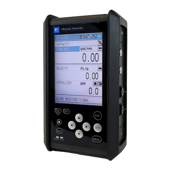
- Page 17 4. NAME AND EXPLANATION OF EACH PART Hand strap Printer Rubber Detector Display window Signal cable Strap Keyboard Stand Keyboard Display window Printer (option) Detector Signal cable INF-TN3FSC-E...
- Page 18 AI/AO (4 to 20mA DC analog I/O connector) 12V DC UP STREAM (power connector) (detector connector on upstream side) Put the caps on the power supply port and/or the DOWN STREAM AI/AO port when they are not used. (detector connector on downstream side) Right side LCD contrast adjusting knob...
- Page 19 Fig. 4-1 Layout of keys Table 4-1 Explanation of keys Key indication Description or lamp The keyed-in data, selected item, etc. will be set by pressing this key. Cancels any setting. Moves the cursor upward, increments set value, etc. (repeats if held down) Moves the cursor downward, decrements set value, etc.
- Page 20 4.3.1 Handling notice INF-TN3FSC-E...
- Page 21 SD memory card slot CAUTION CAUTION INF-TN3FSC-E...
- Page 22 (1) Types of recorded data INF-TN3FSC-E...
- Page 23 Root Site name VALVE_Open_20060703_163100.ini (File) (Folder) Log name Date Time VALVE_Open_20060703_163100.csv (File) Logger Log name Date Time VALVE_Open_20060705_183100.csv (File) Log name Date Time QUICK_20060704_163100.ini (File) Quick logger QUICK_20060703_163100.csv (File) Date Time Flow velocity distribution Vel_20060704_163100.csv (File) Data Time Vel_20060705_163100.csv (File) Date Time Hard copy...
- Page 24 Press the INF-TN3FSC-E...
-
Page 25: Power Supply
5. POWER SUPPLY Cord side connector Flow transmitter side connector white mark Power connector conversion cord Power cord AC power supply adapter AC power supply Notes: INF-TN3FSC-E... - Page 26 (3) Operating by AC power adapter for a prolonged time CAUTION INF-TN3FSC-E...
- Page 27 Language to be set is displayed. To select the language When the language is displayed (for about 8 sec.), press the ENT key, and the “Language Selection”screen appears. In the screen that is displayed, select Note: your desired language and press the ENT From the next step, the key.
- Page 28 CAUTION INF-TN3FSC-E...
- Page 29 6. WIRING To connect signal cables for FSSC, FSSD, FSSH, FSDP2, FSDP1, FSDP0 connector Printer Detector (option) Signal cable To connect signal cables for FSSE Conversion cord BNC connector Detector input Detector (the downstream side) Flow transmitter Detector input (the upstream side) Analog input/output cable FEED AO analog output 4 to 20mA DC...
- Page 30 Connection of analog input/output cable Red (+) AI/AO Note) Plug the 4 to 20mA connector (output) into AI/AO. AI ch1 − + Black (input) Indicator, Black recorder, controller, etc. Analog input/output cable Converter Code color Clip color Mark Black (BK) Red (R) Black White (W)
- Page 31 7. INPUT OF PIPING SPECIFICATIONS Display of pipe setup screen MENU Press the INF-TN3FSC-E...
- Page 32 Sets lining material Sets outer diameter of pipe Sets pipe material Sets lining thickness Sets pipe thickness Sets type of sensor Sets transmission voltage Sets sensor mounting method INF-TN3FSC-E...
- Page 33 Mounting dimension CAUTION INF-TN3FSC-E...
- Page 34 INF-TN3FSC-E...
- Page 35 [Reference] Description of character entry screen Select a character and press the Character entry field Character display Key for registering characters Key for deleting a character in the entry field in the entry field Cancel key for character entry. INF-TN3FSC-E...
- Page 36 Press the and the INF-TN3FSC-E...
- Page 37 screen Press the Press the Outer diameter of piping Perimeter of piping Outer diameter Perimeter Example) When the outer diameter of piping is 318.5 mm: INF-TN3FSC-E...
-
Page 38: Cast Iron
Press the Press the When “OTHERS” is selected: Example) When the piping material is cast iron: INF-TN3FSC-E... - Page 39 Press the Press the Lining and wall thickness of piping B : Lining A : Wall thickness thickness Example) When the wall thickness is 1.25 mm: INF-TN3FSC-E...
- Page 40 Press the Press the When “OTHERS” is selected: Example) When the lining material is mortar: INF-TN3FSC-E...
- Page 41 Press the Press the Example) When the lining thickness is 1.25 mm: INF-TN3FSC-E...
- Page 42 Press the Press the When “OTHERS” is selected: INF-TN3FSC-E...
- Page 43 Viscosity Remarks Press the Press the INF-TN3FSC-E...
- Page 44 V method Z method Press the (Except. Small sensor FSSD1) Press the Remarks INF-TN3FSC-E...
- Page 45 7.11 Kind of sensor Press the Press the Select the sensor by the Example) When kind of sensor is FSSD: INF-TN3FSC-E...
- Page 46 Press the Press the Example) When transmission voltage is set to “160Vpp”: Indicator INF-TN3FSC-E...
- Page 47 MENU MENU [Unit: mm] CARBON STELL 2.15 3.21 STAINLESS STEEL 1.87 DUCTILE IRON 2.15 3.69 PEEK 3.69 COPPER 3.82 PVDF 3.69 CAST IRON 2.98 ACRYLIC 2.90 ALUMINUM 1.99 3.69 INF-TN3FSC-E...
- Page 48 8. MOUNTING OF DETECTOR INF-TN3FSC-E...
- Page 49 or more or more D + 1200 or more D: Pipe diameter [mm] Space required for mounting detector Pipe may not be filled with liquid. Air-collecting Pipe may not be filled with liquid. Good Good Pump Air bubbles Pipe 45° Horizontal plane 45°...
- Page 50 Welded part Flange or welded Welded part INF-TN3FSC-E...
- Page 51 Selection of detector <Large/Mediam sensor> Detector Detector V method Z method <Small diameter sensor, small sensor or high-temperature sensor> Length of frame of each sensor Length of frame of each sensor Frame L: Mounting dimension V method Z method The dimension values of the Mounting method sensor attachment displayed on the SITE SETTING...
- Page 52 Type FSSC, FSSD, FSSH FSSE Mounting V method V method method Mounting Mounting dimensions Mounting dimensions dimensions Type FSSC, FSSD, FSSH FSSE Mounting Z method Z method method Mounting dimensions Mounting Mounting dimensions dimensions (3) Detector selection standards Inner diameter of piping ø (mm) Fluid Type temperature [°C]...
- Page 53 Detector Width Small outer 320 mm or more diameter FSSD1 Jute is wound Pipe Medium size (standard) sensor 540 mm or more FSSC, FSSD3 Large size sensor Mounting dimension (L) + 200 mm or more FSSE Width High temperature 530 mm or more FSSH INF-TN3FSC-E...
- Page 54 CAUTION Rail end INF-TN3FSC-E...
- Page 55 100mm (3.937 inch) Mounting dimension Before applying When applying After applying INF-TN3FSC-E...
- Page 56 Mounting on the pipe Example: Excessive turning element holder causes the rail end to come off the pipe. Example: Excessive turning element holder cause the resin pipe to deform Deformation of the pipe INF-TN3FSC-E...
- Page 57 Mounting Rail end Pipe Loosen the screw Rail end INF-TN3FSC-E...
- Page 58 Minimum radius to bend 100mm INF-TN3FSC-E...
- Page 59 CAUTION INF-TN3FSC-E...
- Page 60 INF-TN3FSC-E...
- Page 61 end and wrap it around the pipe and end and wrap it around the pipe and INF-TN3FSC-E...
- Page 62 Saddle Lock nut Element holdder BNC connector Cursor Mounting dimension (L) Scale Frame Transmitting surface CAUTION Element holder Cloth belt Cable Element holder CAUTION INF-TN3FSC-E...
- Page 63 Scale Saddle Element holder BNC connector Frame Lock nut Curser Guide rall for small size sensor (option) Sensor unit Mounting dimension (L) Silicone grease Transmitting surface Element holder CAUTION Front view Upper side of the marking line Back view Bottom side of the marking line INF-TN3FSC-E...
- Page 64 Cable Element holder CAUTION INF-TN3FSC-E...
- Page 65 Line drawn 100mm on gauge paper Align this edge. Draw line A. Draw a line along the edge. 200mm Straight line B 100mm INF-TN3FSC-E...
- Page 66 CAUTION Cover Cable clamp CAUTION Conversion cord INF-TN3FSC-E...
- Page 67 Signal cable Conversion cord BNC connector Fixing screw Guide plate Transmission direction mark Pipe Transmission surface Fastening spring Loosen this wire clip and pull the wire rope. Marked lines Sensor Pipe INF-TN3FSC-E...
- Page 68 (3) Mounting of sensor CAUTION CAUTION INF-TN3FSC-E...
- Page 69 Element holder BNC connecot Lock nut Saddle Cursor Mounting Scale dimension Frame High temperature Spatula grease Transmission unit Stainless belt Stainless belt CAUTION Element holder Cable INF-TN3FSC-E...
- Page 70 Sensor unit Lock nut BNC connector Element holder Saddle Cursor Frame Scale Guide rail for high temperature sensor Mounting dimension (L) High temperature Spatula grease Transmitting surface Element holder Front view Back view Upper side of Bottom side of the marking line the marking line INF-TN3FSC-E...
- Page 71 Element holder Cable INF-TN3FSC-E...
- Page 72 200 mm or D or larger Parallel About 100 mm INF-TN3FSC-E...
- Page 73 9. START MEASURING (3) Measurement mode (4) Analog input/output (1) Clock (2) SD memory card (5) Indicator (6) Battery (7) Site name (8) Quick logger Cursor (13) Switching measure- ment screen (10) Measure- (11) Unit of flow rate mernt kind Display 1 (10) Measure- mernt kind...
- Page 74 (1) Clock (2) Memory card (3) Measurement mode (5) Indicator (7) Site name INF-TN3FSC-E...
- Page 75 : Cannot be started (9) Status display is indicated at the (11) Flow rate and then press the INF-TN3FSC-E...
- Page 76 position and press the If you press the the currently displayed and press the INF-TN3FSC-E...
- Page 77 (15) Status display of total It allows you to start/stop the total process on and press Start and press the INF-TN3FSC-E...
- Page 78 Various function pages MENU MENU [Measure screen] [Menu screen] MENU SITE SETUP RANGE DATA LOGGER Condition settings for Setting of input and Saving of measured value measurement output range to memory, and display and output of data PRINTER SYSTEM SETUP MAINTENANCE Various outputs on printer Change of basic system...
- Page 79 on the page [Operation] Press the Reads out the contents of setting. Stores the contents of setting in memory. Deletes the contents of setting. INF-TN3FSC-E...
- Page 80 INF-TN3FSC-E...
- Page 81 [Operation] and press the CAUTION INF-TN3FSC-E...
- Page 82 Direction of selected unit Display Logger Printer Flow rate unit : The unit selected by the unit of output is used. Flow rate total : The unit selected by measurement screen is used. Temperature Thermal total [Operation] INF-TN3FSC-E...
- Page 83 Select the unit by the INF-TN3FSC-E...
- Page 84 [Operation] and then press the INF-TN3FSC-E...
- Page 85 Flow rate Time Response time [Operation] INF-TN3FSC-E...
- Page 86 This function enables you to set Calculation of output value Measured Set span value × + Set zero-point value = Output value value After correction Before correction Flow velocity Flow (%) Zero point shift Span shift [Operation] press the CAUTION INF-TN3FSC-E...
- Page 87 Output - 0.010m/s 0.010m/s Flow velocity [Operation] INF-TN3FSC-E...
- Page 88 [Operation] Press the and then press the CAUTION and the INF-TN3FSC-E...
- Page 89 Mode Description Instant total starts INF-TN3FSC-E...
- Page 90 Press the The total continues until the burnout INF-TN3FSC-E...
- Page 91 Site name Sets operation. Saved data capacity Free space Logger Saved logger data (The green displays under logging.) Quick logger Up to 100 items can be viewed by using the cursor. For 100 or more, check SD memory card directly by your PC. Kind of measurment data Logging name Operation mode...
- Page 92 Start button Measurement screen INF-TN3FSC-E...
- Page 93 : Logging : PM9:00 : AM4:00 : Logging : 21:00 : 04:00 INF-TN3FSC-E...
- Page 94 File type File name Remarks (Logging name)_(date)_(hour).ini Means logger start time and relevant logger (Logging name)_(date)_(hour).csv Press the INF-TN3FSC-E...
- Page 95 [Operation] Press the by the INF-TN3FSC-E...
- Page 96 Press the CAUTION INF-TN3FSC-E...
- Page 97 CAUTION INF-TN3FSC-E...
- Page 98 [Operation] INF-TN3FSC-E...
- Page 99 Mode Description Displays logging conditions. Cursor Graduation interval Data value at the position of cursor Data axis zoom bar (vertical axis). Time axis zoon bar (Horizontal axis). Kind of data Enlarging the graph (Displays kind of data displayed on the graph) Movement of data axis, time axis and...
- Page 100 Press Scroll bar Time Cursor Data File No. of logger data Name of logger data Starting time/date Ending time/date The number of logger data Kind of data (source) Unit of printing data INF-TN3FSC-E...
- Page 101 [Operation] INF-TN3FSC-E...
- Page 102 Select “START DATA POSI.” and press Change to 7 by the keys. Name and condition of selected logger data Select “STOP DATA POSI.” and press Change to 361 by the Total of logged data keys. Printing conditions of Select “CYCLE” and press logger data above Change to 00:10:00 by the keys.
- Page 103 Press the Press the Press the Select the display of date by the press the YYYY : Year MM : Month DD : Day INF-TN3FSC-E...
- Page 104 Setup contents CAUTION INF-TN3FSC-E...
- Page 105 [Operation] Press the INF-TN3FSC-E...
- Page 106 LCD POWER OFF LCD POWER OFF LCD ON LCD OFF LCD Power OFF Key operation [Operation] Press the INF-TN3FSC-E...
- Page 107 [Operation] Press the CAUTION INF-TN3FSC-E...
- Page 108 [Operation] Press the CAUTION CAUTION INF-TN3FSC-E...
- Page 109 [Operation] Press the press the CAUTION press the CAUTION INF-TN3FSC-E...
- Page 110 and calibration (Note) The connector should be connected to AI/AO. Black 4 to 20mA (Output) AI ch1 − + (Input) Indicator, Black recorder, regulator, etc. Analog input/output cord (page 20) 1 to 5V DC 1 point Press the INF-TN3FSC-E...
- Page 111 [Operation] Press the and press the INF-TN3FSC-E...
- Page 112 [Operation] CAUTION INPUT CH1 DEFINITION INPUT CH2 DEFINITION INF-TN3FSC-E...
- Page 113 Calibration procedure [Operation] Press the screen by the INF-TN3FSC-E...
- Page 114 Current Input Caribration procedure Input 4mA from external. Under calibration of 4mA Input 20mA from external. Under calibration of 20mA End of calibration After calibration, the “End of Calibration” message appears under the calibration button. CAUTION INF-TN3FSC-E...
- Page 115 Calibration procedure [Operation] Press the screen by the INF-TN3FSC-E...
- Page 116 Input 1V from external. Under calibration of 1V Input 5V from external. Under calibration of 5V End of calibration After calibration, the “End of Calibration” message appears under the calibration button. CAUTION INF-TN3FSC-E...
- Page 117 Calibration procedure [Operation] Press the Transition from 4 mA to 20 mA or vice versa. Adjust output to 4 mA Adjust output to 20mA with an ammeter and and press press “Output calibration” by “Output calibration” by pressing the key. pressing the key.
- Page 118 Flowmeter (Type: FSC) Consumed heat quantity q = K · Q · (T1–T2) Converter K : heat quantity AI/AO conversion factor (For heating K = 4.123, Temperature For cooling = 4.186) sensor T1: Fluid temperature (inlet) Converter Detector Temperature (type : FSS) sensor T2: Temperature of the heating Q: Flow rate of the...
- Page 119 INF-TN3FSC-E...
- Page 120 INF-TN3FSC-E...
- Page 121 or input voltage. Full scale 20mA or 5V Input conversion Input conversion = Input (%) / 100 × (Full scale – Base scale) + Base scale Base scale 4mA or 1V 100% Input Press the press the Press the INF-TN3FSC-E...
- Page 122 INF-TN3FSC-E...
- Page 123 Press the is displayed Output limit high Analog output Output limit high 200mA 20mA Flow rate Output limit low Reverse Forward Output limit low 100% Flow rate Single range: Output one way by 0 to 100% Bi-directional range: Also output back-flow by 0 to 100%. Output = Momentum flow rate ×100 When switching flow direction, Hysteresis / Full scale...
- Page 124 Press the Press the CAUTION INF-TN3FSC-E...
- Page 125 and press the Press the and press the INF-TN3FSC-E...
- Page 126 Press the INF-TN3FSC-E...
- Page 127 Press the Prints text data for selected unit in industrial value. Example of printout Prints data for selected unit in graph. Example of printout Prints selected list. Example of printout Displays the status of printer and performs test printing. Example of printout INF-TN3FSC-E...
- Page 128 Printing of graph Y axis Glancing piling interval Print cycle Measurement condition Selected type + Flow rate total – Flow rate total X axis Test print INF-TN3FSC-E...
- Page 129 Press the press the Press the CAUTION INF-TN3FSC-E...
- Page 130 Press the by the Press the Press the CAUTION INF-TN3FSC-E...
- Page 131 Show the contents of error display below INF-TN3FSC-E...
- Page 132 press the INF-TN3FSC-E...
- Page 133 and press the INF-TN3FSC-E...
- Page 134 press the Press the Scroll bar Press the Cursor Data INF-TN3FSC-E...
- Page 135 INF-TN3FSC-E...
- Page 136 Peak value of about 5528 Noise level to 6758 The receiving waveform is being inter- rupted. INF-TN3FSC-E...
- Page 137 screen and press the Display unit INF-TN3FSC-E...
- Page 138 Flow rate output Input data Initial value Tracking time Time CAUTION INF-TN3FSC-E...
- Page 139 INF-TN3FSC-E...
- Page 140 INF-TN3FSC-E...
- Page 141 press the Press the INF-TN3FSC-E...
- Page 142 Press the MENU INF-TN3FSC-E...
- Page 143 and press the Example) INF-TN3FSC-E...
- Page 144 Preparation Root UPDATE (Folder) (File) FSC_SYSM.bin (File) FSC_SPDM.bin CAUTION INF-TN3FSC-E...
- Page 145 Main unit type: FSC Wound with jute Piping L+200mm FSDP2, FSDP1 FSDP0 Screw INF-TN3FSC-E...
- Page 146 Absorber unit Sensor unit Flow direction Flow direction FSDP2, FSDP1 FSDP2, FSDP0 Screw INF-TN3FSC-E...
- Page 147 Match the edge of gauge paper with the line at 100mm about 100mm from one end of the pipe portion treated for detector mounting, and wind the gauge paper so that the line marked on the paper is parallel with the pipe axis (fix with tape not to allow deviation).
- Page 148 FSDP2, FSDP1 FSDP0 Screw Absorber unit Sensor unit FSDP2, FSDP1 FSDP0 Flow Flow direction direction INF-TN3FSC-E...
- Page 149 Screw Connect the detector and the converter unit INF-TN3FSC-E...
- Page 150 Preparation MENU INF-TN3FSC-E...
- Page 151 Pipe center Graduation Displays mean fluid velocity or flow rate. interval Status display in case of an error. See "10.8 Contents of errors in status display" in case of status display. Pipe inside wall Flow velocity Flow velocity Pipe inside wall distribution 1 distribution 2 Data of cursor position...
- Page 152 and press the INF-TN3FSC-E...
- Page 153 when the INF-TN3FSC-E...
- Page 154 <Maximum measurable flow velocity> <Maximum measurable flow rate> Unit: m/s Unit: m Diameter FSDP2 FSDP1 FSDP0 FSDP2 FSDP1 FSDP0 6.56 33.6 6.52 52.7 5.31 72.1 4.65 86.5 4.12 100A 3.69 7.25 125A 6.08 3.08 150A 5.20 2.63 200A 4.05 7.77 2.04 250A 3.30...
- Page 155 INF-TN3FSC-E...
- Page 156 INF-TN3FSC-E...
- Page 157 INF-TN3FSC-E...
- Page 158 INF-TN3FSC-E...
- Page 159 11. MAINTENANCE AND CHECKUP INF-TN3FSC-E...
- Page 160 INF-TN3FSC-E...
-
Page 161: Stainless Steel
Name Arrangement No. Battery Special type Li-ion battery ZZP*TK7N6384P1 (7.4V, 2500mAh)×2 Power Special type power adapter ZZP*TQ505735C4 adapter Power code Japan, North America:125V AC 2m ZZP*TK7N6621P1 Europe, Korea: 250V AC 2m ZZP*TK7N6608P1 China: 250V AC 2m ZZP*TK7N6609P1 Printer unit To be mounted on top of converter ZZP*TK4J2634C1 Thermal serial dot system (8 x 384 dot) Printer roll... - Page 162 12. ERROR AND REMEDY 12.1 Error in LCD Display Cause Remedy Status No display appears. No response is made to key input. Contact Fuji Electric Any particular key does not function or functions in a INF-TN3FSC-E...
- Page 163 State Cause nate the true cause as instructed Mount the sensors at the lowest INF-TN3FSC-E...
- Page 164 State Cause of air bubbles is the cause of this Mount the sensors in parallel INF-TN3FSC-E...
- Page 165 State Cause Select a different location of the cross section of pipe has a Measure in a place subject to INF-TN3FSC-E...
- Page 166 12.4 Error in analog output State Cause Output rises beyond INF-TN3FSC-E...
- Page 167 13. EXTERNAL COMMUNICATION SPECIFICATION Item Transmission scheme Half duplex Asynchronous Transmission rate 500kBPS Parity Odd parity Start/stop bit 1 bit Data length 8 bits Station Number of connectable units 1 unit Transmission code Hexadecimal value (MODBUS RTU mode) Error detection CRC-16 Echo back None...
- Page 168 14. HOW TO USE PRINTER Front view (connecter) INF-TN3FSC-E...
- Page 169 INF-TN3FSC-E...
- Page 170 CAUTION Don’t pull the sheet opposite the INF-TN3FSC-E...
- Page 171 15. REPLACEMENT OF BUILT-IN BATTERY INF-TN3FSC-E...
- Page 172 CAUTION INF-TN3FSC-E...
- Page 173 16. APPENDIX 16.1 Piping data (1) Stainless steel pipe for pipe arrangement (JIS G3459-2012) Thickness Nominal Outer Schedule Schedule Schedule Schedule Schedule Schedule Schedule diameter diameter Thickness Thickness Thickness Thickness Thickness Thickness Thickness 17.3 1.65 – – 21.7 1.65 – 27.2 1.65 –...
- Page 174 (4) Polyethlene pipe for general use (JIS K6761-1998) (5) PVC pipe for water (JIS K6742-2007) VP: PVC pipe 1st type 2nd type HIVP: anti-shock PVC pipe etc. Outer Nominal (Soft pipe) (Hard pipe) diameter diameter Thickness Thickness Nominal Outer Pipe (mm) (mm) (mm)
- Page 175 (10) Steel pipe coated for city water STW (JIS G3443-1:2007) Symbol for type STW 400 Nominal Outer STW 290 STW 370 Nominal thickness diameter diameter (mm) Thickness Thickness Thickness Thickness (mm) (mm) (mm) (mm) 89.1 – – 114.3 – – 139.8 –...
-
Page 176: Ductile Iron
(13) Arc welded large-diameter stainless steel pipe for pipe arrangement SUS (JIS G3468-2011) Nominal thickness Nominal diameter Outer Schedule Schedule Schedule Schedule diameter (mm) Thickness Thickness Thickness Thickness 165.2 216.3 267.4 318.5 10.3 355.6 11.1 406.4 12.7 457.2 14.3 508.0 15.1 558.8 15.9... - Page 177 (19) Cast iron pipe for waste water(JIS G5525-1975) Mechanical type Insertion type 1st type pipe 2nd type pipe RJ pipe Nominal Straight/deformed Straight pipe Deformed pipe Straight pipe Deformed pipe diameter pipe Outer Pipe Outer Pipe Outer Pipe Outer Pipe Outer Pipe diameter...
- Page 178 (20) PVDF-HP (21) Heat-resistant hard vinyl chloride pipe PVC-C (JIS K6776:2007) SDR33 SDR21 SDR17 Outer S16 PN10 S10 PN16 S8 PN20 Nominal Thickness Weight diameter Outer diameter (mm) (kg/m) Thickness Thickness Thickness (mm) diameter (mm) (mm) (mm) 18.0 0.180 (mm) 22.0 0.265 26.0...
-
Page 179: Aluminum
(24) Velocity of sound and density of various water (0 to 100°C) liquids Name of liquid T°C g/cm Vm/s T°C Vm/s T°C Vm/s T°C Vm/s T°C Vm/s 1402.74 Acetone 0.7905 1190 1407.71 1499.64 1543.93 1555.40 Aniline 1.0216 1659 1412.57 1502.20 1544.95 1555.31 Alcohol... - Page 180 Start screen Language selection Japanese English German French Spanish Chinese Measurement screen (numeric value) Quick logger 1st line Measurement kind Unit of flow rate Changing decimal position Total reset Total start/ stop 2nd line Same as above 3rd line Same as above Status display Measurement screen (graph) Quick logger...
- Page 181 Range Input range Base scale Full scale Base scale Full scale Output range Range Kind RANGE TYPE Full scale Output limit low Output limit high Error System setup Basic Settup Clock System unit LCD power off Definition of PRINT key Measurement method Memory initialize Analog input/output...
- Page 182 Measuring objects Flow transmitter (Type: FSC) Measurement fluid: Power supply: Built-in battery or AC power adapter Uniform liquid in which ultrasonic Built-in battery: Exclusive lithium button battery waves can propagate. (5000m Ah) Turbidity of fluid: 10000 mg/L or less Continuous operation time, approx. 12 State of fluid: Well-developed turbulent or laminar hours (without printer, back light OFF,...
- Page 183 SD memory card: Used for data logger function and Functions recording screen data. Display language: Selectable from Japanese, English, Available up to 8GB (Option256MB) German, French, Spanish or Chinese Compliant media (switchable by key operation). SD memory card: speed class 2, 4, 6 Clock display function: SDHC memory card: speed class 4, 6 Time (year, month, day, hour, minute)
- Page 184 Computation function of consumed heat quantity (calorie): Flow velocity profile measurement (option): This function calculates the heat Flow velocity profile may be observed quantity received and sent with liquid in real time using the exclusive detec- (water) in cooling and heating. tor (option).
- Page 185 EU Directive Compliance FLOW VELOCITY PROFILE DISPLAY FUNCTION LVD (2014/35/EU) (OPTION) EN 61010-1 EMC (2014/30/EU) Pulse Doppler method enables the analysis and display of EN 61326-1 (Table 2) the flow velocity profile in real time. The results can be used EN 55011 (Group 1 Class A) to decide the appropriate measurement location, for flow EN 61000-3-2 (Class A)
- Page 186 Air bubbles 2D/3 1D/3 Deposit of sludge INF-TN3FSC-E...
- Page 187 12 12 Advanced ABM system Existing system 0.03 0.02 0.02 [vol.%] Flow velocity [m/s] (Note) The flowmeter indicates volume flow containing air bubbles. * Example of measured data Negative pressure Upper Sensor Sensor Lower INF-TN3FSC-E...
- Page 188 Flow velocity Accuracy Inside diameter ø ø of measured flow ø ø of measured flow ø ø of measured flow ø ø of measured flow *1: Example of calculation Error at 2m/s Error at 1m/s (1) Piping size Flow error +1mm Inside diameter Flow error...
- Page 189 (3) Flow in piping is deviated Typical characteristics (Piping: SUS, 150A, FS: 1.3m/s) Flow error % of rate Water temperature (°C) * Example of measurement INF-TN3FSC-E...
- Page 190 Others 1. Life span of LCD 2. Printer roll sheet INF-TN3FSC-E...
- Page 191 Table 16-1 Data types Maximum number Number of places Kind Name Sign of places of integer Unit of decimal section VELOCITY VELOCITY 3 places 3 places FLOW RATE FLOW RATE 12 places 4 places Flow unit FLOW RATE (%) FLOW RATE (%) 3 places 3 places +TOTALIZER...
- Page 192 Item Contents PRODUCT Product name ("ULTRASONIC FLOWMETER VERSION TIME Logger start date and hour CYCLE Logger acquisition period (sec) Item Contents FILE File name of logger data INDEXx Offset (bytes) to (date and hour) data in the logger data is added sequentially beginning from 1 as indicated below.
- Page 193 Table 16-2 Line Contents Line 1 B and subsequent Names of logged types for the quantity, including RAS. ASCII characters show names. See "16.5.1 Types of measured data to be logged". Line 2 B and subsequent Units of logged types for the quantity. ASCII characters show units.
- Page 194 Table 16-3 Line Contents Describes "<Measurement result>". B and subsequent Describes "Channel number". Channel number 126 to 1, 1 to 126 in case of connection of sensor U Line 2 C and subsequent 1 to 126, 126 to 1 in case of connection of sensor D 1 to 126, 126 to 1 to IT row in case of connection of sensor U/D Describes "<F.RATE/VEL.VALUE>".
- Page 195 Instrumentation & Sensors Planning Dept. 1, Fuji-machi, Hino-city, Tokyo 191-8502, Japan http://www.fujielectric.com Phone: +81-42-514-8930 Fax: +81-42-583-8275 http://www.fujielectric.com/products/instruments/...
Need help?
Do you have a question about the FSC-1 and is the answer not in the manual?
Questions and answers