Table of Contents
Advertisement
Quick Links
Advertisement
Table of Contents

Related Manuals for Fuji Electric FE ZSS


Summary of Contents for Fuji Electric FE ZSS
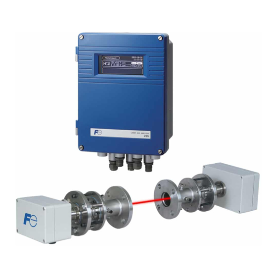
- Page 1 Instruction Manual CROSS STACK LASER GAS ANALYZER TYPE: ZSS INZ-TN1ZSS-E...
-
Page 2: Preface
PREFACE We thank you very much for purchasing Fuji Electric’s cross-stack laser gas analyzer (Type: ZSS). • First read this instruction manual carefully until an adequate understanding is acquired. Then proceed to installation, operation and maintenance of the laser gas analyzer. Improper handling may result in an accident or a failure. -
Page 3: Caution On Safety
CAUTION ON SAFETY First of all, read this “Caution on safety” carefully, and then use the particle counter in the correct way. The following items are important for safe operation and must be fully observed. These safety precautions are ranked in 2 levels; “DANGER” and “CAUTION.” ANGER If operation is incorrect, a dangerous situation may occur, resulting in death or serious injury. - Page 4 Caution on Wiring AUTION • Be sure to connect a ground wire securely to the specified place by per- forming class D grounding work. Otherwise electric shock or malfunction may result. • If the power supply voltage exceeds the rating, electric shock or damage to the instrument may result.
- Page 5 Caution on operation and use ANGER • When handling the standard gas such as calibration gas, read the instruc- tion manual of the standard gas carefully, and use the gas correctly. • When toxic fumes, corrosive gas or inert gas is used as calibration gas, be sure that the position of the air ventilation or exhaust port is suitable.
- Page 6 AUTION • If the cause of any fault cannot be determined despite reference to the in- struction manual, be sure to contact your dealer or Fuji Electric’s techni- cian in charge of adjustment. If the instrument is disassembled carelessly, you may get an electric shock or injury.
- Page 7 Label positions R TING L BEL SECTION − R TING L BEL Made in Japan CROSS STACK LASER GAS ANALYZER TYPE OUTPUT DC POWER AC100‑240V 50/60Hz 70VA SER. NO. Fuji Electric Systems Co.,Ltd. SECTION B − Receiver box R TING L BEL R TING L BEL Section C C' C UTION L BEL L SER PRODUCT L BEL C UTION L BEL L SER PRODUCT L BEL Section...
- Page 8 CONT OL UNIT COVE CE TIFICATION LABEL ATING LABEL FUJI ELECTRIC SYSTEMS CO.,LTD. Complies with 21 CFR 1040.10 and 1040.11 except for deviations pursuant to Laser Noitce No.50, dated July 26,2001 1,Fuji−machi,Hino−city,Tokyo 191−8502,Japan MANUFACTURED:FUJI ELECTRIC INSTRUMENTS CO.,LTD. A A OW Made in Japan CROSS STACK LASER GAS ANALYZER TYPE OUTPUT DC POWER AC100‑240V 50/60Hz 70VA SER. NO. Fuji Electric Systems Co.,Ltd. LASER GAS ANALYZER A A OW FIGU E Control unit - vii - INZ-TN1ZSS-E...
-
Page 9: Table Of Contents
Contents PREFACE................................I CAUTION ON SAFETY..........................II 1. GENERAL ..............................1 1.1 General..............................1 1.2 Handling of product and operating precautions ..................1 2. CHECKING DELIVERED ITEMS......................2 2.1 Delivered articles (products and standard accessories)................2 3. NAME AND EXPLANATION OF EACH PART ..................4 3.1 Overall composition.......................... - Page 10 5.3.1.8 Basic Operation .........................29 5.3.1.9 Alarm types..........................32 6. ZERO CALIBRATION AND SETTING ....................34 6.1 Zero calibration............................34 6.1.1 Preparation ............................34 6.1.2 Zero calibration ..........................36 6.2 Span calibration ............................37 6.2.1 Preparation ............................37 6.2.2 Span calibration..........................38 6.3 Alarm setting............................39 6.3.1 Alarm value ON/OFF........................39 6.3.2 Setting of alarm value ........................40 6.3.3 Analog output / alarm record......................42 6.3.4 Hysteresis setting ..........................43...
-
Page 11: General
1. GENERAL 1.1 General Cross-stack laser gas analyzer (ZSS) provides continuous measurement of HCl in-flue gas incineration and density of denitration equipment within a short response time. The cross-stack configuration eliminates the need for transfer of the preparation measurement gas to the analyzer for proper measurement. Dust resistant construction enables installation upstream of bug filter units and the application for which in- jection volume of calcium hydroxide is controlled while measuring HCl concentration. -
Page 12: Checking Delivered Items
2. CHECKING DELIVERED ITEMS Upon receiving the recorder unit, check if the correct quantity of the accessories are supplied. Separately supplied document are given first priority. When you have purchased or want to purchase spare parts for 1-year operation or a list of calibration/installation fixtures, refer to 2-2 and 2-3 of “Appendix 2”at the end of this Manual. - Page 13 Control unit eceiver box Transmitter box Carton box Cable between control unit and receiver unit, eceiver/Transmitter unit cable Calibration gas cell Standard accessories Hexagonal socket bolt Angle adjustment unit - 3 - INZ-TN1ZSS-E...
-
Page 14: Name And Explanation Of Each Part
3. NAME AND EXPLANATION OF EACH PART 3.1 Overall composition The analyzer consists of 3 units; “Transmitter unit” to transmit the laser, “Receiver unit” to receive light, and “Control unit” to display and output signals. 7) Mounting 1) Receiver box 6) Purging gas inlet Flange pipe to 2) Transmitter box... - Page 15 Name Description Receiver box A photodiode to receive light and a board are built-in. Transmitter box Laser light source, peltier to control the temperature of laser and a board are built-in. Adjustment probe for received Terminal which checks the intensity of received light volume when light light quantity axis adjustment is performed.
-
Page 16: Input/Output Terminal Of Control Unit
3.2 Input/output terminal of control unit Each input/output signal from the analyzer is connected to board terminal of the control unit. There are 2 types of the input/output terminal boards. Refer to the same figure that has the same terminal allocation as the product you received. - Page 17 AI terminal 1 AI1+ Analog input 1 (AI1) 2 AI1– 3 AI2+ Analog input 2 (AI2) 4 AI2– 5 AI3+ Analog input 3 (AI3) 6 AI3– 7 AI4+ Analog input 4 (AI4) 8 AI4– AI expansion board 9 AI5+ required Analog input 5 (AI5) 10 AI5–...
- Page 18 (2) Input / output terminal 2 xternal power AO terminal / AI terminal supply connection terminal / DI/DO terminal External power supply connection terminal 1 100 to 240V AC (50/60Hz) (L) 2 100 to 240V AC (50/60Hz) (N) 3 FG AO terminal Screw diameter : M2 1 AO1+...
- Page 19 AI terminal Screw diameter : M2 3 AI1+ 23 AI4+ Analog input 4 Analog input 1 4 AI1– 24 AI4– (AI expansion board repuired) 5 AI2+ 25 AI5+ Analog input 5 Analog input 2 6 AI2– 26 AI5– (AI expansion board repuired) 7 AI3+ Analog input 3 27 AI6+...
-
Page 20: Mounting Method
4. MOUNTING METHOD ANGER This analyzer is not explosion-proof. Do not use it in an atmosphere of ex- plosive gas. Otherwise, it can result in serious accidents such as explosion, fire, etc. AUTION The analyzer should be installed in a place conforming with the installa- tion requirements noted in this instruction manual. -
Page 21: Installation Conditions
4.1 Installation conditions 4.1.1 Installation conditions of receiver unit and transmitter unit 4.1.1 Installation conditions of receiver unit and transmitter unit Select a location that meets the following conditions. Ambient temperature : A place where the temperature is within -20 to 55°C and there is no sudden temperature change. -
Page 22: Mounting Dimensions Of Receiver Unit And Transmitter Unit
4.2 Mounting dimensions of receiver unit and transmitter unit Mount the receiver unit and the transmitter unit in a place which has ample free space for maintenance and check as in the figure below (Fig. 4 - 1). Stack a: Inner diameter of 50mm or more b: 20 to 70mm (*1) c: Approximately 200 to 250mm (*2) d: 400mm or more (*3) -
Page 23: Mounting Range Of Companion Flange
4.3 Mounting range of companion flange (in factory range) Mount the companion flange so that it satisfies the conditions of the following figure (Fig. 4 - 2). If the con- ditions below are not satisfied, light cannot be received even if the light axis adjustment is performed by the angle adjustment unit. -
Page 24: Installation Procedure
4.5 Installation procedure Install equipments, referring to the following procedure. Item Page Check that the installation location for each equipment satisfies the contents in “4.1 P.11 Installation conditions”. ↓ Check that the installation location for the receiver unit and the transmitter unit satisfies P.12 the contents in “4.2 Mounting dimensions of receiver unit and transmitter unit”. -
Page 25: Checking Received Light Quantity
(14) Adjust the light quantity so that the light quantity value at the receiver unit becomes the P.21 neighborhood of the value recorded in (7). If the angle is adjusted with the furnace oper- ated, it may not become the neighborhood of the light quantity value in (7) due to the effect of dust, etc. -
Page 26: Angle Adjustment
4.7 Angle adjustment ellows Anchor nut Fixing bolt Optical axis adjusting tool (laser pointer) A flange flange Fig. 4-4 4.7.1 How to operate the angle adjustment unit (1) When you tighten the B flange Turn the fixing bolt and the anchor nut clockwise at the same time. If it is difficult to turn them, slightly loosen the anchor nut first. -
Page 27: Adjustment Procedure
4.7.2 Adjustment procedure 4.7.2.1 When an optical axis adjusting tool (laser pointer) is used AUTION Do not watch the laser pointer beam directly with the optical measuring device. Otherwise, it may cause serious damage to your eyes. (1) When A and B flanges shown in Fig. 4 - 4 are extremely tilted, adjust them in a flat place so that they are parallel to each other. -
Page 28: Piping System Diagram
4.8 Piping system diagram Copper or SUS pipe (outside product) Instrumentation air line joint (outside product) Flow meter 8/6 Teflon tube Filter regulator (outside product) Flow meter 20 to 00L/min Instrumentation air inlet With bolt and nut Purging gas inlet Mist (M 6×55) (with bell-and-spigot... -
Page 29: Wiring Connection
4.10 Wiring connection 4.10.1 Connecting Receiver / Transmitter cable The receiver unit and the transmitter unit are connected with the “Receiver/Transmitter cable”. Both ends of it are fitted with a female 16-pin connector (waterproof type). The connector has no polarity. Fix the receiver/transmitter unit to the stack, etc. -
Page 30: Connecting Cable Between Receiver Unit And Control Unit
4.10.2 Connecting cable between receiver unit and control unit The receiver unit and the control unit are connected with the “Cable between control unit and receiver unit”. Both ends of it are fitted with a female 10-pin connector (waterproof type). The connector has no polarity. Perform wiring in the way that the cable between receiver unit and control unit is not pulled. -
Page 31: Adjustment Of Light Quantity
4.11 Adjustment of light quantity AUTION • Do not look into the transmitter unit or direct the laser beam to the eyes of people while the power is turned ON. Otherwise, the laser beam may damage cornea of the eye. •... -
Page 32: Adjustment Of Fine Adjustment Screw
4.12 Adjustment of fine adjustment screw (standard accessory) This screw is used for adjustment when the light path length in the stack is long and when the quantity of light misses too much at the time of retightening in the procedure in “4.11 Adjustment of light quantity”. When each retightening is finished, perform fine adjustment by pressing with this screw. -
Page 33: Connecting Analog Input/Output
When noise source is in the vicinity Avoid installing this analyzer near an electrical ap- ount the varistor paratus which produces power source noise. (Such To power supply near the noise source as high frequency furnace, electric welder, etc.) If the analyzer must be used near such equipment, a Varistor separate power line should be used for avoiding... -
Page 34: Explanation Of Operation Panel And Screen
5. EXPLANATION OF OPERATION PANEL AND SCREEN 5.1 Name and description of operation panel isplay area LASER GAS ANALYZER MODE (1) ode key (3) Up key (5) Side key (2) Escape key (4) Down key (6) Entry key Name Description of functions Name Description of functions (1) Mode key... -
Page 35: Screen Configuration
5.2 Screen configuration Measurement Menu Zero Calibration Span Calibration Alarm Log Output Hold Parameter Setting AO Select Alarm Setting Display/Output 1 Input Signal Password Component (Select each function screen by and press ach Alarm Setting Display/Output 2 5.3 Outline of screen 5.3.1.1 “Measurement”... -
Page 36: Name (Functions)
5.3.1.2 Name (functions) (1) Measurable component ········ Displays the gas component to be measured in element symbol. (2) Concentration value ········ Displays measured value of concentration. (3) Unit ········ Displays the unit of concentration such as ppm, vol%, etc. (4) Instantaneous ········... -
Page 37: Menu" Screen
5.3.1.4 “Menu” screen 2006-04-01 Menu 12:00:00 Zero Calibration Parameter Setting Span Calibration Display/Output Alarm Log Input Signal Alarm Setting AO Select Output Hold Password ***** Press the key while the “Measurement” screen is displayed, and the “Menu” screen appears. (It does not appear when pressing the key while other screen is displayed. -
Page 38: Alarm Record" Screen
5.3.1.6 “Alarm Record” screen 2006-4-1 Alarm Record 12:00:00 Date Alarm Day Repair Over H-Limit 1 04/01 13:23 LD Temp. Error 03/29 11:01 03:23 Select Delete All Delete The screen displays the alarm record occurred in the past. The ten newest errors are logged. The oldest error will be deleted one by one every time a new alarm occurs. -
Page 39: Basic Operation
5.3.1.8 Basic Operation Moving the cursor 2006-4-1 Alarm Record 12:00:00 Date Alarm Day Repair Over H -Limit 1 04 / 01 11:23 HC ℓ LD Temp. Error 03 / 29 23:14 03:23 HC ℓ 03 / 25 15:23 Press. AI Under 13:28 03 /... - Page 40 Selected alarm deletion 2006-4-1 Alarm Record 12:00:00 Date Alarm Day Repair Over H -Limit 1 04 / 01 11:23 HC ℓ 03 / 29 23:14 LD Temp. Error 03:23 HC ℓ Press. AI Under 03 / 25 15:23 13:28 Low Air Purge 03 /...
- Page 41 All alarms deletion 2006-4-1 Alarm Record 12:00:00 Date Alarm Day Repair Over H -Limit 1 04 / 01 11:23 HC ℓ 03 / 29 23:14 LD Temp. Error 03:23 HC ℓ Press. AI Under 03 / 25 15:23 13:28 Low Air Purge 03 /...
-
Page 42: Alarm Types
5.3.1.9 Alarm types Following types of alarm are displayed. Alarm display Alarm contents Probable causes LD Failure Laser is faulty • Failure caused by laser durability LD Temp. Error Peltier which is cooling the laser • Peltier failure cannot control the set temperature. •... - Page 43 Alarm display Alarm contents Probable causes • Air purge pressure is lower than alarm Low Air Purge It is reported when purge pressure lower than the value set as alarms setting or the analyzer is not purged. on the “AO Select” screen. •...
-
Page 44: Zero Calibration And Setting
6. ZERO CALIBRATION AND SETTING 6.1 Zero calibration Select “Zero Calibration” from the “Menu” screen and press the key. 2006-04-01 2007-4-1 Menu Zero Calibration 12:00:00 12:00:00 Component HC ℓ Zero Calibration Parameter Setting Cell Length 1000 Span Calibration Display/Output Cal.Gas Value 0000 Alarm Log Input Signal... - Page 45 tack Receiver box Transmitter box (3) Mount the removed receiver box and transmitter box using the hexagonal bolt. (4) Provide the receiver/transmitter cable (for calibration) or the cable between control unit and receiver unit (for calibration). (5) Wiring should be performed as following figure. exagonal bolt exagonal bolt Calibration gas cell...
-
Page 46: Zero Calibration
(6) Mount the Rc1/4 joint to the calibration gas cell, and connect one side to the standard gas cylinder (N (7) When the pipe is connected as shown below, allow the gas to flow. (8) Flow of sampling gas should be 1.5L/min. (9) When you mount thermometer and pressure gauge as shown below, connect output of 4 to 20mA DC to analog input terminal of the control unit, referring to “3.2 Input/output terminal of control unit”. -
Page 47: Span Calibration
(11) “ZeroCal.Start” blinks for about 30 seconds. (12) When the calibration is completed, the cursor moves to “Cal.Finish”, and the current date is displayed at “LastCal.Day”. 6.2 Span calibration Select the “Span Calibration” from the “Menu” screen and press the key. -
Page 48: Span Calibration
6.2.2 Span calibration (1) If the power is OFF, turn it ON. (2) Check if the flow of span gas is approximately 1.5L/min. (3) Display the “Span Calibration” screen. (4) Point the to “Component”, and press the key. (5) Press the key or the key to select the measured gas component to be span-calibrated. -
Page 49: Alarm Setting
6.3 Alarm setting Select “Alarm Setting” from the “Menu” screen, and press the key. On the “Alarm Setting Gas” screen, select the measurable component by moving the with the key and the key. Press the key after measurable component is selected. “Alarm Setting” screen is displayed. Alarm Setting Gas Alarm Setting Range1... -
Page 50: Setting Of Alarm Value
Alarm Setting 50.00 Range1 H - Limit Range2 30.00 10.00 Range1 L-Limit 00.00 Range2 Hysteresis Select “ON” or “OFF” by the key or the Analog Output Range2 H- Limit Alarm Record key, and press the key. Alarm Setting 50.00 Range1 H - Limit 30.00 Range2... - Page 51 Alarm Setting 50.00 Range1 H - Limit 30.00 Range2 10.00 Range1 L-Limit Range2 00.00 Hysteresis Select “ON” by the key or the key, Analog Output Range2 H-Limit and press the key. Alarm Record Alarm Setting 50.00 Range1 H - Limit Range2 30.00 10.00...
-
Page 52: Analog Output / Alarm Record
Note Set the value so that H-Limit is larger than L-Limit, and that (H-Limit – L-Limit) is larger than hysteresis width. 6.3.3 Analog output / alarm record Set the recording range of the external alarm output such as analog output or the alarm record. Setting range can be selected from “H-Limit”, “L-Limit”... -
Page 53: Hysteresis Setting
Alarm Setting 50.00 Range1 H - Limit Range2 30.00 10.00 Range1 L-Limit 00.00 Range2 Hysteresis Analog Output Range1 H-Limit Alarm Record Explanation of alarm range Range1 H-Limit : Alarm output is provided only when a value exceeds the Range1 H-Limit. Range1 L-Limit : Alarm output is provided only when a value is lower than Range1 L-Limit. -
Page 54: Output Hold
Alarm Setting 50.00 Range1 H - Limit 30.00 Range2 10.00 Range1 L-Limit Range2 00.00 Hysteresis Analog Output Range1 H- Limit Alarm Record Setting Range 0 to 20% FS %FS: Indicates the rate for which the range width of each component is regarded as 100%. Hysteresis mode (in case of H-Limit) Alarm output is turned ON when the value exceeds the H-Limit. -
Page 55: Output Hold
6.4.1 Output hold Set output hold to “Last Meas.” or “Pre-set” to hold analog output. (Indication value on the screen is not held.) 2007-4-1 Output Hold 12:00:00 HC ℓ Point the to the measurable component to hold output by the key or the key, and press the... - Page 56 2007-4-1 Output Hold 12:00:00 HC ℓ Pre-set Setting Range “Last Meas.” : Holds the value for which “Last Meas.” is determined by the key. “Pre-set” : Holds the %FS value for which range is currently validated. Previous set value is kept held even if the range is switched during the hold.
-
Page 57: Remote Hold (Di3 Terminal)
6.4.2 Remote hold (DI3 terminal) Output hold can be performed by remote according to the external contact input (DI3 terminal, option). The value to hold output is “Last Meas.” only. 2.0s or more 2.0s or more 2.0s or more Short-circuit Remote hold signal Open 2.0s... -
Page 58: Setting Of Stack Lengths
Select the “Parameter Setting” from the “Menu” screen, and press the key. 2006-04-01 2007- 4 -1 Menu Parameter Setting 12:00:00 12:00:00 Parameter Setting Zero Calibration Path lengths 01000 Span Calibration Display/Output Average Period Min. Alarm Log Input Signal Reset Avg.Gas HC ℓ... -
Page 59: Setting Of Moving Average Time
2007-4-1 Parameter Setting 12:00:00 Path lengths 1000 Average Period Min. Reset Avg.Gas HC ℓ Change the numeric value by the key or Key Lock key, and move the digits by the Disp.Off Min. key. Press the key to validate the set input Date/Time 07 /... -
Page 60: Average Value Reset
6.5.3 Average value reset When the indication value and output value are set to the average value in the “6.6.1 Setting of instantane- ous/average value”, reset the average value to clear the measurement value and the O conversion value. When the indication value and the output value are set to the instantaneous value, nothing is changed even if average value is reset. -
Page 61: Key Lock
Remote average value reset (DI1 terminal) Apply rectangular waveform voltage (pulse width: 2.0 sec or more, pulse interval: 2.0 sec or more) to the input terminal of remote average value reset (DI1 terminal, option) to reset the average value. 2.0s or more Short-circuit Open Remote hold signal... -
Page 62: Setting Of Backlight Off
6.5.5 Setting of backlight OFF Automatic OFF setting of the backlight of the LCD unit can be made. If the specified time elapses since the measurement screen has been resumed, the backlight is automatically turned off. Press any key to reset backlight OFF. Setting range of the light off time is from 1 to 60 minutes. -
Page 63: Time Setting
6.5.6 Time setting Time setting can be made. 2007-4-1 Parameter Setting 12:00:00 Path lengths 01000 Average Period Min. Reset Avg.Gas HC ℓ Key Lock Disp.Off Point the to “Date/Time” by the or the Min. Date/Time 07 / 01 / 01 00:00:00 key, and press the key. -
Page 64: Display/Ao Setting
6.6 Display/AO setting Make a setting of “Inst./Avg.” or “Wet/Dry” which displays the measurement value or its external output value displayed on the “Measurement” screen. In case of 2 range specification, range setting is performed. Explanation of setting items “Inst./Avg.” : Make a setting of “instantaneous value”... -
Page 65: Wet/Dry Setting
Input switching of the remote instantaneous/average value (DI2 terminal) Apply rectangular waveform (pulse width: 2.0 sec or more, pulse interval: 2.0 sec or more) to the input terminal of remote average value to switch the instantaneous value and the average value. If the previous measured value is set as instantaneous value, and O correction value is set as average value, the previous measured value becomes the average value, and the O... - Page 66 Input switching of the remote range (DI4 terminal) Apply rectangular waveform (pulse width: 2.0 sec or more, pulse interval: 2.0 sec or more) to the remote range input terminal (DI4 terminal, option), and Range 1 and Range 2 are switched. 2.0s or more 2.0s or more 2.0s or more...
- Page 67 2007-4-1 Display/AOSetting 12:00:00 Inst. Range Control Avg. Range1 0 ~ 50.0 ppm Avg. Remote HCℓ Range2 0 ~ 1000ppm Range1 0 ~ 50.0 ppm Inst. HC ℓ Range2 0 ~ 1000ppm Select “Wet” or “Dry” by the key or the key.
-
Page 68: Analog Input
6.7 Analog input Makes a setting of the analog input related to the measured gas conditions such as gas temperature. Input the sensor signal to the analog input terminal of the control unit, and the measured gas conditions can be cali- brated. - Page 69 2007-4-1 Analog Input 12:00:00 Fixed 20mA GasPress.(kPa) Fixed 00.00 00.00 10.00 Select the channel (CH1 or CH2) connected to AI Gas Temp.(℃) Fixed 0027 0100 1000 terminal by the key or the key (se- Gas Flow(m/s) Fixed 02.00 00.00 20.00 Fixed 20.00 00.00...
-
Page 70: Setting Of Analog Input (Fixed Value)
6.7.2 Setting of analog input (fixed value) (in case of H Sets the fixed value to perform the calibration when the value for which the measured gas condition do not change, or the sensors to calibrate are not provided, or the number of calibration input terminals is insuffi- cient. -
Page 71: Setting Of Air Purge Pressure
2007-4-1 Analog Input 12:00:00 Fixed 20mA GasPress.(kPa) Fixed 00.00 00.00 10.00 Gas Temp.(℃) 0027 0000 0500 CH1 Gas Flow(m/s) Fixed 02.00 00.00 20.00 Fixed 20.00 00.00 21.00 O2 (vol%) H2O Fixed 020.0 000.0 100.0 (vol%) The same procedure can be implemented as for Alarm 20mA pressure gauge, thermometer or oxygen analyzer... -
Page 72: Selecting Analog Output
2007-4-1 Analog Input 12:00:00 Fixed 20mA GasPress.(kPa) Fixed 00.00 00.00 10.00 Gas Temp.(℃) 0027 0000 0500 CH1 Enter the purge pressure value to output alarm. Gas Flow(m/s) Fixed 02.00 00.00 20.00 Change the numeric value by the key or Fixed 20.00 00.00 21.00... -
Page 73: Setting Of Analog Output
6.8.1 Setting of analog output When the measurable component is 1, “Component” or “No” can be selected. When there is O conversion output, “O Conversion” is also selectable. 2007-4-1 Analog Output 12:00:00 Analog Output 1(AO1) Analog Output 2 (AO2) Select the analog terminal to be output by the or the key. -
Page 74: Maintenance
7. MAINTENANCE 7.1 Maintenance list To maintain the desired accuracy, we recommend you to perform periodical maintenance and inspection, referring to Table 7 - 1. Table 7-1 Maintenance cycle Items 6 months 1 year Light axis adjustment ○ Replacement of packing ○... -
Page 75: Zero Calibration
7.3 Zero calibration Refer to “6.1 Zero calibration”. 7.4 Span calibration Refer to “6.2 Span calibration”. 7.5 Replacement of packing Replace the packing, referring to the following figure. Replace the receiver packing and silicon packing C every two years. eceiver unit Transmitter unit Silicon packing A O-ring... -
Page 76: Troubleshooting
8. TROUBLESHOOTING (1) “Low Light Transmission” alarm is occurred. → 1) When the light axis is adjusted, do the gas temperature and the temperature differ from each other too much? → Yes (The stack might have been deformed by the temperature, resulting in deflection of light axis. Re-adjust the light axis.) →... - Page 77 (6) “Gas Pressure (H-Limit)” alarm is occurred. → 1) Is the device used in a place where the gas pressure is out of the specified range? → Yes (The specified gas pressure for this device is ±10kPa. Take counter-measures such as changing a place to install it.) →...
-
Page 78: Appendix 1 Specifications For The Cross-Stack Laser Gas Analyzer
APPENDIX 1 SPECIFICATIONS FOR THE CROSS-STACK LASER GAS ANALYZER 1. Specifications (1) Measurement principle : Non-dispersive infrared absorbance system (NDIR) (2) Measuring method : Cross-stack system (path system) (3) Object of setup : Incineration facilities, denitration equipment, etc. (4) Measurable component and range: Component Min. - Page 79 (22) Contact output : Relay contact output (contact capacity 24V DC 1A 1a or 1b × 5 (Standard 1a) Insufficient amount of light received, outside the range of up- per/lower limits, device faulty, on hold / under calibration, power (23) Contact input (option) : Photo coupler receiver contact input (operating voltage 12 to 24V DC / 5 to 20mA) ×...
- Page 80 5. Installation environment (1) Ambient temperature : –20 to 55°C (Receiver unit/Transmitter unit), –5 to 45°C (control unit) (2) Ambient humidity : 90% R.H. or less (3) Measurable optical path : 0.5 to 10m length (stack diameter) (4) Standard flange : JIS10K 50A flange (JIS B 2212) (5) Air purge : Instrument air (compressor must be installed when power supply...
-
Page 81: Appendix 2 Code Symbols
APPENDIX 2 CODE SYMBOLS 4 5 6 7 9 10 11 12 13 14 15 16 17 Digit Specification Note Measurable components Note 1 Unit mg/m Measurable range (1st range) 0 to 10ppm Note 2 0 to 15ppm 0 to 20ppm 0 to 25ppm 0 to 50ppm 0 to 100ppm... - Page 82 Appendix 2-1 Standard accessories Name Quantity Specification Bolt 8 (16) M16×55 (70) SUS (*) 8 (16) M16 SUS (*) Spring washer 8 (16) M16 SUS (*) Flat washer 8 (16) M16 SUS (*) Companion flange pack- According to flange rating Bolt for angle regulation Hexagonal socket bolt M8 ×...
- Page 83 Head Office Gate City Ohsaki, East Tower, 11-2, Osaki 1-chome, Shinagawa-ku, Tokyo 141-0032, Japan http://www.fesys.co.jp/eng Instrumentation Div. International Sales Dept. No.1, Fuji-machi, Hino-city, Tokyo 191-8502, Japan Phone: 81-42-585-6201, 6202 Fax: 81-42-585-6187 http://www.fic-net.jp/eng...
Need help?
Do you have a question about the FE ZSS and is the answer not in the manual?
Questions and answers