Table of Contents
Advertisement
Quick Links
Advertisement
Table of Contents

Related Manuals for Fuji Electric ZKJ Series


Summary of Contents for Fuji Electric ZKJ Series
- Page 1 Instruction Manual NDIR TYPE INFRARED GAS ANALYZER TYPE: ZKJ-6 INZ-TN6ZKJa-E...
- Page 2 PREFACE Thank you very much for purchasing Fuji’s Infrared Gas Analyzer. Be sure to read this instruction manual carefully before performing installation, wiring, operation, and maintenance of the analyzer. Improper handling may result in accidents or injury. product improvement. from the manufacturer. Fuji will not bear any responsibility for a trouble caused by such a If you return the product to us for repair, provide us with a document that indicates the substances restricted by RoHS directive or laws and regulations of the exporting country.
- Page 3 CAUTION ON SAFETY To operate the analyzer properly, be sure to read “Caution on Safety” carefully. Improper handling may cause dangerous situations that may DANGER result in death or serious injury. Improper handling may cause dangerous situations that may re- CAUTION sult in medium-level troubles, minor injury, or property damage.
- Page 4 Caution on piping Be sure to observe the following precautions while installing DANGER piping. Improper piping may result in gas leakage. If the leaking gas contains a toxic component, serious acci- dents may result. If it contains combustible gases, explosion ing within the sampling device or indoors.
- Page 5 Caution on use PROHIBITION erwise, electric shock or injury may result. may result. Caution on maintenance and check DANGER open for maintenance and check, be sure to purge completely not only within the analyzer but also measuring gas lines with result due to gas leakage.
- Page 6 WARRANTY AND MAINTENANCE Scope of application Be sure to use this instrument under the conditions or environment mentioned in this instruction Radiation-related facilities, systems related to charging or settlement, or other usages which may have large impact on lives, bodies, property, or other rights or interests. Operating conditions and environment Precautions and prohibitions Warranty...
- Page 7 Failure diagnosis Regardless of the time period of the occurrence, if any failure occurs, the purchaser shall perform providers shall provide the diagnosis service for a fee. In such a case, the purchaser shall be charged for the service. Service life This product, excluding limited-life parts and consumable parts, is designed for a service life of The service life may be shortened depending on operating conditions and environment.
- Page 8 and have the capacitor replaced or overhauled at appropriate time, at least once in 10 years. environment, and replace it at appropriate time. Spare parts and accessories and accessories. 10. Period for repair and provision of spare parts after product dis- continuation (maintenance period) The discontinued models (products) can be repaired for 5 years from the date of discontinuation.
-
Page 9: Table Of Contents
CONTENTS ........................i ....................ii ................ v ......................viii .......................1-1 ..........2-1 Name and description of main unit ..............2-1 Input/Output terminal module ................2-2 ..............................................................................................................................................................................................................................................................................................4-1 Preparation for operation ..................4-1 Warm-up operation and regular operation ............ - Page 10 .................. 6-2 ....................6.2.1 Setting of calibration concentration ............6.2.2 Setting of manual zero calibration ............. 6-5 ................. 6.2.4 Setting of auto calibration component/range ..............................6-11 ................6-11 ..................Setting of auto calibration ................. 6-14 6.4.1 Auto calibration ..................6-14 6.4.2 Forced run/stop of auto calibration ............
- Page 11 1. OVERVIEW con- tained in sampling gas on the principle that different atomic molecules have an absorption spectrum in the Since this instrument incorporates a compact paramagnetic O sensor, it allows measuring up to 5 compo- nents simultaneously by using the built-in O sensor (up to 4 components if O sensor is excluded).
-
Page 12: Name And Description Of Main Unit
2. NAME AND DESCRIPTION OF EACH UNIT 2.1 Name and description of analyzer main unit <Front panel> (1) Handle (4) Sampling gas inlet For measuring (2) Power switch unit 1 (5) Sampling gas outlet (4) Sampling gas inlet For measuring (3) Display/operation panel unit 2 (5) Sampling gas outlet... -
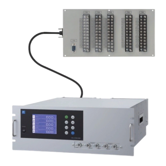
Page 13: Input/Output Terminal Module
2.2 Input/Output terminal module This analyzer provides input/output of various signals from the supplied input/outpt terminal module by connecting the analyzer main unit to this module. <Input/Output terminal module> (2) Input/Output terminal block (TN1 to TN5) (1) Mounting hole (ø4.5, 6 places) (6) Communication connector (CN2) (3) Connector to analyzer main unit <CN1>... - Page 14 3. INSTALLATION DANGER CAUTION or drop, for example, causing accident or injury. injury. 3.1 Installation conditions To install the analyzer for optimum performance, select a location that meets the following conditions; (1) This instrument is system built in type. This instrument should be used while embedded in a panel, locker, or enclosure of steel sheet.
- Page 15 3.2 Installation 3.2.1 Installation of analyzer main frame Installation methods for the analyzer main unit are divided into 2 types; Type External dimensions Mounting dimensions Mounting method 19 inch rack mounting guide rail method Slide rail (Supports mass) 19 inch rack 450 or more mounting slide rail method...
- Page 16 3.2.2 Mounting input/output terminal module (Note) To avoid the effect of noise generated from external units, mount the I/O terminal module mounting plate on the panel for continuity at the mounting surface and con- nect the panel to the same ground as the analyzer main unit. External dimensions Mounting dimensions Mounting method...
- Page 17 3.3 Piping CAUTION inlet. Improper connection may cause accumulation of combustible, toxic, and/or explosive gas in the analyzer. Be sure to connect each pipe correctly. Observe the following when connecting the gas tube. soft vinyl. The analyzer provides inaccurate indication due to gas absorption by piping materi- als.
- Page 18 Internal piping diagram Measuring unit 2 Measuring unit 1 Built-in Built-in sensor sensor OUTLET INLET OUTLET INLET PURGE Sampling gas inlet For measuring unit 1 Sampling gas outlet Sampling cell Note) Sampling gas inlet 2 cells may be used For measuring by combination of unit 2 Sampling gas outlet...
- Page 19 Example of connecting each measuring unit 0.5L/min Exhaust converter 0.5L/min 0.5L/min unit 2 Exhaust Note) The NO /NO converter is used when NO measurement is used for NOx measurement. converter 0.5L/min unit 2 Exhaust Note) The NO /NO converter is used when NO measurement is used for NOx measurement.
- Page 20 3.4 Sampling 3.4.1 Conditions of sampling gas of drain in the gas analyzer. If vapor is contained in the sampling gas, dew point should be mist. consider- able amounts, will shorten the life of instruments. of hot gas directly into the instrument. 3.4.3 Preparation of standard gas condition (once a week).
- Page 21 3.4.5 Pressure at sampling gas outlet Pressure at the sampling gas outlet should be adjusted to atmospheric pressure. monitoring combustion exhaust gas from boiler, refuse incinerator, etc. (1) Gas extractor ZKJ unit Infrared gas analyzer ø10/f8 main unit CO,CO Teflon tube (PUMP) (7) Membrane filter...
- Page 22 3.5 Wiring CAUTION result. CAUTION Please be sure to make ground (grounding) connection for safety. 3.5.1 Power inlet The power inlet is provided at the rear panel of analyzer main unit. When using supplied power cord, connect the female side to the power inlet, and insert the male side into a receptacle matching the rating.
- Page 23 3.5.2 Input/output terminal module This analyzer should be connected to the input/output terminal module by supplied dedicated cable. Plug this cable connector into the receptacle at the rear panel of the analyzer and the receptacle on Ferrite core Ferrite core Analyzer main unit Dedicated cable Input/output...
- Page 24 (2) O sensor input: terminal block 2 (1) - (2) analyzer or external O analyzer prepared sepa- rately. full scale of the analyzer. analyzer, do not use this terminals. CAUTION sensor input is not isolated. It is recommended to isolate when an external O should be installed at a location that is as close to this instrument as possible.
- Page 25 (5) List of terminal blocks Terminal block 1 Terminal block 2 <TN1> <TN2> Note 1 Ch5 remote range Ch10 output Ch5 output – sensor input – – switch input (Ch5_OUT) + (Ch10_OUT) _IN) (R_RNG_Ch5) Ch4 remote range Ch4 output – Ch9 output Ch12 output –...
- Page 26 (6) Description on terminal block Terminal block 1 <TN1> Terminal block 1 Terminal block for analog output (non-isolated out- <TN1> put) Ch10 output Ch5 output – – (Ch5_OUT) + (Ch10_OUT) Ch4 output Ch9 output – – (Ch4_OUT) (Ch9_OUT) Ch3 output Ch8 output –...
- Page 27 Terminal block 3 <TN3> Terminal block 3 <TN3> Ch5 range identification junction terminal.) Unassigned contact output (RNG_ID Ch5) Pump ON/OFF Ch4 range identification when open. Pump off when short- input (R_PUMP) contact output (RNG_ID Ch4) circuited. Ch3 range identification Remote hold input (R_HOLD) contact output (RNG_ID Ch3) when open.
- Page 28 Terminal 4 <TN4> Terminal block 4 It is conductive when peak count <TN4> exceeds the setting time. It Peak count alarm Unassigned output (PEAK_ALM) remains open below the setting time. For setting and operation, Auto calibration status/contact Unassigned output (CAL) Pump ON/OFF Unassigned contact output (PUMP)
- Page 29 Terminal 5 <TN5> Terminal block 5 <TN5> When the output exceeds the set Unassigned Unassigned value, it is conductive between 2 Alarm 6 Alarm 3 output output (ALM_3) Otherwise, it is open between 2 (ALM_6) and 4. Alarm 2 output Alarm 5 (ALM_2) output...
- Page 30 Communication connector <CN2> CAUTION For avoiding electric shock and malfunctions, do not turn on the power supply untill all wiring have been completed. Terminal number Signal name Pin connection 9-pin D-Sub (male) Others CAUTION module). I/O terminal Master module (PC, for ex.) (ZKJ) Communication cable...
- Page 31 Connector to relay board <CN3> Solenoid valve drive signal output for calibration Connector <CN3> (Transister output) Signal output for sample gas selection Signal output for Ch3 span calibration Signal output for Ch4 span calibration Signal output for zero calibration Signal output for Ch5 span calibration Signal output for Ch1 span calibration...
- Page 32 (7) Timing of solenoid valve drive signal for calibration 1) Manual calibration (See “Section 6.9 Calibration”.) 3 - 19...
- Page 33 2) In case of automatic calibration (example shown in Section 6.4.1, Automatic calibration settings) Automatic Ch1 span Ch3 span calibration Ch5 span calibration calibration start calibration Ch4 span Ch2 span Zero calibration calibration calibration Pump ON/OFF contact Sample selection output Zero gas Zero calibration output 350 s...
-
Page 34: Preparation For Operation
4. OPERATION 4.1 Preparation for operation (1) Tube and wiring check 4.2 Warm-up operation and regular operation (1) Operation procedure 1) Turn ON the power switch on the front panel of the analyzer unit. The measurement screen appears on the front display panel in 1 or 2 seconds. 2) Wait for about 4 hours until the instrument is warmed up. -
Page 35: Name And Description Of Operation Panel
5. DESCRIPTION OF DISPLAY AND OPERATION PANELS This section describes the display unit and operation panel of the analyzer main unit. It also explains the name and description of function on the operation panel. 5.1 Name and description of operation panel (1) MODE key (5) UP key (2) ZERO key... -
Page 36: Overview Of Display And Operation Panels
5.2 Overview of display and operation panels Fig. 5-2 5 - 2... - Page 37 5.3 Outline of display screen (1) Measurement mode screen (appears when the power is turned ON) ration as shown as an example is for NO, SO (6) (3) (7) (8) Fig. 5-3 Name and function of measurement mode screen * For outputs of more than 5 channels, scroll the arrow key to view.
- Page 38 Instantaneous concentration value: measured components contained in gas that is now under measurement. conversion concentration values: instantaneous/concentration values and O conversion reference value (see Section 6.8). 21 - On conversion reference value 21 - Os (Value set by application) maintenance mode.) The converted sampling components are NO , SO conversion concentration average value:...
- Page 39 (3) Contents of measured channel (Ch) The following table gives measurement channels and their contents according to the symbols. Code symbol Contents 5th digit 6th digit 22nd digit Ch1: NO Ch1: SO Ch1: CO Ch1: CO Ch1: CH Ch1: NO, Ch2: SO Ch1: NO, Ch2: CO Ch1: CO , Ch2: CO...
-
Page 40: Basic Operation
5.4 Basic operation The measurement mode can be displayed 0 0 . up to 5 channels in a single screen. If 5 0-100 channels or more are to be displayed in a 0 0 . 0-100 single screen, press the key to 0 0 0 scroll the channel one by one. -
Page 41: Switch Of Range
6. SETTING AND CALIBRATION 6.1 Switch of range Measurement Mode 6.1.1 Setting of range switch mode MODE Set the range switch mode as follows. (1) Press the key in measurement mode MODE press the key. cursor by pressing the or the key on the channel selection ponent). - Page 42 6.1.2 Manual range switch The range of the measured component can be switched manually as follows. then press the key. then select a desired range by pressing the or the key. (The mark indicates the currently selected range.) key, and the measure- ment is carried out in the selected range.
-
Page 43: Setting Of Calibration Concentration
6.2 Calibration setting This mode is used to set calibration concentration and actions. The calibration setting involves calibration concentration, zero calibration, calibration range and auto calibration component/range. 6.2.1 Setting of calibration concentration It allows you to set concentrations of the standard gas (zero and span) of each channel used for calibration. - Page 44 screen that appears, select any concentration item (zero, span) you want to set by pressing key. Then press the key, and the selected value is highlighted. Cursor for setting value gas concentration values (zero and span). For value entry, press the key, and a 1-digit value increases or decreases.
-
Page 45: Setting Of Manual Zero Calibration
6.2.2 Setting of manual zero calibration When zero calibration is made manually, set either all measurement components should be cali- brated simultaneously or each component should be calibrated while selecting one by one. Measurement Mode MODE MODE key. Press key. key. - Page 46 key. ponents) to be set can be zero-calibrated selected is zero-calibrated. After setting, press the key. To close the setting To close the manual zero calibration setting or to End of cancel this mode midway, press the key. Manual Zero Calibration Setting A previous screen will return.
- Page 47 6.2.3 Setting of calibration range calibration or auto calibration) should be calibrated with a single range or 2 ranges. Measurement Mode MODE MODE key. Press key. key. Press the key. screen that appears, point the cursor to key. Press the key.
- Page 48 or the key. bration is performed with Range 1 and bration is performed only for the range is performed. Press the key after the selection, and End of Setting of calibration range To close “Setting of Calibration Range” To close “Setting of Calibration Range” or to cancel this mode midway, press the key.
-
Page 49: Setting Of Auto Calibration Component/Range
6.2.4 Setting of auto calibration component/range even when auto calibration is performed. Measurement Mode MODE MODE key. Press key. pressing the key. Press the key. by pressing the key. Press the key. 6 - 9... - Page 50 (5) The cursor next to the range of the se- Select the range to be calibrated mainly by pressing the or the key. (6) Then press the key, and calibration is performed in the selected range. To close "Auto Calibration Component/range"...
- Page 51 6.3 Alarm setting 6.3.1 Setting of alarm values 6 only) setting can be made during measurement. Arbitrary 6 alarm contact outputs can be used. Before changing the alarm setting, set the alarm ON/OFF setting to OFF. Measurement Mode MODE MODE pressing the key.
- Page 52 Cursor for setting value (5) After setting, the alarm setting is now completed by pressing the key. To close the "Alarm Setting" To close the “Alarm Setting” or to cancel this mode midway, press the key. A previous screen will return. Setting range 0% to 100% FS (Settable in each range).
- Page 53 6.3.2 Hysteresis setting To prevent chattering of an alarm output near the alarm setting values, set the value of hysteresis. by pressing the key. Press the key. that appears, enter hysteresis values. For the value entry, 1-digit value is increased or decreased by pressing the key, and pressing the moves the digit.
-
Page 54: Setting Of Auto Calibration
6.4 Setting of auto calibration 6.4.1 Auto calibration Auto calibration is automatically carried out at the time cycle when zero calibration and span cali- bration are set. Before changing the setting of auto calibration, set the ON/OFF to OFF. Measurement Mode MODE MODE key. - Page 55 (1) Press the key in a state where the cur- pears, move the cursor to the gas you want to change the setting by pressing the or the key, and then press the key. key, and then move the cursor to the right by pressing the key.
- Page 56 other cases. Example 12:00 Start Time Cycle 350 sec Flow Time Zero 350 sec Ch1 Span 350 sec Ch2 Span 350 sec Ch3 Span 300 sec Ch4 Span 300 sec Ch5 Span 300 sec EX. time ON/OFF In case where auto calibration is carried out at the above setting. Sunday Monday Tuesday...
-
Page 57: Forced Run/Stop Of Auto Calibration
6.4.2 Forced run/stop of auto calibration Auto calibration can be performed just once or forcibly stopped while the calibration is performed. 6.4.2.1 Execution of auto calibration (only once) pressing the or the key, and then press the key. selection screen that appears, point the pressing the key. - Page 58 6.4.2.2 Forced stop of auto calibration This mode is used to stop the auto calibration forcedly. key. Press the key. selection screen that appears, point the pressing the key. Press the key. the screen is selected while auto calibra- tion is performed.) tion.
- Page 59 “Auto Calibration” screen Example 0 3 . 0 0 0 0 0 0 . 2 1 0 2 9 0 8 0 0 . 0 0 0 0 0 . 0 0 0 9 5 0 . 0 0 0 0 0 .
-
Page 60: Setting Of Auto Zero Calibration
6.5 Setting of auto zero calibration Measurement Mode 6.5.1 Auto zero calibration MODE Auto zero calibration is automatically carried out at the time when zero calibration is set. made are determined by setting of auto cali- bration component in Section 6.2.4. Before changing the setting of auto zero cali- bration, set the ON/OFF to OFF. - Page 61 Auto calibration status contact output is closed during auto zero calibration, and is open in other cases. Example Start time 12:00 Cycle hour Flow time ON/OFF In case where auto zero calibration is carried out at the above setting. Sunday Monday Monday 12:00...
-
Page 62: Forced Run/Stop Of Auto Zero Calibration
6.5.2 Forced run/stop of auto zero calibration Auto zero calibration can be performed just once, or auto zero calibration can be forcibly stopped during calibration. 6.5.2.1 Execution of auto zero calibration (just once) or the key on the user mode screen, and then press the key. - Page 63 6.5.2.2 Forced stop of auto zero calibration This mode is used to cancel the auto zero calibration forcedly. key. Press the key. key. Press the key. when the screen is selected while auto zero calibration is performed.) prompting you to verify that you want to stop auto zero calibration.
- Page 64 “Auto Zero Calibration” screen Example 0 3 . 0 0 0 0 0 . 2 1 0 2 CAUTION During auto zero calibration, any key operation is not permitted other than operations such as key lock ON/OFF and “Stop Auto Zero Calibration.” When the key lock is set at ON, even the “Stop Auto Zero Calibration”...
- Page 65 6.6 Peak alarm setting ment exceeds the set number per one hour, an alarm is provided. The peak alarm and this setting screen appear only when an option is added. Measurement Mode MODE (1) Press the MODE key. Press the key.
- Page 66 Setting range Alarm value : 10 to 1000 ppm 5 ppm step (initial value: 500 ppm) Alarm count : 1 to 99 times 5 ppm step (initial value: 5 times) Hysteresis : 0 to 20 % of full scale 5 ppm step (initial value: 0% of full scale) [% full scale] represents the percentage with the CO range regarded as 100%.
- Page 67 6.7 Parameter setting Description of setting items * For the maintenace mode, see Section 6.8. Measurement Mode MODE MODE key in the measurement mode. by pressing the key. Press the key. Parameter Select setting item appears, point the cursor to any item you want to set by pressing the key.
- Page 68 (4) In the Parameter Setting screen that ap- Parameter Set day of week pears, enter the numeric values and set or setting the items should be carried out Current Time 05/01/27 13:50 by using the key. To move Key Lock the cursor to the right, press the key.
- Page 69 (2) With auto calibration Auto calibration start Auto calibration end Calibration Hold extending time. Output hold Time hold set to the gas flow time (3) External hold Close Open Remote hold Input Output hold (4) Screen display during Holding extending time. (5) If calibration is cancelled after the calibration gas is supplied regardless of during manual cali- bration or auto calibration, the holding extending time will be performed.
- Page 70 Follow the procedures shown below to make the setting. (1) Setting for “Current” output hold value 1) Press the key in a state where the cur- Parameter Select setting item sor is placed next to Hold. Current Time 05/01/27 THU 13:50 Key Lock Output Hold ON Current...
- Page 71 (2) Setting for “Setting” output hold value 1) Press the key in a state ON/OFF is Parameter Select Hold ON or OFF by pressing the or the key. Current Time 05/01/27 THU 13:50 Key Lock Output Hold Current Reset Av. Output Reset Response Time Average Period...
- Page 72 4) The value is highlighted, indicating that value by pressing the or the key, and then move the cursor to the right by pressing the key. 5) After the value is changed, press the key. Meaning of setting The setting is represents the percentage with End of Hold Setting each Ch (component) range regarded as 100% for both ranges.
- Page 73 Average value reset This mode is used to clear O average values and O conversion average values and restarts aver- aging. All average values are reset at a time. The indication value and output value is 0 ppm, Close (hold at least 1.5 sec.) Open Reset input So long as close, resetting lasts.
- Page 74 In case the average period was set to 1 hour. Reset 1 hour Backlight Timer automatically turned off. Press any key to reset backlight OFF. Only when ON is selected, the time until auto Parameter Select ON or OFF OFF is displayed. Press the key in this state, and the time setting can be changed by pressing the...
- Page 75 6.8 Maintenance mode words, etc. First, enter a password and then use it from the next operation. This mode is displayed Parameter Setting screen to display the Password Setting screen. played. Point the cursor to the item you want to set by pressing the and press the key.
- Page 76 Description of Calibration Log screen Past calibration history. Sensor input value, concentration value, and the date when zero/span calibration is performed are logged. The 10 newest calibration data is logged by each Ch (component). Move the cursor to Clear Calibration Log and press the key, and the calibration log is cleared completely.
- Page 77 Description of moisture interference adjustment screen In values on the left side of screen, the moisture interference for each component is already offset. The figures at right are interference compensation coefficients. ponent) by pressing the or the key, and then press the key, and the selected value at right is highlighted.
- Page 78 Description of output adjustment screen Analog output adjustment screen. Connect the digital multi meter to the output terminal corresponding to the number of OUT to be adjusted, and adjust the value so that 4mA or 0V is output at zero and 20mA or 1V is output at span.
- Page 79 Description of each setting screen Password Set : Set the password used to move from the parameter setting screen to the maintenance mode. Arbitrary 4-digit number can be selected. ref. Value : Set the oxygen concentration reference value at the time of oxygen conversion calculation.
- Page 80 The measuring range can be arbitrarily selected in the time of purchase. The range to be used can be selected 1 or 2. ing the or the key, and then press the key. setting is to be changed by pressing the key, and then press the key.
- Page 81 6.9 Manual calibration procedure 6.9.1 Manual zero calibration Measurement Mode It is used for zero point adjustment. For zero calibration gas, suited for an application ZERO (1) Press the ZERO bration screen. ed by pressing the key. After selection, press the key, and zero gas will be supplied.
- Page 82 6.9.2 Manual span calibration It is used to perform a span point adjustment. Supply calibration gas with concentration set to the span value to perform the span calibration. For the span calibration gas for the NO , SO For the span calibration gas for the O measurement, use the standard gas with a concentration of sensor, and use the sensor.
- Page 83 7. MAINTENANCE 7.1 Daily check (1) Zero calibration and span calibration (2) Flow rate check 7.2 Daily check and maintenance procedures Table 7.1 Maintenance and check table Sample gas flow rate (Flow rate of purging gas is included if purging is used) 7 - 1...
- Page 84 7.3 Maintenance of analyzer unit CAUTION adjustment method. The maintenance work that is not described in this section shall be carried out in accordance with CAUTION While the analyzer is in operation, the handle becomes a high temperature part. If you touch the turning off the power supply.
- Page 85 Infrared transmission Bonded together window Window holder O ring Sample gas inlet Sample cell Sample gas outlet Fig. 7-1 Structure of sample cell (pipe cell) 7 - 3...
- Page 86 7.3.2 Cleaning method for sample cell (block cell) This section is strictly factory adjusted. Handle it with utmost attention. (1) Turn off the power switch, stop the sample gas, and allow the zero gas to Top cover cell interior. top cover and remove it. (2) Remove the internal gas inlet tube.
- Page 87 Cell window mounting tool Window fixture O ring holder Outer O ring Inner O ring Infrared transmission window Sample gas inlet or outlet Sample gas inlet or outlet Reference cell unit Sample cell unit Hole for bolt for fixing together with distribution cell and detector Structure of sample cell (of 32, 16, 8, 4, 2 mm long) (sample cell and reference cell are integrated)
- Page 88 7.3.3 Optical zero adjustment method (optical balance adjustment) CAUTION If the following operation is maladjusted, the measurement may adversely be affected. If you are not trained for adjustment, do not carry out this operation but contact the distributor or our service- man.
- Page 89 ⓐ to ⓓ in 1-1 and 1-2 become as close to 0 as possible within ±100 range. ⓔ to ⓗ in 2-1 and 2-2 become as close to 0 as possible Optical zero adjustment knob within ±100 range. (4) Operate the optical zero adjustment Optical system 2 knob to change the value displayed at ⓐ...
- Page 90 introduce bubbled N or air gas to the ana- ponent) by pressing the key, adjust the value at right by pressing the or the key so that the value at left falls within ±10 (make it as close to 0 as possible), and then press the integrally.
- Page 91 7.4 Long term maintenance Gas analyzer annual inspection plan The recommended replacement period of components varies depending on the installation conditions. 1) The recommended replacement period is a recommended standard criterion, and varies de- 2) The recommended replacement period is not the warranty period. It is provided as a preventative maintenance program baseline schedule.
- Page 92 7.5 Replacement of fuse Fuse honder Note) Prior to the following work, be sure to repair blown down fuse (short, etc), if any. cap will be removed. Remove a fuse out of the holder. Replace it with a new one. if the analyzer starts up normally.
- Page 93 8. ERROR MESSAGE If errors occur, the following contents are displayed. Error contents Probable causes Error No.1 Motor rotation detection signal faulty It is recommendable to exchange the motor once two years. Error No.5 Amount of zero calibration (indication value) is over 50% of full scale.
- Page 94 Calibrated forcedly Calibration is continued. Unless another calibration 9 0 8 0-25 error occurs, calibration is carried out to the end, the 1 3 6 Measurement screen returns. 0-100 0 0 0 0 0-10 0-100 0 0 9 0-25 nance mode. Error log screen Date and time when an error occurred.
- Page 95 SPECIFICATIONS Relay contact output: SPECIFICATIONS auto calibration status, pump ON/OFF, peak alarm. outputs) Measurement principle: High/Low limit alarm contact output. NO, SO , CO , CO, CH Power disconnection alarm. Non-dispersive infrared (NDIR) method, Single light source and double beams (double-beam internal circuit.
- Page 96 Remote output holding: Calibration error contact output: The contact is closed if a calibration error (error No. 4, allows you to hold the output signal to the last value or 5, 6, 7, or 9) occurs. Auto calibration status contact output: The contact is closed during auto calibration.
- Page 97 Zero drift: EU Directive Compliance ±1% of full scale per week LVD (2014/35/EU) ±2% of full scale per week (for ranges between 0–50 EN 61010-1 ppm and 0–200 ppm) EN 62311 ±2% of full scale per day (for ranges below 0–50 ppm) EMC (2014/30/EU) Span drift: EN 61326-1 (Table 2)
- Page 98 9.2 Code symbols □□□□ 6- □□□□□□ - □□□□□□ - □□□ Digit No. 1 2 3 4 5 6 7 9 10 11 12 13 14 15 16 17 18 19 20 21 22 23 of code Digit Description note Z K J F <Custom specifications>...
- Page 99 Digit No. 1 2 3 4 5 6 7 9 10 11 12 13 14 15 16 17 18 19 20 21 22 23 of code Digit Description note Z K J F <Measuring range> 4th component note 4 Minimum range Maximum range None None...
- Page 100 9.3 Measurable component and range – availability check table – (1) Components of single-component analyzer and double-component analyzer (NO/CO), and CO of 3-component analyzer (NO/SO /CO) As shown in the range code, when “P”, “A”, “D”, “B”, and “E” are specified at 5th digit, each component is given at 11th and 12th digits.
- Page 101 (4) N O/CO of 2-component analyzer N O/CO , 3-component analyzer NO/N O/CO , SO O/CO O/CO /CO, CH O/CO and 4-component analyzer (NO/SO O/CO Range code: When code symbol is "R" or "U", N O is 11th and 12th digit, CO is 13th and 14th digit.
- Page 102 9.4 Outline diagram <Analyzer main unit> <Side> <Upper> M4 (for mounting slide rail) <Front> Sample gas inlet Rc1/4 or NPT1/4 Power switch <Rack mounting hole> JIS : 100mm EIA : 101.6mm Sample gas outlet Rc1/4 or NPT1/4 Purge gas inlet Rc1/4 or NPT1/4 <Rear>...
- Page 103 <Input / output terminal module> (Accessory) Mounting hole 6-ø4.5hole Terminal Terminal Terminal Terminal Terminal block block block block block <TN1> <TN2> <TN3> <TN4> <TN5> Screw terminals M3.5 Communication connector <CN2> (280) Connector to analyzer main unit <CN1> Connector to relay board <CN3> <Cable for connecting input / output terminal>...
- Page 104 Outline diagram of accessory slide rail (unit: mm) when designated. Closed Model: 305A-24/Accuride International Inc. 632±3 Cabinet member The same or less 1.52t Open (22.7) (9.5) Intermediate member 610±0.3 Drawer member 577.8±0.3 15.9±0.3 1.27t 565.1±0.3 454±0.3 111.1±0.3 25.4±0.3 12.7±0.3 12.7±0.3 4.4 ×...
- Page 105 <Exclusive relay board> ule and directly driving the solenoid valve for calibration. OUTLINE DIAGRAM (Unit: mm) 15 or less Mounting hole ø4.5 CN13 CN1 CN2 CN3 CN4 CN5 CN6 CN7 CN8 CONNECTIONS Reserved Solenoid valve Solenoid valve driving power For switching For zero gas sample For span gas...
- Page 106 Instrumentation & Sensors Planning Dept. 1, Fuji-machi, Hino-city, Tokyo 191-8502, Japan www.fujielectric.com Phone: +81-42-514-8930 Fax: +81-42-583-8275 www.fujielectric.com/products/instruments/...
Need help?
Do you have a question about the ZKJ Series and is the answer not in the manual?
Questions and answers