Sign In
Upload
Manuals
Brands
Fuji Electric Manuals
Measuring Instruments
FSX
Fuji Electric FSX Manuals
Manuals and User Guides for Fuji Electric FSX. We have
1
Fuji Electric FSX manual available for free PDF download: Instruction Manual
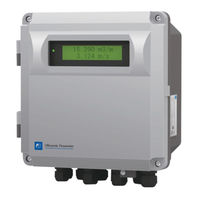
Fuji Electric FSX Instruction Manual (138 pages)
ULTRASONIC FLOWMETER FOR STEAM
Brand:
Fuji Electric
| Category:
Measuring Instruments
| Size: 7 MB
Table of Contents
Safety Precautions
4
Caution on Installation Location
7
Table of Contents
8
Product Outline
10
Overview
10
Checking Delivered Items
10
Check on Type and Specifications
11
Name and Function of each Part
13
Flow Transmitter (FSJ)
13
Detector (FSX)
14
Operation Preparation
15
Outline of Installation Procedure
15
Tools Required for Installation
16
Installation
17
Installation Location of Flow Transmitter
18
Detector Installation Location
19
Conditions on Straight Pipe
20
Mounting Orientation
21
Installation of Flow Transmitter
22
Wall Mounting
22
Pipe Stand Mounting
23
Flow Transmitter Wiring
24
Cautions in Wiring
24
Applicable Wires
24
Treatment of Wiring Port
24
Wiring to each Terminal
25
How to Connect to Terminal Block
26
Cable Treatment
26
How to Connect to Power Supply/Signal
27
Terminal Block
27
Method for Connecting to Communication Board and Temperature Measurement Board Terminal Block
28
Operation
28
Points of Caution When Operating Equipment
28
Parameters
29
Description of Display/Setting Unit
29
Display/Setting Unit
29
Description of Display/Setting Unit
30
Composition of Key Operation
31
Parameter Initial Value List
34
Parameter Protection
36
Protection ON/OFF
36
Display Language
37
How to Select the Language
37
Specifications/Detector
38
Checking Piping Parameter
38
Piping Parameter Setting Method
39
Setting of Unit
41
Unit System
41
Volume Flow Unit Setting Method
42
Volume Total Unit Setting Method
43
Mass Flow Unit Setting Method
44
Mass Total Unit Setting Method
45
Pressure Unit Setting Method
46
Temperature Unit
47
Output Setting
48
Setting of Flow Rate Range
48
Volume Flow Range (Single Range)
48
Setting the Mass Flow Rate Range
50
Range
50
The Source of Analog Output
51
Analog Output at Error (Burnout)
52
Output Limit
53
Setting the Total (Actual)
55
Total Flow Pulse
55
Width)
56
Preset Value for Total Flow
57
Setting the MASS TOTAL Pulse (MASS TOTAL Rate, Pulse Width)
58
Setting the MASS TOTAL Preset Value
59
TOTAL Mode (Total Reset, Start, Stop)
60
Totalization Processing at Error (Burnout)
61
DO Output
62
Total Pulse Output
63
LCD Indication
64
Damping
65
Low Flow Rate Cutting
66
Application Operation of Parameter
67
Automatic 2 Ranges
67
Bi-Directional Range
69
Bi-Directional Auto 2 Range
71
Rate Limit
73
DO Output
75
FULL SCALE 2 Output
75
Alarm Output
76
Flow Switch
77
Total Switch
79
Range over Output and Pulse Range over
80
Output
80
Output at the Minus Flow Direction
81
Input Alarm Setting Method
82
How to Set the Maintenance Period
83
Calibrating the Measured Value
84
Input Settings
85
AI Range Setting (Option)
85
Temperature Input Setting (Option)
87
Maintenance Mode
88
Calibrating the Analog Output
88
Constant Current Output
89
Checking the Total Pulse Output Action
90
Checking the Status Output
91
Analog Input Calibration Method
92
Analog Input Check Method
93
Confirming the Input Temperature
94
Test Mode (Simulated Flow Rate Output)
95
Serial Transmission (RS-485)
97
Setting the ID no
99
Confirming the Software Version
99
LCD Backlight Setting
100
Receipt Signal Auto Search
101
Maintenance Period Setting
102
Mounting of Detector
103
Detector Mounting Procedure
103
Mounting of Detector
104
Mounting Dimensions Diagram
104
Selecting the Mounting Location
105
Treatment of Detector Mounting Surface
107
Mounting the Noise Elimination Frame
108
Sensor Mounting Bracket Mounting
109
Sensor Mounting
110
Pre-Anplifier Mounting
111
Wiring Connection
112
Thermal Insulating Material Application
113
Precautions for Removing the Noise Elimination
114
Frame
114
Check and Maintenance
115
Daily Check
115
Periodic Inspection
115
Reapplying Grease
115
How to Measure the Insulation Resistance
116
Error and Remedy
117
Display Error
117
Checking the LCD/LED
117
Checking the LED Lit in Red
118
Checking the RAS Information
123
Displaying the Data in Maintenance Mode
124
Key Error
125
Error in Measured Value
126
When "SNR ALARM" Is Displayed
126
Error in Analog Output
127
Error in Input Temperature
127
Remedying a Hardware Fault
127
Appendix
128
Specifications
128
Outline Diagram
131
Parameter List
133
Piping Data
136
Advertisement
Advertisement
Related Products
Fuji Electric FSC-2
Fuji Electric FSC-3
Fuji Electric Time Delta-C FSV-2
Fuji Electric FSC-4
Fuji Electric FSS-1
Fuji Electric FSD-1
Fuji Electric FSJ
Fuji Electric FSZ
Fuji Electric FSZ08
Fuji Electric FSZ15
Fuji Electric Categories
Air Conditioner
Inverter
Measuring Instruments
Controller
Control Unit
More Fuji Electric Manuals
Login
Sign In
OR
Sign in with Facebook
Sign in with Google
Upload manual
Upload from disk
Upload from URL