Table of Contents
Advertisement
Quick Links
Advertisement
Table of Contents

Related Manuals for Prodigit 3270 Series


Summary of Contents for Prodigit 3270 Series
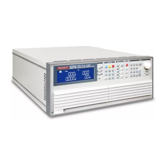
- Page 1 3270 Series AC/DC High power Electronic Load Operation manual S/N:900327002 REV:D...
- Page 2 会也可能不会含有所有所列的部件。This table shows where these substances may be found in the supply chain of Prodigit electronic information products, as of the date of sale of the enclosed product. Note that some of the component types listed above may or may not be a part of the enclosed product. ○:表示该有毒有害物质在该部...
- Page 3 Failure to comply with these precautions or with specific warnings elsewhere in this manual violates safety standards of design, manufacture, and intended use of the instrument. PRODIGIT assumes no liability for the customer's failure to comply with these requirements.
- Page 4 DECLARATION OF CONFORMITY Company Name: PRODIGIT ELECTRONICS CO., LTD Address: 8F, No.88, Baojhong Rd., Sindian District, New Taipei City,Taiwan. Declares under sole responsibility that the product as originally delivered Product Names: AC/DC Electronic Loads Model Numbers: 3270, 3271, 3272, 3273, 3274...
- Page 5 SAFETY SYMBOLS Direct current (DC) Alternating current (AC) Both direct alternating Three-phase alternating current Protective earth (ground) On (Supply) Off (Supply) Fuse Caution!Refer to this manual before using the meter. Caution, risk of electric shock CAT IV – Is for measurements performed at the source of the low-voltage installation.
-
Page 6: Table Of Contents
3270 series AC/DC load operation manual Table of Contents Chapter 1 Introduction ··························································································· 1 1-1. ············································································· 1 ENERAL DESCRIPTION 1-2. ·························································································· 11 EATURES 1-3. ········································································ 11 TANDARD CCESSORIES 1-4. ····························································································· 12 PTION 1-5. 1 ················································································· 12 PECIFICATIONS 1-6. 2 ················································································· 13 PECIFICATIONS Chapter 2 Installation ···························································································... - Page 7 5-7. ······················································ 124 ATTERY DISCHARGE TEST APPLICATION 5-8. ····················································· 127 URRENT PROTECTION COMPONENT TEST 5-9. ······························································ 129 RECTIFIED LOAD SIMULATION 5-10. ··········································································· 130 ARALLEL OPERATION 5-11. ) ·············································································· 131 NRUSH URRENT 5-12. ·································································· 132 OWER UPPLY TESTING 5-13. ··································································· 134 OWER UPPLY TESTING...
- Page 8 Fig 3-1 3270 Series SIZE description ······································································ 23 Fig 3-2 3270 Series Rear Panel ············································································· 24 Fig 3-3 typical connection of 3270 series load module ················································ 71 Fig 3-4 typical connection of 3270 series load module ················································ 71 Fig 3-5 An equivalent circuit in terms of the current monitor ········································· 72 Fig 3-6 (Correct) Connections to an oscilloscope ·······················································...
- Page 9 Tables Table 1-1 3270 Series Specifications ······································································ 12 Table 1-1A 3270 Series Specification ······································································ 14 Table 3-1 ·········································································································· 83 Table 3-2 AUTO SEQUENCE 3PH MODE can not be used command ··························· 83 Table 3-3 3PH MODE GLOB command ··································································· 83 Table 3-4 3270 initialize ·······················································································...
-
Page 10: Chapter 1 Introduction
Distortion of Current( ITHD) , Current Harmonic( IH) When Turbo ON, power and current increase 2 times 3270 Series is suitable for the step, square and sine wave of the AC Power device test, Especially For the uninterruptible power supply UPS, Inverter, fuses, circuit breakers, power Regulator AVR, Battery, AC / DC power supply / components ... - Page 11 2 PRODIGIT • 3270 LOAD Operating mode...
- Page 12 3270 Series Operation Manual 3 The most complete measurement function 3270 series AC / DC electronic load has built-in 16-bit precision measurement circuit, providing accurate measurement values, measuring items include voltage (Vrms), current rms (Arms), watts (Watt), voltampere (VA), crest factor (CF), power...
- Page 13 4 PRODIGIT • Parallel and three-phase control 3 phase Y connection 3 phase △ connection...
-
Page 14: Fig 1-1 3270 Power Contour
3270 Series Operation Manual 5 3270 Series AC/DC electronic load can be used to work with GPIB, RS232, USB or LAN interface and panel manual operation can be made available. The work area of 3270 3750W is as shown in Fig.1-1. The work scope of its voltage and current is 0-350Vrms and 0- 37.5Arms respectively. -
Page 15: Fig 1-4 3273 Power Contour
Complete AC and DC load modes • AC load mode 1.1.1. CC Mode With the operating mode of Constant Current, the 3270 series electronic load will sink a current in accordance with the programmed value regardless of the input voltage (see Fig.1-6). -
Page 16: Fig 1-7 Constant Current Mode
3270 Series Operation Manual 7 1.1.2. Linear C.C. Mode During Linear C.C. mode, the load current input into 3270 Series High Power Electronic Load depends on the current setting regardless of the input voltage, e.g., the current setting remains unchanged. Please refer to Fig.1-7. The load input current signal will follow input voltage signal, That is useful for step wave-form and square wave-form device. -
Page 17: Fig 1-9 Constant Voltage Mode
Voltage Setting Fig 1-9 Constant Voltage mode 1.1.5. CP Mode: At Constant Power mode, the 3270 series Electronic Load will attempt to sink load power (load voltage * load current) in accordance with the programmed power. (See Fig 1-10). Power Setting... -
Page 18: Fig 1-11 Constant Current Mode
3270 Series Operation Manual 9 • DC load mode 1.1.6. CC Mode With the operating mode of Constant Current, the 3270 series electronic load will sink a current in accordance with the programmed value regardless of the input voltage (see Fig.1-11). Current Setting Fig 1-11 Constant Current mode 1.1.7. -
Page 19: Fig 1-13 Constant Power Mode
10 PRODIGIT 1.1.8. CP Mode: At Constant Power mode, the 3270 series Electronic Load will attempt to sink load power (load voltage * load current) in accordance with the programmed power. (See Fig 1-13). Fig 1-13 Constant Power mode 1.1.9. CV Mode: At Constant Voltage mode, the 3270 series Electronic Load will attempt to sink enough current until the load input voltage reaches the programmed value (see Fig 1-14). -
Page 20: Features
3270 Series Operation Manual 11 1-2. Features The main features of the 3270 series of load are highlighted below. 1.2.1. Four meters can be displayed V/A/W Meter, display the Voltage (Vrms, Vpeak, Vmax., Vmin), Current (Irms, I Peak, Imax. Imin.) Watt, Voltampere (VA), Frequency, Crest... -
Page 21: Ption
177 mm x 440 mm x 558 mm 21.5 Kg 3273 3750W 350V 177 mm x 440 mm x 558 mm 33.5 Kg 3274 2800W 350V 18.75A 177 mm x 440 mm x 558 mm 27.5 Kg Table 1-1 3270 Series Specifications... -
Page 22: Specifications 2
3270 Series Operation Manual 13 1-6. Specifications 2 MODEL 3270 3271 3272 3273 3274 3750 W 2800W 1875 W 3750 W 2800W Power (W) 37.5 Arms / 112.5Apeak 28 Arms / 84Apeak 18.75 Arms / 56.25Apeak 28 Arms / 84Apeak 18.75 Arms / 56.25Apeak... -
Page 23: Table 1-1A 3270 Series Specification
*1 ms (millisiemens) is the unit of conductance(G), one siemens equal to 1/Ω *2 Operating temperature range is 0~40℃, all specification apply for 25℃±5℃, Except as noted * All specifications subject to change without notice. Table 1-1A 3270 Series Specification... -
Page 24: Chapter 2 Installation
Prodigit's sales and service office or representative. Your 3270 Series high power AC/DC load was shipped with a power cord for the type of Terminal blocks used at your location. If the appropriated cord was not included, please contact your nearest Prodigit sales office to obtain the correct cord. -
Page 25: Grounding Requirements
2-4 Grounding requirements SHOCK HAZARD 1. It is requested to use the 3Pin plug connector only for 3270 Series mainframe to out of danger when electric leakage. And the complete and proper grounded is necessary. 2. The 3270 Series high power AC/DC load is equipped with three conductor cable which... -
Page 26: Environmental Requirements
Transient Overvoltage on the mains supply can be 2500V. 2-6 Repair If the instrument is damaged, please attach a tag to the instrument to identify the owner and indicated the require service or repairing. And inform the Prodigit sales and service office or representative. 2-7 Cleaning Use a soft or slightly damp cloth to clean this product. -
Page 27: Connection To The Load Input Terminal On The Rear Panel
2-10 GPIB & RS232 connection option 2.10.1. GPIB + RS232 connector is on the rear panel of 3270 Series Mainframe for application GPIB or RS232 . 2.10.2. GPIB and RS232 interface can only be used at the same time, to Change the interface must reboot unit. -
Page 28: Gpib Connection Option
Of devices connected together, up to 20 meters maximum. Fig 2-5 3270 Series GPIB Rear panel 2-13 USB Connection option Fig 2-6 shows the USB connector in the rear panel of 3270 Series mainframe. Please Refer Appendix B. Fig 2-6 3270 Series USB Connection 2-14 LAN Connection option Fig 2-7 shows the LAN connector in the rear panel of 3270 Series mainframe. -
Page 29: Load Wire Inductance
This voltage applies to all of the load input terminals of the 3270 series when the impedance of the EUT is relatively small. The voltage generated by the load wire inductance (L) and the current variation (I) is expressed using the following equation. -
Page 30: Fig 2-9 Waveform Example: Generate Unstable Oscillation
In the case of DC operation also, the phase delay of the current may cause instability in the 3270 Series Control inducing oscillation. In this case also, connect the 3270 Series and the equipment under test using the shortest twisted wire possible. -
Page 31: Fig 2-10 Length Of Wiring
22 PRODIGIT If only DC operation is required, a capacitor may be connected to the load Input Terminal as shown in Fig. 2-10 to alleviate oscillation. In this case, use the capacitor within its Allowable ripple current. Keep the wire short... -
Page 32: Chapter 3 Operation
3270 Series Operation Manual 23 Chapter 3 Operation This chapter describes the front panel function and operation of each 3270 Series load, The Remote Control is described in Chapter 4. 3-1. 3270 Series Size description Fig 3-1 3270 Series SIZE description... -
Page 33: 3270 Series Panel Diagram
24 PRODIGIT 3-2. 3270 series panel diagram Fig 3-2 3270 Series Rear Panel... -
Page 34: Lcd Display Description
MODE 3.3.3. mode, LCD On the 3270 Series AC/DC Electronic Load, there are 5 working modes which can be selected by MODE KEY with the sequence of Constant Current, Linear Constant Current, Constant Resistance, Constant Power and Constant Voltage. Then switching can be made in such a sequence. - Page 35 26 PRODIGIT Normal mode: The left 5 digit display displays the voltage present at the load’s input terminals. The value displayed will include the automatic voltage compensation if the sense Terminals are also connected to the device under test (DUT) .
- Page 36 3270 Series Operation Manual 27 Setting Mode: The right display together with the rotary adjustment knob is used to set values. The value changes according to the setting function that is active. The middle LCD provides a text message to tell the user which part of the setting menu is active.
- Page 37 Peak 3.3.9. Meter There are three operating modes. These can be selected in turn by pressing the " Meter” key on the 3270 series AC/DC Electronic Load. The sequence is: Freq 3.3.10. WATT/VA/VAR Key There are three operating modes. These can be selected in turn by pressing the “WATT/VA/VAR”...
- Page 38 3270 Series Operation Manual 29 3.3.11. There are four operating modes. These can be selected in turn by pressing the “THD” key on the 3270 series AC/DC Electronic Load. The sequence is: V_THD I_THD • In V_H operating modes, these can be selected in turn by pressing the “PF/CF/FREQ”...
- Page 39 CC, LIN, CR, CP, CV Indicator There are five operating modes. These can be selected in turn by pressing the "MODE" key on the 3270 series AC/DC Electronic Load module. The sequence is: (CC) Constant Current (LIN) Linear Constant Current ...
- Page 40 3270 Series Operation Manual 31 LOAD 3.3.13. Key and LED The input to the 3270 series AC/DC Electronic Load can be switched ON/OFF by Using the “LOAD” button. Indication of the ON/OFF state is provided by illumination Of the Button. LOAD button lit...
- Page 41 32 PRODIGIT 3.3.16.2. Linear Constant Current (LIN) mode: The A and B levels of load current can be preset at right lower 5 digit LCD. the "A" LED will be lit indicating the setting value is amps. 3.3.16.3. Constant Resistance (CR) mode: The A and B levels of load resistance can be preset on the right lower 5 Digit LCD.
- Page 42 3270 Series Operation Manual 33 Setting upper limit voltage VH , the right upper 5 digit monitor display the ”V- Hi” and right lower monitor display upper limit of the voltmeter with the unit as "V" ,The V-Hi set range from 0.00 V to 600.00V step 0.01V by rotating the Setting knob.
- Page 43 34 PRODIGIT Setting Upper limit current IH , the right upper 5 digit monitor display ”I-Hi” and right lower monitor display upper limit of the voltmeter with the unit as "A", The I-Hi set range from 0.000 A to 40.000A step 0.001A by rotating the Setting knob.
- Page 44 3270 Series Operation Manual 35 Setting OPL, the right upper 5 digit monitor display ”OPL” and right lower monitor display upper limit of the voltmeter with the unit as "W", The OPL set range from 0.1W to 3937.5W step 0.1W by rotating the Setting knob.
- Page 45 36 PRODIGIT CR mode, press limits key to set the V-Hi and V-Lo voltage upper and lower limits of the GO / NG. High Load input Voltage Resistance Load Current CV mode, press limits key to set the I-Hi and I-Lo Current upper and lower limits of the GO / NG.
- Page 46 3270 Series Operation Manual 37 Config 3.3.18. The CONFIG key allows the sense function to engage automatically or switched ON. The CONFIG key also enables the LOAD to automatically turn ON/OFF When a voltage level is reached. Each press of the CONFIG key moves the menu on one step. On first press of the CONFIG key the button will illuminate and EXTIN will be displayed on the Right upper LCD.
- Page 47 38 PRODIGIT The right upper 5 digit monitor display the EXTIN and right lower monitor display OFF or ON for external input disable or enable, Default is OFF NOTE: This feature is optional. (This option is not displayed if this feature is not selected) ...
- Page 48 3270 Series Operation Manual 39 The right upper 5 digit monitor display the CPRSP and right lower monitor Display 0 for CPRSP value. The range is 0~7, Default is 0. CPRSP is set to the constant power response speed 0~3 for linear current constant power load, 0 is the fastest to adjust the load power response, 3 is the slowest.
- Page 49 40 PRODIGIT Key and √2, 2, 2.5, 3, 3.5 key 3.3.19. CF key only functions upon C.C. and C.P. mode and all LED off upon Linear C.C., C.R. and C.V. mode. √2, 2, 2.5, 3, 3.5 keys are used to quick change the current C.F.
- Page 50 3270 Series Operation Manual 41 • Press the CF key, and 2 key settings will be automatically saved and exit. • Press the CF key, and 2.5 key settings will be automatically saved and exit. • Press the CF key, and 3.0 key settings will be automatically saved and exit.
- Page 51 Knob, press the ENTER key after the completion of the setting will be automatically Stored. Note: CF( crest factor) range 1.4 ~ 5.0, 3270 series full scale current is 3 times the peak, if use the CF peak 5.0, 3270 full scale current so the current must be reduced to 22.5A, in order to reach the peak 5.0.
- Page 52 3270 Series Operation Manual 43 positive half-cycle or negative half-cycle load setting Use the knob and key to adjust the CF value, or press the CF key, the Keypad key enters 1.1 (LDNEG), the monitor displays “LDNEG “is negative half-cycle loading, the Keypad key enters 1.0 (LDPOS),”LDPOS”...
- Page 53 44 PRODIGIT • Press the FREQ key and 50Hz key settings will be automatically saved and exit. • Press the FREQ key and 60Hz key settings will be automatically saved and exit. • Press the FREQ key and 400Hz key settings will be automatically saved and exit.
- Page 54 3270 Series Operation Manual 45 3.3.21. Key and 1, 0.9, 0.8, 0.7 and 0.6 PF(lead) key only functions upon C.C. and C.P. mode and all LED off upon Linear C.C., C.R. and C.V. mode. 1, 0.9, 0.8, 0.7 and 0.6 keys are used to quick change the P.F.(Crest Factor) of C.C.
- Page 55 46 PRODIGIT • Press the PF key, and key settings will be automatically saved and exit. • Press the PF key, and key settings will be automatically saved and exit. • Press the PF key, setting range from 0.01 to 1.00, step 0.01 by rotating the Setting knob, press the ENTER key after the completion of the setting will be automatically stored.
- Page 56 3270 Series Operation Manual 47 • Press the -PF key, and key settings will be automatically saved and exit. • Press the -PF key, and key settings will be automatically saved and exit. • Press the -PF key, and key settings will be automatically saved and exit.
- Page 57 48 PRODIGIT • Press the -PF key, and key settings will be automatically saved and exit. Press the PF key, setting range from- 0.01 to -1.00, step 0.01 by rotating the Setting knob, press the ENTER key after the completion of the setting will be...
- Page 58 Item, Setting and Exit key for Test Item Test item as following There are eight operating modes. These can be selected in turn by pressing the “Item “key on the 3270 series AC/DC Electronic Load module. The sequence is: ...
- Page 59 • The SHORT parameters setting: The SHORT test will attempt to sink high current up to the 3270 series AC/DC load Maximum current in order to check the power source’s protection and behavior. The test time can be adjusted and threshold values for the High and low voltage Limits set.
- Page 60 3270 Series Operation Manual 51 SHORT TIME: setting the Short test time, the left 5 digit monitor display the ”SHORT” ,the right upper 5 digit monitor display the TIME and right lower monitor display “100ms” , the range is 100ms to 10000ms.
- Page 61 52 PRODIGIT “OPP PRESS START” will be shown across the displays. Each press of the Setting button moves the menu on one step. The Left and Middle LCDs show the currently selected test parameter as text. The value is adjusted by The rotary knob and can be read from the Right display during Setting.
- Page 62 3270 Series Operation Manual 53 PSTOP: setting the stop power, the Left 5 digit monitor display the “OPP” ,the right upper 5 digit monitor display the “PSTOP”, and right lower monitor display setting value, the unit is "W". The range is 0.1W to the full scale of the CP mode specification.
- Page 63 54 PRODIGIT The right upper 5 digit monitor display the Turbo and right lower monitor display “OFF” ,use the knob and the key to switch ON or OFF. ISTAR: setting the start current point, the Left 5 digit monitor display the “OCP”...
- Page 64 3270 Series Operation Manual 55 Vth: Setting threshold voltage; the Left 5 digit monitor display the “OCP” ,the right upper 5 digit monitor display the “VTH”, and right lower monitor display setting value, the unit is "V". The range is 0.01V to the full scale of the Voltage specification.
- Page 65 56 PRODIGIT Non-L CC: setting the Non-L current point, the Left 5 digit monitor display the “Non-L” ,the right upper 5 digit monitor display the “CC”, and right lower monitor display setting value, the unit is "A". The range is 0.001A to the full scale of the CC mode specification.
- Page 66 3270 Series Operation Manual 57 NL+CR CR: setting the NL+CR CR resistance point, the Left 5 digit monitor display the “NL+CR” ,the right upper 5 digit monitor display the “CR”, and right lower monitor display setting value, the unit is "Ω" , use the knob and button to set the CR value from 1.6000Ω...
- Page 67 58 PRODIGIT FUSE CC : setting the fuse current point, the Left 5 digit monitor display the “FUSE” ,the right upper 5 digit monitor display the “CC”, and right lower monitor display setting value, the unit is "A", Use the knob and button to set the FUSE CC current value the range from 0.000A to full scale current of the CC mode...
- Page 68 3270 Series Operation Manual 59 The Left 5 digit monitor display the “BATT”, the right upper 5 digit monitor Display the “MODE”, and right lower monitor display the “CC”, use the knob and the key to switch CC, LIN, CR or CP.
- Page 69 60 PRODIGIT BATT CF: setting the CF, the Left 5 digit monitor display the “BATT” ,the right upper 5 digit monitor display the “CF”, and right lower monitor display setting value. The range is 1.0、1.1、1.2、1.3、1.4 ~5.0,the setting sequence is shown below: ...
- Page 70 3270 Series Operation Manual 61 BATT TIME: setting the Battery test time, the Left 5 digit monitor display the “BATT” ,the right upper 5 digit monitor display the “TIME”, and right lower monitor display setting value, the unit is "S". The range is 1S ~99999S.
- Page 71 62 PRODIGIT BATT TIME: setting the BATT TIME, the Left 5 digit monitor display the “BATT” ,the right upper 5 digit monitor display the “TIME”, and right lower monitor display setting value, the unit is "S". The range is 1s to the 99999s.
- Page 72 3270 Series Operation Manual 63 BATT TIME: setting the BATT TIME, the Left 5 digit monitor display the “BATT” ,the right upper 5 digit monitor display the “TIME”, and right lower monitor display setting value, the unit is "S". The range is 1s to the 99999s.
- Page 73 64 PRODIGIT BATT CP : setting the BATT CP, the Left 5 digit monitor display the “BATT” ,the right upper 5 digit monitor display the “CP”, and right lower monitor display setting value, the unit is "W". The range is 0.1W to the full scale of the CP mode specification.
- Page 74 3270 Series Operation Manual 65 BATT CF: setting the PF, the Left 5 digit monitor display the “BATT” ,the right upper 5 digit monitor display the “PF”, and right lower monitor display setting value. The range is 0.01 ~1.00.
- Page 75 66 PRODIGIT • The INRUS parameters setting: Pressing the Item key once will cause the button to illuminate. The message “INRUS PRESS START” will be shown across the displays. Each press of the setting button moves the menu on one step. The Left and right LCDs show the currently selected test parameter as text.
- Page 76 3270 Series Operation Manual 67 INRUS ISTEP : setting the INRUS ISTEP, the Left 5 digit monitor display the “INRUS” ,the right upper 5 digit monitor display the “ISTEP”, and right lower monitor display setting value, the unit is "A". Use the knob and button to set the ISTEP current value, the setting range from 0.000 A to 75.000A.
- Page 77 68 PRODIGIT SURGE FREQ: setting the SURGE FREQ, the Left 5 digit monitor display the “SURGE”, the right upper 5 digit monitor display the “FREQ”, and Right lower monitor display setting value, the unit is "Hz”, use the knob and button to set the Frequency value, the setting range from DC and 40~ 440Hz.
- Page 78 3270 Series Operation Manual 69 SURGE S2 : setting the SURGE S2, the Left 5 digit monitor display the “SURGE” ,the right upper 5 digit monitor display the “S2”, and right lower monitor display setting value, the unit is "A”, use the knob and button to set the second surge current value, the setting range from 0.000A to the 75.000A.
- Page 79 70 PRODIGIT 3.3.25. ROTARY Knob and ARROW Keys The ROTARY knob and ARROW keys are used to increase or decrease the set values. Clockwise the rotary switch and UP arrow key to increase the setting values. Anti-clockwise the rotary switch and DOWN arrow key to decrease the setting values..
-
Page 80: Fig 3-3 Typical Connection Of 3270 Series Load Module
3.3.26. DC INPUT Terminal. When Load Input Connector is used, be sure that the rated specification of the Voltage and current of the 3270 Series AC/DC Electronic Load shall not be Exceeded. Fig 3-3 typical connection of 3270 series load module 3.3.27. -
Page 81: Fig 3-5 An Equivalent Circuit In Terms Of The Current Monitor
For example. 3270: Imax = 37.5A therefore I-monitor 10V = 37.5A so 1V = 3.75A Please refer to the specification Fig 1-1.1 to Fig1-1.20 for the maximum current that each 3270 series Load is capable of. The current monitor of this unit is NOT isolated. Please be careful when you connect an oscilloscope. -
Page 82: Fig 3-6 (Correct) Connections To An Oscilloscope
3270 Series Operation Manual 73 Connecting the I-monitor to an oscilloscope When you connect this product to an oscilloscope, please ensure the correct polarities of the connecting probes as shown in Fig. 3-6. Fig 3-6 (Correct) Connections to an oscilloscope... -
Page 83: 3270 Series Operating Instructions (1)
The analog programming input is configured as a terminal on the mainframe’s rear panel. The 3270 series Load will attempt to load proportionally according to the signal and the load module’s maximum current or power range. For example: 3270: Imax = 37.5A and Pmax =3750W... -
Page 84: 3270 Series System Operating Instructions (3)
“GPIb”, the right upper 5 digit monitor display "Addr", the right lower 5 digit monitor display setting GPIB address of the representative, Press UP, DOWN buttons to adjust the GPIB address 1~30, Key and then press ENTER, 3270 series GPIB Address value is saved, Press system key four times to leave the GPIB address configuration State. - Page 85 This function is designed for auto setting the load status and load level in turning on The 3270 series every time. SYSTEM key first by the three. The Left 5 digit monitor display the “WAKE”, the right upper 5 digit monitor display the ”UP”, and right lower monitor display setting value, Press UP, DOWN buttons to...
- Page 86 3270 Series Operation Manual 77 Note:setting system parameters, if the input is required to use the KEYPAD ENTER button to confirm, otherwise 3270 series will not save the changes the settings. Note:Pass: Automatic test mode, no NG state, is the PASS.
- Page 87 78 PRODIGIT 3.5.1.6. Master / Slave has 2 operating modes 3PH mode is for 3 phase application, three 3270 series can be connected for Three phase Δ or Y connection, the setting current value (single-phase current Value) will be sent to each Slave unit automatically, the user does not have to set Each unit.
- Page 88 3270 Series Operation Manual 79 3.5.1.10. Master 3ph Manual operation: (3270 MASTER 3ph/SLAVE model the following is example) PRESET setting: CC/LIN/CR/CV/CP Mode as Figure, CC setting 30A=Master 30A + Slave 1 30A+ Slave 2 30A, LIN setting 30A=Master 30A + Slave 1 30A+ Slave 2 30A, CR: 3.666Ω=Master=Slave 1=3.666Ω=Slave2=3.666Ω,...
- Page 89 80 PRODIGIT Master 3ph Display Slave1 Display Slave2 Display Figure CR Set 3.6666Ω Master 3ph Display Slave1 Display Slave2 Display Figure CP Set 3300W Master 3ph Display Slave1 Display Slave2 Display Figure CV Set 110V 3.5.1.11. Master boost Manual operation:...
- Page 90 3270 Series Operation Manual 81 Master boost Display Slave1 Display Slave2 Display Figure CC Set 30A Master boost Display Slave1 Display Slave2 Display Figure LIN Set 30A Master boost Display Slave 1 Display Slave 2 Display Figure CR Set 2400Ω...
- Page 91 82 PRODIGIT Master boost Display Slave 1 Display Slave 2 Display Figure CP Set 9900W 3.5.1.12. Master Mode operation except CC / CR / CV / CP MODE, The following functions Will be disable. • Recall/Store Disable. • Short, OCP, OPP Disable.
-
Page 92: Table 3-1
3270 Series Operation Manual 83 MEAS:CF {?}{;NL} MEAS:FREQ {?}{;NL} MEAS:V_THD {?}{;NL} MEAS:I_THD {?}{;NL} MEAS:V_HARM {?}{;NL} MEAS:I_HARM {?}{;NL} HARM {SP} {NR1} {;│NL} 1~50;select Harmonic step SYNC {SP}{ON│OFF} {;│NL} MEAS:TYPE{SP} {RMS|PEAK|MAX|MIN} {; NL} REMOTE {;NL} RS232/USB/LAN command LOCAL{; NL} RS232/USB/LAN command Table 3-1 3.5.1.14. - Page 93 84 PRODIGIT 3.5.2. The function keys on the front panel of 3270 series mainframe are designed for high Testing throughput purpose. There are 150 operation states or testing steps can be Store in the EEPROM memory of 3270 series electronic load Respectively, each State can store or recall the load status and level for Electronic load simultaneously.
-
Page 94: Fig 3-8 Store (Edit) Mode Operationo Flow-Chart
3270 Series Operation Manual 85 • Press ENTER key, the LCD display shows “FX-XX” on left 5 digit LCD display, Middle 5 digit LCD display ”STATE” , right 5 digit LCD display setting 1~150, “FX” means to select the state F1-F9. “XX” means the test STEP01-16,setting State value,press UP and down Key or keypad to adjust setting. - Page 95 86 PRODIGIT 3.5.3.2. TEST MODE Press the SHIFT and SEQ. key simultaneously to enter the AUTO SEQUENCE Mode, and press UP or DOWN key to TEST function, To use the key pad to setting 1~9 for F1 to F9 and press ENTER key to execute the automatic test mode.
-
Page 96: Fig 3-9 Test Mode Operation Flow-Cha
3270 Series Operation Manual 87 Fig 3-9 TEST MODE OPERATION FLOW-CHA... -
Page 97: Initial Setting Of 3270 Series Load
88 PRODIGIT 3-6. Initial setting of 3270 series load The following tables detail the initial settings of the 3270 series of Load when Shipped from the factory. Item Initial value Item Initial value CC A+Preset 0.000A V_Hi 600.00V CC B+Preset 0.000A... -
Page 98: Table 3-6 3272 Initialize
3270 Series Operation Manual 89 Item Initial value Item Initial value CC A+Preset 0.000A V_Hi 600.00V CC B+Preset 0.000A V_Lo 0.00V LIN A+Preset 0.000A I_Hi 20.000A LIN B+Preset 0.000A I_Lo 0.000A 64000Ω CR A+Preset W_Hi 2000.0W LIMIT 64000Ω CR B+Preset W_Lo 0.0W... -
Page 99: Table 3-8 3274 Initialize
90 PRODIGIT Item Initial value Item Initial value CC A+Preset 0.000A V_Hi 600.00V CC B+Preset 0.000A V_Lo 0.00V LIN A+Preset 0.000A I_Hi 20.000A LIN B+Preset 0.000A I_Lo 0.000A 64000Ω CR A+Preset W_Hi 3000.0W LIMIT 64000Ω CR B+Preset W_Lo 0.0W CP A+Preset 0.0W... -
Page 100: Protection Features
The OVP level is 105% of the 3270 Series nominal voltage rating. CAUTION: Never apply an AC voltage to the input of the 3270 series Load. Do not apply a DC voltage that is higher than 3270 series Load rating. If this advice is ignored it is likely that damage will be caused to the electronic load module. -
Page 101: Chapter 4 Remote Control Programming Operation
Chapter 4 Remote control programming operation 4-1. Introduction The rear panel remote control interface of 3270 Series mainframe is designed to connect PC or NOTEBOOK PC with remote control interface, the NOTEBOOK PC acts as a remote controller of 3270 Series Electronic Load. -
Page 102: Fig 4-1 Rs232 Interface Connection Of Rear Panel
3270 Series Operation Manual 93 Abbreviation Description Pin1 Carrier Detect Pin2 Receive Pin3 Transmit Pin4 Data Terminal Ready Pin5 Ground Pin6 Data Set Ready Pin7 Request To Send Pin8 Clear To Send Pin9 Ring Indicator Fig 4-1 RS232 INTERFACE CONNECTION OF REAR PANEL... -
Page 103: 3270 Series Remote Control Command List1
94 PRODIGIT 4-3. 3270 Series REMOTE CONTROL COMMAND LIST1 SIMPLE TYPE FORMAT SETTING PRESET NUMERIC COMMAND note HARM{SP} {NR1} {;NL} HARMONICS 1~50 LIN:{A B} {SP} {NR2}{;NL} CC CURR:{A B} {SP} {NR2}{;NL} CP:{A B} {SP} {NR2}{;NL} CR RES:{A B} {SP} {NR2}{;NL} CV VOLT:{A B} {SP} {NR2}{;NL}... -
Page 104: Table 4-1 Remote Control Setting Command Summary
3270 Series Operation Manual 95 ITIME {SP} {NR2}{;|NL} 0.1ms~100.0ms ISTART {SP} {NR2}{;|NL} ISTEP {SP} {NR2}{;|NL} ISTOP{SP} {NR2}{;|NL} SURGE:Tn{SP} {NR2}{;|NL} SURGE:Sn{SP} {NR2}{;|NL} Table 4-1 REMOTE CONTROL SETTING COMMAND SUMMARY QUERY PRESET NUMERIC COMMAND RETURN HARM{?} {NR2} {; NL} ###.#### LIN:{A B}{?} {; NL} ###.####... -
Page 105: Table 4-2 Remote Control Query Command Summary
96 PRODIGIT TRIP: TIME {?}{;|NL} TRANS: TIME {?}{;|NL} AVG? CPRSP? CYCLE? ON: ANG? OFF: ANG? REP: COUNT? FREQ? ITIME? ISTART? ISTEP? ISTOP? SURGE: Tn? SURGE:Sn? Table 4-2 REMOTE CONTROL QUERY COMMAND SUMMARY LIMIT COMMAND RETURN IH IL{SP}{NR2}{;NL} IH IL {?}{;NL} WH WL{SP}{NR2}{;NL}... -
Page 106: Table 4-4 Stage Command Summary
3270 Series Operation Manual 97 STAGE COMMAND REMARK LOAD {SP}{ON│OFF│1│0} {;│NL} LOAD {?} {;│NL} 0:OFF 1:ON MODE {SP} {CC│LIN│CR│CV│CP} {;NL} 0|1|2|3|4:CC|LIN|CR|CV|CP MODE {?} {;│NL} SHOR {SP} {ON│OFF│1│0} {;│NL} SHOR {?} {;│NL} 0:OFF 1:ON PRES {SP} {ON│OFF│1│0} {;│NL} PRES {?} {;│NL} 0:OFF 1:ON SENS {SP} {ON│OFF│AUTO│1│0} {;│NL}... -
Page 107: Table 4-6 Measure Command Summary
98 PRODIGIT Measure command COMMAND RETURN MEAS:TYPE{SP} {RMS|PEAK|MAX|MIN} {; NL} ###.#### MEAS: CURR {?}{;NL} MEAS: VOLT {?}{;NL} ###.#### ###.#### MEAS: POW {?}{;NL} MEAS: VAR {?}{;NL} ###.#### ###.#### MEAS: VA {?}{;NL} ###.#### MEAS: V_THD {?}{;NL} ###.#### MEAS: I_THD {?}{;NL} ###.#### MEAS: V_HARM {?}{;NL} MEAS: I_HARM {?}{;NL}... -
Page 108: 3270 Series Remote Control Command List2
3270 Series Operation Manual 99 4-4. 3270 Series REMOTE CONTROL COMMAND LIST2 COMPLEX TYPE FORMAT SETTING COMMAND SUMMARY REMARK [PRESet:] HARMonics{SP} {NR1} {;NL} [PRESet:] LIN:A B {SP} {NR2} {;NL} [PRESet:] CCCURR:{A B} {SP} {NR2}{;NL} [PRESet:] CP:{A B} {SP} {NR2}{;NL} [PRESet:] CRRES:{A B} {SP} {NR2}{;NL} [PRESet:] CVVOLT:{A B} {SP} {NR2}{;NL}... -
Page 109: Table 4-2B Remote Control Query Command Summary
100 PRODIGIT QUERY COMMAND SUMMARY RETURN [PRESet:] HARMonics{?}{;NL} ###.#### [PRESet:] LIN:{A B}{?}{;NL} ###.#### [PRESet:] CCCURR:{A B} {?} {;NL} ###.#### [PRESet:] CP:{A B} {?} {;NL} ###.#### [PRESet:] CRRES:{A B} {?} {;NL} ###.#### [PRESet:] CVVOLT:{A B} {?} {;NL} ###.#### 1:NORMAL 7:FUSE 2:SHORT... -
Page 110: Table 4-3B Remote Control Limit Command Summary
3270 Series Operation Manual 101 LIMIT RETURN LIMit:CURRent:{HIGH LOW}{SP}{NR2}{;NL} LIMit:CURRent:{HIGH LOW}{?}{;NL} ###.#### IH IL{SP}{NR2}{;NL} IH IL {?}{;NL} LIMit:POWer:{HIGH LOW}{SP}{NR2}{;NL} LIMit:POWer:{HIGH LOW}{?}{;NL} ###.#### WH WL{SP}{NR2}{;NL} WH WL {?}{;NL} ###.#### LIMit:VOLTage:{HIGH LOW}{SP}{NR2}{;NL} LIMit:VOLTage:{HIGH LOW}{?}{;NL} ###.#### VH VL{SP}{NR2}{;NL} VH VL {?}{;NL} ###.#### SVH SVL{SP}{NR2}{;NL} SVH SVL {?}{;NL}... -
Page 111: Table 4-4B Stage Command Summary
102 PRODIGIT STAGE COMMAND REMARK [STATe:] LOAD {SP}{ON│OFF} {;│NL} [STATe:] LOAD {?} {;│NL} 0:OFF 1:ON [STATe:] MODE {SP} {CC│LIN│CR│CV│CP} {;NL} [STATe:] MODE {?} {;│NL} 0|1|2|3|4:CC|LIN|CR|CV|CP [STATe:] SHORt {SP} {ON│OFF} {;│NL} [STATe:] SHORt {?} {;│NL} 0:OFF 1:ON [STATe:] PRESet {SP} {ON│OFF} {;│NL} [STATe:] PRESet {?} {;│NL}... -
Page 112: Table 4-5B System Command Summary
3270 Series Operation Manual 103 SYSTEM COMMAND: COMMAND NOTE RETURN m=1~150 [SYStem:] RECall {SP} {m }{;NL} m=1~150 [SYStem:] STORe {SP} {m }{;NL} RS232/USB/LAN [SYStem:] REMOTE {;NL} command RS232/USB/LAN [SYStem:] LOCAL{; NL} command “XXXXX” [SYStem:] NAME {?} {; NL} Table 4-5B SYSTEM COMMAND SUMMARY... -
Page 113: The Description Of Abbreviation
Terminator You have to send the program line terminator character after send the GPIB command, the available command terminator characters which can be accepted in 3270 Series mainframe is listed in Table 4-8. LF WITH EOI CR,LF CR,LF WITH EOI Table 4-8 GPIB COMMAND TERMINATOR Semicolon〝;〞:... - Page 114 3270 Series Operation Manual 105 ON: ANG Syntax: [ PRESet:] ON:ANG {SP}{NR2}{;NL} [ PRESet:] ON:ANG{?}{;NL} Purpose:Set and Read the loading angle control. Description: Supports the loading angle control, the full range of 0-359 degree. OFF: ANG Syntax: [ PRESet:]OFF:ANG{SP}{ NR2}{;NL} [ PRESet:]OFF: ANG {?}{ ;NL}...
- Page 115 106 PRODIGIT CVIVOLT :{ AB} Syntax: [ PRESet:] CVI: {AB} {SP}{ NR2}{;NL} [ PRESet:] CVI: {AB} {?} {;NL} Purpose:Set and read the value of Voltage Description:This command is for setting the required value of Voltage, and the unit is V.
- Page 116 3270 Series Operation Manual 107 SURGE:Sn Syntax: [PRESet:]SURGE:Sn {SP}{NR2}{;NL} [PRESet:] SURGE:Sn {?} Purpose: Set and read the load current value of the surge current test. Description: n: 1~3, the load current in three stages. When n=1, 2, the load current setting range is twice the current specification.
- Page 117 108 PRODIGIT OPP: STOP Syntax: [PRESet:] OPP: STOP {SP}{NR2}{;NL} [PRESet:] OPP: STOP {?} {;NL} Purpose:Set and read the maximum value of OPP test Description:This command is used for setting the maximum value (P-STOP)of OPP test STIME Syntax: [PRESet:] STIME {SP}{NR2}{;NL} [PRESet:] STIME {?} {;NL}...
- Page 118 3270 Series Operation Manual 109 EXTIN: ON/OFF *( this function is optional.) Syntax:[PRESet:] EXTIN: {SP} ONOFF}{;NL} [PRESet:] EXTIN{?}{;NL} Purpose: Set the external input signal . Description:This command is set EXTIN ON or OFF. TURBO: {SP}{ONOFF} Syntax:[PRESet:] TURBO{ONOFF}{;NL} [PRESet:] TURBO {?}{;NL} Purpose: Set and read theTURBO mode can be set to ON or OFF.
- Page 119 110 PRODIGIT TRANS: TIME Syntax: [PRESet:] TRANS: TIME {?}{;NL} Purpose: read UPS Transfer time. Description:This command is when the test end, read the UPS Transfer time. Syntax: [PRESet:] AVG {SP} {NR2}{;|NL} [PRESet:] AVG? {; |NL} Purpose: Set and read back the average 1, 2, 4, 8, and 16.
- Page 120 3270 Series Operation Manual 111 4.7.2. LIMIT Set and read the top and bottom of the Load judgment NG limit [LIMit:]CURRent:{ HIGHLOW} or IHIL Syntax: [LIMit]:CURRent:{ HIGHLOW}{SP}{ NR2 }{;NL} [LIMit]:CURRent:{ HIGHLOW} {?}{;NL} [IHIL]{SP}{NR2}{;NL} [IHIL} ?{;NL} Purpose:To set the upper/lower limit value of threshold current.
-
Page 121: Table 4-9 Module For Each Series
Description:Load is acting under these four modes as the following TABLE 4-9. When reading the Loading Operation mode, the return value 0│1│2│3│4 are meant to be CC│LIN│CR│CV│CP Mode (value) 3270 series Table 4-9 module for each series [STATe:] PRESet {SP}{ONOFF} Syntax: [STATe:] PRESet {SP}{ONOFF}{;NL} [STATe:] PRESet {?} {;NL} Purpose:Set the left or right digit multi-function meter to display the programming load level. - Page 122 [ STATe:] CLRerr Syntax:[ STATe:] CLRerr {;NL} Purpose: Clear the error flag of 3270 Series which during the period of working Description:This command is for clearing the contents in the register of PROT and ERR. After implementation, the contents of these two registers will be “0”.
-
Page 123: Table 4-10 Register Of Prot Status
Syntax: [STATe:]SYNCronize {SP}{ONOFF} {;NL} [STATe:]SYNCronize {?} {;NL} Purpose:Load sync signal. Description:Electronic load sync signal,1: SYNC ON 0: SYNC OFF。 4.7.4. SYSTEM Set and Read the Status of 3270 Series [SYStem:] RECall{ SP }m{ ,n } Syntax:[ SYStem:] RECall{ SP }m{;NL}... -
Page 124: Table 4-11 Model Number
3270 Series Operation Manual 115 Purpose: Recall the status of Loading which had been saved in the Memory Description: This command is for recalling the status of Load which had been saved In the Memory. m(STATE)=1~150。 For Example RECALL 2 Recall the status of Loading which had been saved in the 2nd of the... - Page 125 116 PRODIGIT 4.7.5. MEASURE Measure the actual current and voltage value of Load MEASure:CURRent? Syntax:MEASure:CURRent{?}{;NL} Purpose:Read the current which is loading of Load Description:Read the five numbers of current meters, and the unit is Ampere (A) MEASure:VOLTage? Syntax:MEASure:VOLTage{?}{;NL} Purpose:Read the voltage which is loading of Load Description:Read the five numbers of current meters, and the unit is Voltage (V)
-
Page 126: Chapter 5 Applications
When connected in local sense mode the 5 digit voltage meter of the 3270 series Electronic load measures the voltage at its DC input terminals. The connecting leads between the DUT and the Electronic Load should be bundled or tie wrapped together to minimize inductance. -
Page 127: Remote Sense Connections
118 PRODIGIT 5-2. Remote sense connections Remote sensing compensates for the voltage drop in applications that require long lead lengths. It is useful under low voltage high current conditions. The remote voltage sense terminals (Vs+) and (Vs-) of the load are connected to (+) and (-) output of the AC/DC Source. -
Page 128: Constant Current Mode And Lin Mode Application
Discharge Characteristics and the Life Cycle of cells and battery packs. In CC operation the 3270 series can operate as a static load with switchable high and low current levels. It is also possible to operate the load dynamically enabling the user to adjust sink current with time. -
Page 129: Constant Resistance Mode Application
This feature is found within the dynamic settings as RISE slew rate. Even in static mode the 3270 series load will regulate its current demand at ‘Load ON’ in line with the adjusted RISE slew rate. The FALL slew rate also in the dynamic settings allows the current ramp down to be controlled at ‘Load... -
Page 130: Constant Voltage Mode Application
3270 Series Operation Manual 121 5-5. Constant Voltage mode application In Constant Voltage (CV) operation the load will attempt to sink as much current as required in order to reach the set voltage value. CV operation is useful in checking the load regulation of dc current sources. -
Page 131: Constant Power Mode Application
(Fig 5-6b). Operating the 3270 series electronic load in CP mode is ideal for testing the characteristics of a battery. This is because as the battery voltage drops the load current will automatically increase in order to keep the CP setting. -
Page 132: Fig 5-6 Constant Power Mode Application
3270 Series Operation Manual 123 (b) The output current of battery (c) The output power of battery (a) The output voltage of battery Battery Battery Plow Phigh (e) Constant Power Mode (DYNAMIC) (d) Constant Power Mode (STATIC) Fig 5-6 CONSTANT POWER MODE APPLICATION... -
Page 133: Battery Discharge Test Application
124 PRODIGIT 5-7. Battery discharge test application 3270 series AC & DC electronic load has built-in new TYPE1 ~ TYPE3 battery discharge test, You can select the desired battery test mode, the test results can be directly displayed on the LCD display for battery AH capacity, the voltage value after discharge and the cumulative Discharge time. - Page 134 3270 Series Operation Manual 125 5.7.2. Constant Power Discharge Test 5. Set the Phase angle 1. Set mode is constant Power This function is only used when testing UPS discharge. When testing the battery Discharge is no Phase angle function.
- Page 135 126 PRODIGIT 5.7.3. Setting the discharge time test Set the discharge time from 1 to 99999 seconds. When the discharge time reaches the set time, The discharge will automatically stop and the measured battery capacity and voltage will be Monitor Display.
-
Page 136: Current Protection Component Test
That is, the greater the current through the current protection component, the shorter the Reaction time to protect the circuit. Due to this feature, the 3270 series AC & DC electronic load, in particular for the Verification of current protection components, has developed a Fuse Test function to test... - Page 137 Components need the fuse action, therefore the test current needs to be greater than the Fuse current rating. For the trip test mode of the 3270 series AC & DC electronic load, the LCD shows the Repeat times and the blow time of current protection component after the tested fuse blows.
-
Page 138: Ac Rectified Load Simulation
3270 Series Operation Manual 129 5-9. AC rectified load simulation 3270 AC & DC electronic load AC rectified load mode is fully compliance with the IEC test Specification requirements for the UPS, IEC 62040-3 UPS Efficiency Measurement Non- Linear and IEC 61683 Resistive Plus Non-Linear, respectively, 3270 AC rectifier load mode Is used CC + CR load mode and maintain current THD at 80%, to simulate the actual Electronic device which is connecting the UPS. -
Page 139: Parallel Operation
DC Source it is not permissible to operate in dynamic mode. Note: 1. the electronic load only may carry on the parallel operation under the fixed electric current pattern. 2. The electronic load do not use under series connection. Fig 5-7 3270 series load parallel operation... -
Page 140: Inrush Current)
3270 Series Operation Manual 131 5-11. (Inrush Current) Supporting the capacitive load of the power supply at startup and the sudden load access test during operation to verify the current when the appliance is turned on and when the appliance is suddenly connected, Is the Inverter output voltage transient response stable, as shown in Figure 5-8 and 5-9. -
Page 141: Power Supply Ocp Testing
132 PRODIGIT 5-12. Power Supply OCP testing 5.12.1. OCP Manual control Example: 5.12.1.1. First, press Limit Key function to setting I_Hi 8A. 5.12.1.2. Press Limit Key function to setting I_Lo 0A. 5.12.1.3. Setting OCP test, press OCP key to the next step. - Page 142 3270 Series Operation Manual 133 5.12.1.8. Press START/STOP test key. 5.12.1.9. The UUT’s output voltage drop-out lower than the threshold voltage (V-th Setting), and the OCP trip point is between I_Hi and I_Lo limitation, then Right upper 5 digits LCD display will shows "PASS", otherwise shows "FAIL".
-
Page 143: Power Supply Opp Testing
134 PRODIGIT 5-13. Power Supply OPP testing 5.13.1. OPP Manual control Example: 5.13.1.1. First, press Limit Key function to setting W_Hi 30.00W.. 5.13.1.2. Press Limit Key function to setting W_Lo 0W.. 5.13.1.3. Setting OPP test, press OPP key to the next step. - Page 144 3270 Series Operation Manual 135 5.13.1.8. Press START/STOP Test key. 5.13.1.9. The UUT’s output voltage drop-out lower than the threshold voltage (V-th Setting), and the OPP trip point is between W_Hi and W_Lo limitation, Then Right upper 5 digits LCD display will shows "PASS", otherwise Shows "FAIL".
-
Page 145: Short Testing
136 PRODIGIT 5-14. SHORT testing 5.14.1. SHORT Manual control Example 5.14.1.1. Setting SHORT test, press Short key to the next step. 5.14.1.2. Press UP key, setting Short time to 10000ms, press Short key to the Next Step. 5.14.1.3. Press down key, setting V-Hi voltage to 6.00V, press Short key to the Next Step. - Page 146 3270 Series Operation Manual 137 5.14.1.7. The UUT’s not drop voltage is between V_Hi and V_Lo limitation, LCD display will shows FAIL. 5.14.2. Remote control SHORT EX : (Set Remote) REMOTE ( Set SHORT test) TCONFIG SHORT (Set short time 1ms)...
- Page 147 Instruments Cooperation (NIC) Model PC-2A board provides the interface between the PC-AT and a PRODIGIT MPAL ELECTRONIC LOAD. The appropriate *cib*.obj file is required in each program to properly link the NIC board to C LANGUAGE. and include the <decl.h.> HEADER FILE to C LANGUAGE.
- Page 148 3270 Series Operation Manual 139 ibwrt( load,"NAME?",5); /* Get the 3270 series load specification */ strset(rdbuf,'\0'); /* Clear rdbuf string buffer */ strset(spec,'\0'); /* Clear spec string buffer */ ibrd(load,spec,20); if (spec[3] == '9') printf("\n 3270 series specification error !");...
- Page 149 140 PRODIGIT BASICA Example Program LOAD DECL.BAS using BASICA MERGE command. 100 REM You must merge this code with DECL.BAS 105 REM 110 REM Assign a unique identifier to the device "dev5" and store it in variable load%. 125 REM udname$ = "dev5"...
- Page 150 3270 Series Operation Manual 141 Appendix B 3270 series USB Instruction 1. Install the USB DRIVER select USB\SETUP\PL-2303 Driver Installer.exe...
- Page 151 142 PRODIGIT 2. After the installation, connect the 3270 series and PC with USB. Then select the item USB to Serial Port (COM3), set the BAUD-RATE and Flow control to 115200bps and Hardware to control 3270 series with COM3.
- Page 152 3270 Series Operation Manual 143 Appendix C 3270 series LAN Instruction 1. Connecting AC power and the network line to the 3270 series mainframe, connect the other Side of the network line to the HUB. 2. Run the ETM.EXE which bellows the path of the LAN on the CDROM drive, it will show as fig D2-1 if not , please press F5 to search again, or check the first step was succeed or not.
- Page 153 144 PRODIGIT 5. It will be shown the Setup Device as the following figure if all steps was corrected to be run. 6. Insert the numbers as the following : IP Address: as recommended according to your network Subnet Mask: as recommended according to your network...
- Page 154 12. Press up/down key to set repeat count of sequence loop. 13. Press ENTER to confirm the sequence edit. Test mode 1. Press Shift + SEQ. key of 3270 series front panel. 2. Press up/down key to select Test Mode. 3. Press 1~9 number to select sequence number 4.
- Page 155 4. Press Load ON 5. Set the current value as step 1~8 and store to memory state 1~8 6. Press EDIT key of 3270 series mainframe 7. Press up/down key to select Edit Mode 8. Press sequence number 3 to edit the sequence 9.
- Page 156 3270 Series Operation Manual 147 Testing Waveform...
Need help?
Do you have a question about the 3270 Series and is the answer not in the manual?
Questions and answers