Sign In
Upload
Manuals
Brands
Prodigit Manuals
Measuring Instruments
3270 Series
Prodigit 3270 Series Manuals
Manuals and User Guides for Prodigit 3270 Series. We have
1
Prodigit 3270 Series manual available for free PDF download: Operation Manual
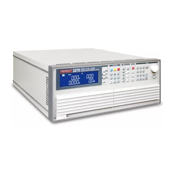
Prodigit 3270 Series Operation Manual (156 pages)
AC/DC High power Electronic Load
Brand:
Prodigit
| Category:
Measuring Instruments
| Size: 7 MB
Table of Contents
Table of Contents
6
Chapter 1 Introduction
10
General Description
10
Fig 1-1 3270 Power Contour
14
Fig 1-2 3271 Power Contour
14
Fig 1-3 3272 Power Contour
14
Fig 1-4 3273 Power Contour
15
Fig 1-5 3274 Power Contour
15
Fig 1-6 Constant Current Mode
15
Fig 1-7 Constant Current Mode
16
Fig 1-8 Constant Resistance Mode
16
Fig 1-9 Constant Voltage Mode
17
Fig 1-10 Constant Power Mode
17
Fig 1-11 Constant Current Mode
18
Fig 1-12 Constant Resistance Mode
18
Fig 1-13 Constant Power Mode
19
Fig 1-14 Constant Voltage Mode
19
Features
20
Standard Accessories
20
Ption
21
Specifications 1
21
Table 1-1 3270 Series Specifications
21
Specifications 2
22
Table 1-1A 3270 Series Specification
23
Chapter 2 Installation
24
Inspection
24
Check Line Voltage
24
Fuse Exchange
24
Fig 2-1 3270 Series AC Input Connection
24
Grounding Requirements
25
Fig 2-2 3270 Series Fuse Holder
25
Environmental Requirements
26
Repair
26
Cleaning
26
Power up
26
Connection to the Load Input Terminal on the Rear Panel
27
Gpib & Rs232 Connection Option
27
Rs232 Connection Option
27
Fig 2-3 3270 Series GPIB & RS232 Connection
27
Fig 2-4 3270 Series RS232 Rear Panel
27
Gpib Connection Option
28
Usb Connection Option
28
Lan Connection Option
28
I/Oconnection
28
Fig 2-5 3270 Series GPIB Rear Panel
28
Fig 2-6 3270 Series USB Connection
28
Fig 2-7 3270 Series LAN Connection
28
Fig 2-8 3270 Series I/O Connection
28
Load Wire Inductance
29
Fig 2-9 Waveform Example: Generate Unstable Oscillation
30
Fig 2-10 Length of Wiring
31
Chapter 3 Operation
32
3270 Series Size Description
32
Fig 3-1 3270 Series SIZE Description
32
3270 Series Panel Diagram
33
Fig 3-2 3270 Series Rear Panel
33
Lcd Display Description
34
Fig 3-3 Typical Connection of 3270 Series Load Module
80
Fig 3-4 Typical Connection of 3270 Series Load Module
80
Fig 3-5 an Equivalent Circuit in Terms of the Current Monitor
81
Fig 3-6 (Correct) Connections to an Oscilloscope
82
Fig 3-7 (Wrong) Connections to an Oscilloscope
82
3270 Series Operating Instructions (1)
83
3270 Series System Operating Instructions (3)
84
Table 3-1
92
Table 3-2 AUTO SEQUENCE 3PH MODE Can Not be Used Command
92
Table 3-3 3PH MODE GLOB Command
92
Fig 3-8 STORE (EDIT) MODE OPERATIONO FLOW-CHART
94
Fig 3-9 TEST MODE OPERATION FLOW-CHA
96
Initial Setting of 3270 Series Load
97
Table 3-4 3270 Initialize
97
Table 3-5 3271 Initialize
97
Table 3-6 3272 Initialize
98
Table 3-7 3273 Initialize
98
Table 3-8 3274 Initialize
99
Protection Features
100
Chapter 4 Remote Control Programming Operation
101
Introduction
101
The Summary of Rs232 Interface and Command
101
Fig 4-1 RS232 INTERFACE CONNECTION of REAR PANEL
102
3270 Series Remote Control Command List1
103
Table 4-1 REMOTE CONTROL SETTING COMMAND SUMMARY
104
Table 4-2 REMOTE CONTROL QUERY COMMAND SUMMARY
105
Table 4-3 REMOTE CONTROL LIMIT COMMAND SUMMARY
105
Table 4-4 STAGE COMMAND SUMMARY
106
Table 4-5 SYSTEM COMMAND SUMMARY
106
Table 4-6 MEASURE COMMAND SUMMARY
107
Table 4-7 Auto Sequence Command List
107
3270 Series Remote Control Command List2
108
Table 4-1B REMOTE CONTROL SETTING COMMAND SUMMARY
108
Table 4-2B REMOTE CONTROL QUERY COMMAND SUMMARY
109
Table 4-3B REMOTE CONTROL LIMIT COMMAND SUMMARY
110
Table 4-4B STAGE COMMAND SUMMARY
111
Table 4-5B SYSTEM COMMAND SUMMARY
112
Table 4-6B MEASURE COMMAND SUMMARY
112
The Description of Abbreviation
113
Remote Control Command Language Description
113
Remote Control Command Description
113
Table 4-8 GPIB COMMAND TERMINATOR
113
Table 4-9 Module for each Series
121
Table 4-10 Register of PROT Status
123
Table 4-11 MODEL NUMBER
124
Chapter 5 Applications
126
Local Sense Connections
126
Fig 5-1 Local Voltage Sense Connections
126
Remote Sense Connections
127
Fig 5-2 Remote Voltage Sense Connections
127
Constant Current Mode and Lin Mode Application
128
Fig 5-3 Constant CURRENT & Mode Application
128
Constant Resistance Mode Application
129
Fig 5-4 Constant Resistance Mode Application
129
Constant Voltage Mode Application
130
Fig 5-5 Constant Voltage Mode Application
130
Constant Power Mode Application
131
Fig 5-6 CONSTANT POWER MODE APPLICATION
132
Battery Discharge Test Application
133
Current Protection Component Test
136
Ac Rectified Load Simulation
138
Parallel Operation
139
Fig 5-7 3270 Series Load Parallel Operation
139
Inrush Current)
140
Fig 5-8 Inrush Current Test at Power on
140
Fig 5-9 Surge Current Test When the Appliance Is Connected
140
Power Supply Ocp Testing
141
Power Supply Opp Testing
143
Short Testing
145
Advertisement
Advertisement
Related Products
Prodigit 34000A Series
Prodigit 34X05A
Prodigit 34X10A
Prodigit 34X15A
Prodigit 34X20A
Prodigit 34X25A
Prodigit 34X30A
Prodigit 34X35A
Prodigit 34X40A
Prodigit 3260A Series
Prodigit Categories
Measuring Instruments
Power Supply
Laboratory Equipment
Motherboard
Control Unit
More Prodigit Manuals
Login
Sign In
OR
Sign in with Facebook
Sign in with Google
Upload manual
Upload from disk
Upload from URL