Table of Contents
Advertisement
Quick Links
Advertisement
Table of Contents

Related Manuals for Prodigit 4016 Series


Summary of Contents for Prodigit 4016 Series
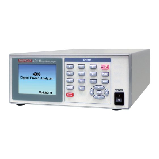
- Page 1 4016 Series Operation manual S/N:900401602 REV:E...
- Page 2 会也可能不会含有所有所列的部件。This table shows where these substances may be found in the supply chain of Prodigit electronic information products, as of the date of sale of the enclosed product. Note that some of the component types listed above may or may not be a part of the enclosed product. ○:表示该有毒有害物质在该部...
- Page 3 Failure to comply with these precautions or with specific warnings elsewhere in this manual violates safety standards of design, manufacture, and intended use of the instrument. PRODIGIT assumes no liability for the customer's failure to comply with these requirements.
- Page 4 DECLARATION OF CONFORMITY Company Name: PRODIGIT ELECTRONICS CO., LTD Address: 8F, No.88, Baojhong Rd., Sindian District, New Taipei City,Taiwan. Declares under sole responsibility that the product as originally delivered Product Names: Digital Power Analyzer Model Numbers: 4016 (And other customized products based upon the above)
- Page 5 SAFETY SYMBOLS Direct current (DC) Alternating current (AC) Both direct alternating Three-phase alternating current Protective earth (ground) On (Supply) Off (Supply) Fuse Caution!Refer to this manual before using the meter. Caution, risk of electric shock CAT IV – Is for measurements performed at the source of the low-voltage installation.
-
Page 6: Table Of Contents
4-5. ···························································· 49 HE DESCRIPTION OF ABBREVIATION 4-6. ···················· 49 OMMUNICATION NTERFACE PROGRAMMING COMMAND DESCRIPTION 4-7. ········· 57 OMMUNICATION NTERFACE PROGRAMMING OMMAND SYNTAX DESCRIPTION Appendix 1 4016 series USB Instruction ······························································ 58 Appendix 2 4016 series LAN Instruction ······························································· 60... - Page 7 Fig 2-5 4016 Series USB interface ·········································································· 8 Fig 3-1 4016 Digital Power Analyzer dimension ····················································· 10 Fig 3-2 4016 Series I/O interface Connection ························································· 10 Fig 3-3 4016 Display panel ·················································································· 11 Fig 3-4 AC Standby power wiring diagram ···························································· 25 Fig 3-5 DC power accumulation wiring diagram ····················································...
- Page 8 Tables Table 1-1 4016 Series Specifications ········································································ 2 Table 1-1A 4016 Series Specification ········································································ 4 Table 4-1 Communication Interface programming setting command summary ················· 48 Table 4-2 GPIB COMMAND TERMINATOR ····························································· 57...
-
Page 10: Chapter 1 Introduction
Harmonic Distortion of Voltage( VTHD) , Voltage Harmonic(VH) 、 Total Harmonic Distortion of Current( ITHD) , Current Harmonic( IH) 1-2. Features The main features of the 4016 series of digital Power Analyzer are highlighted below. 1.2.1. Less than 0.001W standby power measurements meet IEC62301 Energy Star 0.03W standby power. -
Page 11: Specifications 1
1-5. Specifications 1 LINE 100Vac~230Vac ± 10% FREQUENCY 50/60 Hz ±3Hz AC INPUT PROTECT FUSE 0.5A/250V (5*20mm) MAX.POWER 50VA CONSUMPTION Model Voltage Current Dimension(HxWxD) WEIGHT 4016 500V 99.4 mm x 213 mm x 304 mm Table 1-1 4016 Series Specifications... -
Page 12: Specifications 2
4016 Series Operation Manual 3 1-6. Specifications 2 4016 Specification Item Specification 20Vpeak/0.001V 40Vpeak/0.001V 80Vpeak/0.01V Range 200Vpeak/0.01V ACV & DCV 400Vpeak/0.01V Vrms, Vpk+/Vpk-, Vmax/Vmin, V Harmonic 800Vpeak/0.1V Max. Input 800Vpeak/500Vrms ±0.1% of (Reading + Range) Accuracy ±0.5% of (Reading + Range, For Peak) 0.002Apeak/0.1uA... -
Page 13: Table 1-1A 4016 Series Specification
0 ºC to 40 ºC (32 °F to 104 °F) Maximum operating altitude 2000 M (6562 ft) Maximum relative humidity 80% for temperatures up to 31 °C (88 °F) decreasing linearly to 50 % relative humidity at 40 °C (104 °F) Table 1-1A 4016 Series Specification... -
Page 14: Chapter 2 Installation
Prodigit's sales and service office or representative. You’re 4016 Series AC/DC Digital Power Analyzer was shipped with a power cord for the type of Terminal blocks used at your location. If the appropriated cord was not included, please contact your nearest Prodigit sales office to obtain the correct cord. -
Page 15: Grounding Requirements
2-4 Grounding requirements SHOCK HAZARD 1. It is requested to use the 3Pin plug connector only for 4016 Series mainframe to out of danger when electric leakage. And the complete and proper grounded is necessary. 2. The 4016 Series high power AC/DC Digital Power Analyzer is equipped with three conductor cable which plugs in an appropriate receptacle to ground the instrument's cover. -
Page 16: Environmental Requirements
2-6 Repair If the instrument is damaged, please attach a tag to the instrument to identify the owner and indicated the require service or repairing. And inform the Prodigit sales and service office or representative. Fuses (F1, F2, Fuse 25A), overcurrent protection diodes (D1~4, D31~32) and switching components (14016402) are consumables and are not covered by the warranty. -
Page 17: Rs232 Interface Option
Of devices connected together, up to 20 meters maximum. Fig 2-4 4016 Series GPIB interface 2-12 USB interface option Fig 2-5 shows the USB interface in the rear panel of 4016 Series Digital Power Analyzer . Please Refer Appendix B. Fig 2-5 4016 Series USB interface... -
Page 18: Chapter 3 Operation
4016 Series Operation Manual 9 Chapter 3 Operation This chapter describes the front panel function and operation of each 4016 Series Digital Power Analyzer, The communication Interface programming is described in Chapter 4. 3-1. 4016 Series dimension description... -
Page 19: 4016 I/Ointerface Function
10 PRODIGIT Fig 3-1 4016 Digital Power Analyzer dimension 3-2. 4016 I/O interface function The 4016 Series Digital Power Analyzer I/O interface includes Vsense, Load, Source, SYNC TTL, and EXT. Fig 3-2 4016 Series I/O interface Connection Power Input 100~230V 50/60Hz... -
Page 20: Operating Instructions
4016 Series Operation Manual 11 3-3. Operating instructions: Fig 3-3 4016 Display panel • Model number (1) Refers to model number, of 4016 Series Digital Power Analyzer. • 4016 Power switch (2) • Number keys (3) • Key (4), Turn output on or off. - Page 21 12 PRODIGIT 3.3.1. In the 4016 series, there are 0~7 kinds of available numeric keys to choose from. The Program is as follows: 0.System 1.Meter Mode 2.Harmonic Mode 3.Inrush Current 4.AC Whr Standby Power 5.DC Ahr/Whr Accumulator ...
- Page 22 4016 Series Operation Manual 13 • Sampling cycle average setting Press the up or down keys to Average, press the select key to enter the edit. Press the up, down, left, right keys to editing data, range from 1 to 64 Cycles; press the select key to store the data.
- Page 23 14 PRODIGIT Press the up, down, left, right keys to edit, press the select key to save the data. • Switch off angle setting Press the up or down keys to Off Degree, press the select key to enter the edit.
- Page 24 4016 Series Operation Manual 15 • External Input Scale rate adjustment Press the up or down keys to Ext Input scale, press the select key to enter the edit. Press the up, down, left, right keys to edit the data, press the select key to save the data, scale range from 1 to 10000.
- Page 25 16 PRODIGIT Press the On/Off key to turn the output on or off. Press the up or down key to switch the display item. ※ The display order is: Vrms→Arms→Watt→PF→VTHD→ITHD→VA→Freq→Vpk+→ Vpk-→Vmax→Vmin→Apk+→Apk-→Amax→Amin→Wmax→Wmin→VAR→VCF→ ICF。 • Switch display measurement data and waveform ...
- Page 26 4016 Series Operation Manual 17 • Meter Mode Setting Press the Edit key to enter the Meter Mode Setting page. Press the up or down key to Auto VRange, Press the left or right key to set On or Off.
- Page 27 18 PRODIGIT Press the up or down key to V_Range, Press the left or right key to set Voltage Range. Press the up or down key to Auto IRange, Press the left or right key to set On or Off.
- Page 28 4016 Series Operation Manual 19 Press the up or down key to move the display item you want to modify. Select the open display item; press the select key to close the display item (the closed item will automatically move to the end of the page).
- Page 29 20 PRODIGIT 3.3.4. Harmonic measurement mode • Harmonic measurement mode Press the number key 2 under the Menu page mode to enter the harmonic measurement mode. Press the On/Off key to turn the output on or off. Press the up or down key to switch display the harmonic level page.
- Page 30 4016 Series Operation Manual 21 • Harmonic graphic display Press the Graph key to switch data or graphic display When the harmonic graphic is displayed, press the up or down key to switch between the V&A, V, and A harmonic patterns.
- Page 31 22 PRODIGIT When the harmonic graphic is displayed, press the left or right key to switch to display the harmonic level value. 3.3.5. Inrush voltage and current measurement • Inrush voltage measurement mode Press the number key 3 under the Menu page mode to enter the inrush voltage and current measurement mode.
- Page 32 4016 Series Operation Manual 23 Press the up or down key to move the modified option. • Graphic shift setting Press the up or down key to Graph Scroll, press the select key to enter the edit graphic shift setting, Graph scroll range form 0~100ms.
- Page 33 24 PRODIGIT • Voltage measurement gear setting Press the up or down key to V_Range, press the left or right key to switch the set voltage position. • Current measurement gear setting Press the up or down key to I_Range, press the left or right key to switch the set current position.
- Page 34 4016 Series Operation Manual 25 • Output close angle setting Press the up or down key to OFF Degree, press the select key to enter the closing angle setting. Press the up or down key to edit the closing angle, press the select key to save the setting angle.
- Page 35 26 PRODIGIT Press the number key 4 under the Menu page to enter the AC standby power measurement mode. When the output is off, press the On/Off key to start accumulating power consumption. When the output is turned on, press the On/Off key to stop the accumulated power consumption.
- Page 36 4016 Series Operation Manual 27 • AC standby power setting page On the AC Standby Power page, press the Edit key to enter the AC Standby Power Settings page. Press the up or down key to move to the option you want to modify.
- Page 37 28 PRODIGIT • Automatic upshift setting Press the up or down key to Range_AutoUp, press the left or right key to change the setting to turn the automatic upshift function on or off. ※ When this function is turned on, it will automatically rise to the next gear when the voltage or current exceeds the set gear position.
- Page 38 4016 Series Operation Manual 29 3.3.7. DC power cumulative measurement • DC power accumulation measurement mode DC power accumulation wiring diagram Fig 3-5 DC power accumulation wiring diagram Press the number key 5 under the Menu page to enter the DC power cumulative...
- Page 39 30 PRODIGIT When the output is off, press the On/Off key to start accumulating power Consumption. When the output is turned on, press the On/Off key to stop the accumulated power consumption. • DC average current, power graph ...
- Page 40 4016 Series Operation Manual 31 Press the up or down key to move to the option you want to modify. • Voltage gear setting Press the up or down key to V_Range, press the left or right key to switch the set voltage position.
- Page 41 32 PRODIGIT • Counting function Press the up or down key to Count Mode, press the left or right key to switch the setting count setting. ※ None=Off count, Up=Time positive, Down=Time countdown. Press the up, down key to xxHr xxMin xxSec, press the select key to enter the counting time setting.
- Page 42 4016 Series Operation Manual 33 Press the On/Off key to start or end the data measurement record. • Measurement data record setting Press the Edit key to enter the measurement data record setting. • Measurement data record setting ...
- Page 43 34 PRODIGIT • Current gear setting Press the up or down key to I_Range, press the left or right key to switch the current gear. • Automatic upshift setting Press the up or down key to Range_AutoUp, press the left or right key to turn the function on or off.
- Page 44 4016 Series Operation Manual 35 • Switch cycle test mode Press the number key 7 under the Menu page to enter the switch cycle test. Press the On/Off key to start the test. Press the up or down key to change between displaying the immediate value or the Average value.
- Page 45 36 PRODIGIT Press the left or right key to switch to display the Nth test value (the data retains the last 256 tests). • Switch cycle test setting Press the Edit key to enter the switch cycle test setup page.
- Page 46 4016 Series Operation Manual 37 Press the up, down, left, right keys to modify the value, press the select key to save the set value. • Switch off angle setting Press the up or down key to Off Degree, press the select key to enter the setting switch closing angle.
- Page 47 38 PRODIGIT Press the up, down, left, right keys to modify the value, press the select key to save the set value. • Switch off hold time setting Press the up or down key to Off Time, press the select key to enter the setting switch to turn off the hold time.
- Page 48 4016 Series Operation Manual 39 Press the up, down, left, right keys to modify the value, press the select key to save the set value. • Voltage gear setting Press the up or down key to V_Range, press the left or right key to switch the setting position.
-
Page 49: External Current Measurement Wiring Diagram
40 PRODIGIT 3-4. External current measurement wiring diagram 3.4.1. Series resistance partial pressure measurement current AC Load output AC Source output <=2.5Vpea 4016 Fig 3-6 Series resistance partial pressure wiring diagram 3.4.2. CT measurement current wiring diagram AC Source output AC Load output <=2.5Vpeak... - Page 50 4016 Series Operation Manual 41 3.5.1. Three-phase measurement wiring connection diagram Fig 3-8 4016 three-phase four-wire Y connection 3 sets of electricity meter wiring diagram...
- Page 51 42 PRODIGIT 3.5.2. Three-phase three-wire△ connection three groups of meter connection Fig 3-9 4016 three-phase three-wire △ connected to three sets of electricity meter wiring diagram...
-
Page 52: Fig 3-10 4016 Three-Phase Three-Wire △ Connected To Two Sets Of Meter Diagram
4016 Series Operation Manual 43 3.5.3. Three-phase three-wire △ connection Two groups of meter connection Fig 3-10 4016 three-phase three-wire △ connected to two sets of meter diagram... -
Page 53: Chapter 4 Communication Interface Programming Operation
PC or NOTEBOOK PC with Communication Interface programming; you can use an application such as high-level syntax C and VB to form an automatic control system. NOTE: When use USB interface controls the 4016 Series, the 4016 Series will convert the USB interface to RS232 interface. -
Page 54: Fig 4-1 Rs232 Interface Connection Of Rear Panel
4016 Series Operation Manual 45 Abbreviation Description Pin1 Carrier Detect Pin2 Receive Pin3 Transmit Pin4 Data Terminal Ready Pin5 Ground Pin6 Data Set Ready Pin7 Request To Send Pin8 Clear To Send Pin9 Ring Indicator Fig 4-1 RS232 INTERFACE CONNECTION OF REAR PANEL... -
Page 55: 4016 Series Communication Interface Programming Command List
46 PRODIGIT 4-4. 4016 Series Communication Interface programming command list COMMAND RETURN 備註 MEAS:VRMS?{; | NL} ###.###V MEAS:VPEAK?{; | NL} ###.###V,###.###V MEAS:VMAXMIN?{; | NL} ###.###V,###.###V MEAS:IRMS?{; | NL} ###.####(uA | mA | A) MEAS:IPEAK?{; | NL} ###.####(uA | mA | A),###.####(uA | mA | A) MEAS:IMAXMIN?{;... - Page 56 4016 Series Operation Manual 47 COMMAND RETURN 備註 OUT?{; | NL} ON | OFF 0=OFF,1=ON MODE?{; | NL} AC | DC 0=Menu,1=Meter,2=Harmonic,3=Inrush METER?{; | NL} ,4=AC Standby,5=DC Accumuloator 6=DataLog,7=On/Off Cycling 1=20V,2=40V,3=80V,4=200V, VRANG?{; | NL} 5=400V,6=800V 1=2mA,2=4mA,3=8mA,4=20mA, 5=40mA,6=80mA,7=0.2A,8=0.4A, IRANG?{; | NL} 1~18 9=0.8A,10=2A,11=4A,12=8A,13=10A...
-
Page 57: Table 4-1 Communication Interface Programming Setting Command Summary
48 PRODIGIT COMMAND 備註 OUT {SP}{0 | 1 | ON | OFF} {; | NL} Set Output MODE{SP}{0 | 1 | AC | DC}{; | NL} Set AC/DC Mode METER{SP}{0~7}{; | NL} Set Meter Mode VRANG{SP}{0~6}{; | NL} Set VRange IRANG{SP}{0~18}{;... -
Page 58: The Description Of Abbreviation
4016 Series Operation Manual 49 4-5. The description of abbreviation SP:Space, the ASCII code is 20 Hexadecimal. ;:Semicolon, Program line terminator, the ASCII code is OA Hexadecimal. NL:New line, Program line terminator, the ASCII code is OA Hexadecimal. NR2:Digits with decimal point. It can be accepted in the range and format of ###.#####. - Page 59 50 PRODIGIT Syntax: MEAS: VA? {; | NL} Description: Read power. VAR? Syntax: MEAS: VAR? {; | NL} Description: Read measurement invalid power. Syntax: MEAS: PF? {; | NL} Description: Reading measurement power factor. VCF ? Syntax: MEAS: VCF? {; | NL} Description: Read measurement voltage peak factor.
- Page 60 4016 Series Operation Manual 51 KWH? Syntax: MEAS: KWH? {; | NL} Description: Read accumulated watt hour value. AVGWATT? Syntax: MEAS: AVGWATT? {; | NL} Description: Reading watt average. ELT? Syntax: MEAS: ELT? {; | NL} Description: Read elapsed time.
- Page 61 52 PRODIGIT The starting point of the graphic data is random, not starting from 0 degrees I GRAPH? (For RS232 or USB Interface only) Syntax: MEAS: IGRAPH?{; | NL} Description: 3bytes x4096(Current Graph) +0x0D 0x0A The 1st highest bit is positive and negative flag, 0=positive value 1=negative value, the value contains decimal place, and the decimal place is determined according to the current gear position (please refer to 1.6 Specifications)
- Page 62 4016Series Operation Manual 53 4.6.2. Read set value OUT? Syntax: OUT? {; | NL} Description: output status? Return: ON, OFF MODE? Syntax: MODE? {; | NL} Description: setting AC and DC mode? Return: AC, DC METER? Syntax: METER? {; | NL} Description: usage model? Return:0=Menu,1=Meter,2=Harmonic,3=Inrush,4=AC Standby,5= DC Accumulator 6=DataLog,7=On/Off Cycling...
- Page 63 Syntax: VERsion? {; | NL} Description: Firmware version? Return: r#. ##,r#,r# *IDN? Syntax: *IDN? {; | NL} Description: Model name? Return: PRODIGIT: 4016 ONTIME? Syntax: ONTIME?{; | NL} Description: Ask the switch to turn on the hold time setting? Return: ###. ### (Sec) OFFTIME? Syntax: OFFTIME?{;...
- Page 64 4016 Series Operation Manual 55 4.6.3. Control Setting Command Syntax: OUT {SP}{0|1} {; | NL} Description: Set switch on or off Return: 0: OFF, 1: ON MODE Syntax: MODE {SP} {0|1|AC|DC} {; | NL} Description: Set AC and DC measurement mode...
- Page 65 56 PRODIGIT GRAPHT Syntax: GRAPHT {SP} {0~100} {; | NL} Description: Set the Inrush current measurement mode waveform displacement time Return: Setting range 0~100.00ms. REMote Syntax: REMote {; | NL} Description: Set to remote control lock button LOCAL Syntax: LOCAL {; | NL}...
-
Page 66: Ommunication Nterface Programming Ommand Syntax Description
4016Series Operation Manual 57 4-7. Communication Interface programming Command syntax description { } : The contents of the { } symbol must be used as a part or data of the GPIB command, it cannot be omitted. [ ] : The contents of the [ ] symbol indicts the command can be used or not. It depends on the testing application. -
Page 67: Appendix 1 4016 Series Usb Instruction
58 PRODIGIT Appendix 1 4016 series USB Instruction 1. Install the USB DRIVER select USB\SETUP\PL-2303 Driver Installer.exe... - Page 68 4016 Series Operation Manual 59 2. After the installation, connect the 4016 series and PC with USB. Then select the item USB to Serial Port (COM3), set the BAUD-RATE and Flow control to 115200bps and Hardware to control 4016 series with COM3.
-
Page 69: Appendix 2 4016 Series Lan Instruction
60 PRODIGIT Appendix 2 4016 series LAN Instruction Connect the 4016 to the power supply, connect to the lan cable, and connect the other end of the network route to the HUB hub. Please execute IPScanner.EXE in the LAN directory on the CD. Windows security alert will appear first. - Page 70 4016Series Operation Manual 61 Please press Device Setting, the following screen will appear. Please enter the relevant settings : IP Address : Subnet Mask : iii. Gateway Address : Network link speed : (AUTO) DHCP client : Dynamic IP setting, the default value is Disable, unless the DHCP Server can change the setting to Enable Socket port of HTTP setup : The default is 80, no need to set vii.
Need help?
Do you have a question about the 4016 Series and is the answer not in the manual?
Questions and answers