
Related Manuals for ProSoft Technology inRax MVI69-PDPMV1


Summary of Contents for ProSoft Technology inRax MVI69-PDPMV1
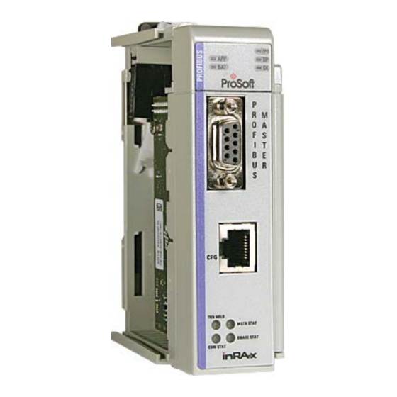
- Page 1 MVI69-PDPMV1 CompactLogix or MicroLogix Platform PROFIBUS DPV1 Master July 8, 2011 USER MANUAL...
-
Page 2: Your Feedback Please
® ProSoft Technology Product Documentation In an effort to conserve paper, ProSoft Technology no longer includes printed manuals with our product shipments. User Manuals, Datasheets, Sample Ladder Files, and Configuration Files are provided on the enclosed CD-ROM in ® Adobe Acrobat Reader file format (.PDFs). -
Page 3: Important Installation Instructions
Important Installation Instructions Power, Input, and Output (I/O) wiring must be in accordance with Class I, Division 2 wiring methods, Article 501-4 (b) of the National Electrical Code, NFPA 70 for installation in the U.S., or as specified in Section 18-1J2 of the Canadian Electrical Code for installations in Canada, and in accordance with the authority having jurisdiction. -
Page 4: Battery Life Advisory
Battery Life Advisory The MVI46, MVI56, MVI56E, MVI69, and MVI71 modules use a rechargeable Lithium Vanadium Pentoxide battery to backup the real-time clock and CMOS. The battery should last for the life of the module. The module must be powered for approximately twenty hours before the battery becomes fully charged. After it is fully charged, the battery provides backup power for the CMOS setup and the real-time clock for approximately 21 days. -
Page 5: Table Of Contents
Disabling the RSLinx Driver for the Com Port on the PC ........71 Downloading the Project to the Module Using CIPconnect ........73 3.5.1 Example........................75 ProSoft Technology, Inc. Page 5 of 225 July 8, 2011... - Page 6 5.6.4 Byte 3 - Master Address ..................156 5.6.5 Byte 4 - Ident Number High .................. 156 5.6.6 Byte 5 - Ident Number Low ................... 156 Page 6 of 225 ProSoft Technology, Inc. July 8, 2011...
- Page 7 6.3.4 MVI69 Input and Output Data Blocks ..............167 PROFIBUS comDTM .................... 184 6.4.1 ProSoft Technology Product Availability ............... 185 6.4.2 Introduction to PROFIBUS comDTM ..............185 6.4.3 Installation ......................189 ...
- Page 8 Contents MVI69-PDPMV1 ♦ CompactLogix or MicroLogix Platform User Manual PROFIBUS DPV1 Master Page 8 of 225 ProSoft Technology, Inc. July 8, 2011...
-
Page 9: Guide To The Mvi69-Pdpmv1 User Manual
Product Specifications Product Specifications (page 157) Support, Service, and Support, Service This section contains Support, Service and Warranty and Warranty (page Warranty information. 213) Index Index of chapters. Index ProSoft Technology, Inc. Page 9 of 225 July 8, 2011... - Page 10 Guide to the MVI69-PDPMV1 User Manual MVI69-PDPMV1 ♦ CompactLogix or MicroLogix Platform User Manual PROFIBUS DPV1 Master Page 10 of 225 ProSoft Technology, Inc. July 8, 2011...
-
Page 11: Start Here
Hardware installation and wiring: install the module, and safely connect PROFIBUS DPV1 and CompactLogix or MicroLogix devices to a power source and to the MVI69-PDPMV1 module’s application port(s) ProSoft Technology, Inc. Page 11 of 225 July 8, 2011... -
Page 12: System Requirements
HyperTerminal or other terminal emulator program capable of file transfers using Ymodem protocol. NOTE: MVI69/PS69 modules will not work with CompactLogix L4x processors using RSLogix 5000 v17. All other processor combinations and RSLogix versions will work correctly. Page 12 of 225 ProSoft Technology, Inc. July 8, 2011... -
Page 13: Package Contents
Cable Cable #14, RJ45 to For DB9 Connection to Module’s Port DB9 Male Adapter cable If any of these components are missing, please contact ProSoft Technology Support for replacement parts. ProSoft Technology, Inc. Page 13 of 225 July 8, 2011... -
Page 14: Installing Prosoft Configuration Builder Software
You must install the ProSoft Configuration Builder (PCB) software to configure the module. You can always get the newest version of ProSoft Configuration Builder from the ProSoft Technology website. To install ProSoft Configuration Builder from the ProSoft Technology website Open your web browser and navigate to http://www.prosoft- technology.com/pcb... -
Page 15: Setting Jumpers
Note: If you are installing the module in a remote rack, you may prefer to leave the Setup pins jumpered. That way, you can update the module’s firmware without requiring physical access to the module. ProSoft Technology, Inc. Page 15 of 225 July 8, 2011... -
Page 16: Installing The Module
Move the module back along the tongue-and-groove slots until the bus connectors on the MVI69 module and the adjacent module line up with each other. Page 16 of 225 ProSoft Technology, Inc. July 8, 2011... - Page 17 Push the module’s bus lever back slightly to clear the positioning tab and move it firmly to the left until it clicks. Ensure that it is locked firmly in place. Close all DIN-rail latches. ProSoft Technology, Inc. Page 17 of 225 July 8, 2011...
- Page 18 MVI69-PDPMV1 ♦ CompactLogix or MicroLogix Platform User Manual PROFIBUS DPV1 Master Press the DIN-rail mounting area of the controller against the DIN-rail. The latches will momentarily open and lock into place. Page 18 of 225 ProSoft Technology, Inc. July 8, 2011...
-
Page 19: Ladder Logic
The sample ladder logic, on the inRAx CD-ROM, is extensively commented, to provide information on the purpose and function of each rung. For most applications, the sample ladder will work without modification. ProSoft Technology, Inc. Page 19 of 225 July 8, 2011... -
Page 20: Mvi69-Pdpmv1 Sample Add-On Instruction Import Procedure
MVI69-PDPMV1 module to act as a PROFIBUS Acyclic Class 2 Master. Class 2 sample ladder currently available only for Backplane Transfer Size of 240. Page 20 of 225 ProSoft Technology, Inc. July 8, 2011... -
Page 21: Creating A New Rslogix5000 Project
User Manual 2.1.1 Creating a New RSLogix5000 Project Open the F menu, and then choose N Select Revision 16. 2.1.2 Creating the Module Right-click I/O C and choose N ONFIGURATION ODULE ProSoft Technology, Inc. Page 21 of 225 July 8, 2011... - Page 22 PDPMV1 module will be installed. Input Assembly Instance Input Size 62 / 122 / 242 Output Assembly Instance Output Size 61 / 121 / 241 Configuration Assembly Instance Configuration Size Page 22 of 225 ProSoft Technology, Inc. July 8, 2011...
- Page 23 Important: You must set the Block Transfer Size in ProSoft Configuration Builder to match the block size for the Add-On Instruction, otherwise the module may not function correctly. On the C tab, check or un-check, as desired the Major fault option. ONNECTION ProSoft Technology, Inc. Page 23 of 225 July 8, 2011...
-
Page 24: Importing The Ladder Rung
Add-On Instruction. Select an empty rung in the new routine, and then click the right mouse button to open a shortcut menu. On the shortcut menu, choose I MPORT Page 24 of 225 ProSoft Technology, Inc. July 8, 2011... - Page 25 The following window will be displayed showing the controller tags to be created during the import procedure: If desired, the description, "MVI69- PDPMV1 Interface AOI" may be typed into the description field for AOI69PDPMV1_60.L5X file. ProSoft Technology, Inc. Page 25 of 225 July 8, 2011...
- Page 26 1 of the local rack, this step is not required. Click OK to confirm the import. RSLogix will indicate that the import is in progress: Page 26 of 225 ProSoft Technology, Inc. July 8, 2011...
- Page 27 Add-On Instruction, otherwise the module may not function correctly. The procedure has also imported new user-defined data types, data objects and the Add-On Instruction to be used at your project. ProSoft Technology, Inc. Page 27 of 225 July 8, 2011...
-
Page 28: Adding Multiple Modules (Optional)
Block Transfer Sizes. In the I/O C folder, click the right mouse button to open a ONFIGURATION shortcut menu, and then choose N ODULE Select 1769-MODULE. Page 28 of 225 ProSoft Technology, Inc. July 8, 2011... - Page 29 ROGRAM menu. On the shortcut menu, choose N OUTINE In the New Routine dialog box, enter the name and description of your routine, and then click OK. ProSoft Technology, Inc. Page 29 of 225 July 8, 2011...
- Page 30 Note: It is not necessary to create a completely new routine. It is possible to add the MVI69- PDPMV1_2 module in the previously created routine. If you need to create a new routine, insert a jump instruction in the previous routine to the new routine. Page 30 of 225 ProSoft Technology, Inc. July 8, 2011...
- Page 31 Select the AOI69PDPMV1_60.L5X file for the block size you selected for the module (60, 120 or 240). 10 The following window will be displayed showing the tags to be imported: ProSoft Technology, Inc. Page 31 of 225 July 8, 2011...
- Page 32 12 Change the default tags AOI69PDPMV1 and MVI69PDPMV1 to avoid conflict with existing tags. In this step, you should append a string to the default tag names, such as "_2", as shown in the following illustration. Page 32 of 225 ProSoft Technology, Inc. July 8, 2011...
- Page 33 MVI69-PDPMV1 ♦ CompactLogix or MicroLogix Platform Ladder Logic PROFIBUS DPV1 Master User Manual 13 You will be prompted to confirm your change. Click OK to continue. ProSoft Technology, Inc. Page 33 of 225 July 8, 2011...
- Page 34 Main routine with a JSR instruction to the new routine to enable the PLC logic to communicate with both modules. The setup procedure is now complete. Save the project and download the application to your CompactLogix processor. Page 34 of 225 ProSoft Technology, Inc. July 8, 2011...
-
Page 35: Connecting Your Pc To The Processor
Connect the right-angle connector end of the cable to your controller at the communications port. Connect the straight connector end of the cable to the serial port on your computer. ProSoft Technology, Inc. Page 35 of 225 July 8, 2011... -
Page 36: Downloading The Sample Program To The Processor
Click OK to switch the processor from PROGRAM mode to RUN mode. Note: If you receive an error message during these steps, refer to your RSLogix documentation to interpret and correct the error. Page 36 of 225 ProSoft Technology, Inc. July 8, 2011... - Page 37 Note: If the list of configured drivers is blank, you must first choose and configure a driver from the Available Driver Types list. The recommended driver type to choose for serial communication with the processor is RS-232 DF1 Devices. ProSoft Technology, Inc. Page 37 of 225 July 8, 2011...
- Page 38 If you are still unable to auto-configure the port, refer to your RSLinx documentation for further troubleshooting steps. Page 38 of 225 ProSoft Technology, Inc. July 8, 2011...
-
Page 39: Adding The Module To An Existing Compactlogix Project
Controller Organization window to ONFIGURATION display a pop-up menu. Select the N option from the I/O ODULE menu. ONFIGURATION This action opens the Select Module dialog box: ProSoft Technology, Inc. Page 39 of 225 July 8, 2011... - Page 40 Data - INT Slot The slot number in the rack where the module is installed Input Assembly Instance Input Size Output Assembly Instance Output Size Configuration Assembly Instance Configuration Size Page 40 of 225 ProSoft Technology, Inc. July 8, 2011...
- Page 41 Data - INT Slot The slot number in the rack where the module is installed Input Assembly Instance Input Size Output Assembly Instance Output Size Configuration Assembly Instance Configuration Size ProSoft Technology, Inc. Page 41 of 225 July 8, 2011...
- Page 42 Copy the controller tags from the sample program. 10 Copy the ladder rungs from the sample program. 11 Save and download (page 36) the new application to the controller and place it in RUN mode. Page 42 of 225 ProSoft Technology, Inc. July 8, 2011...
-
Page 43: Adding The Module To An Existing Micrologix Project
"Other" type IO card dialog box. Enter the values shown in the following illustration to define the module correctly for the MicroLogix processor, and then click OK to save your configuration. ProSoft Technology, Inc. Page 43 of 225 July 8, 2011... - Page 44 Download the new application to the controller and place the processor in RUN mode. If you encounter errors, refer to Diagnostics and Troubleshooting (page 133) for information on how to connect to the module's Config/Debug port to use its troubleshooting features. Page 44 of 225 ProSoft Technology, Inc. July 8, 2011...
-
Page 45: Module Setup
PROFIBUS cable, allowing the PROFIBUS cable to connect without interfering with cables connected to the Configuration/Debug port on the module. Refer to the following illustration for the correct cabling configuration. ProSoft Technology, Inc. Page 45 of 225 July 8, 2011... -
Page 46: Connecting Your Pc To The Module
Connect the RJ45-DB-9 Serial Adapter Cable to the Null Modem Cable. Insert the RJ45 cable connector from the RJ45-DB-9 cable into the Configuration/Debug port of the module. Attach the other end to the serial port on your PC. Page 46 of 225 ProSoft Technology, Inc. July 8, 2011... -
Page 47: Configuring The Module
MVI69-PDPMV1 ♦ CompactLogix or MicroLogix Platform Module Setup PROFIBUS DPV1 Master User Manual Configuring the Module ProSoft Technology has provided a configuration tool called ProSoft Configuration Builder (PCB) that will help you with the following tasks: Creating a configuration project ... - Page 48 In the Product Line Filter area of the dialog box, select MVI69. In the Select Module Type dropdown list, select MVI69-PDPMV1, and then click OK to save your settings and return to the ProSoft Configuration Builder window. Page 48 of 225 ProSoft Technology, Inc. July 8, 2011...
-
Page 49: Setting Module Parameters
Click the plus sign [+] next to the module to expand the module tree, and then expand the MVI69 PDPM-V1 tree. Double-click the MVI PROFIBUS M DPV1 object. This action opens the ASTER Edit dialog box. ProSoft Technology, Inc. Page 49 of 225 July 8, 2011... - Page 50 Select the object, and then click the right mouse button to open a shortcut menu. From the shortcut menu, choose R ENAME Type the name to assign to the object. Click away from the object to save the new name. Page 50 of 225 ProSoft Technology, Inc. July 8, 2011...
-
Page 51: Configuring The Profibus Master
This action opens the ProSoft Configuration Builder for PROFIBUS application. Click [+] to expand the PROFIBUS Master tree. Drag the PROFIBUS Master icon into the Bus Configuration window. This is automatically done by the software for new applications. ProSoft Technology, Inc. Page 51 of 225 July 8, 2011... - Page 52 Note: The PROFIBUS tab contains the address setting and advanced configuration settings for the Master. The default settings on this tab work best in most applications. Click OK to save your changes and return to the Bus Configuration window. Page 52 of 225 ProSoft Technology, Inc. July 8, 2011...
-
Page 53: Installing The Gsd Files
Use the File / Open dialog box to browse for the location of the image file to use. Tip: GSD configuration files for popular PROFIBUS slaves and ProSoft Technology modules are included with the installation. If you have other GSD files for your PROFIBUS slaves, copy them into C:\Documents and Settings\All Users\Application Data\ProSoft\GSD (Windows XP / 2000) or C:\My Documents\ (Windows 98) and ProSoft Configuration Builder will load them automatically. - Page 54 When the window is closed the network scan will be omitted. When a network scan is initiated, the PROFIBUS Master Configuration window will download the Master bus parameters (baudrate etc.). Page 54 of 225 ProSoft Technology, Inc. July 8, 2011...
- Page 55 2. Send FB_APPL_GET_SLAVE_DIAG (external request) to all devices identified as slaves according to the Live list. 3. Send FB_APPL_GET_SLAVE_CONFIG to all devices identified as slaves according to the Live list. ProSoft Technology, Inc. Page 55 of 225 July 8, 2011...
- Page 56 The other compatible files should be stored so that the user can select one of them instead. If the user selects another GSD-file, the PROFIBUS Master Configuration window will run through the Module Selection Algorithm (described below) again. Page 56 of 225 ProSoft Technology, Inc. July 8, 2011...
- Page 57 DOPT SELECTED SLAVES Address In this column the node address of the slaves will be displayed. Found slaves should be listed in ascending order according to their node addresses. ProSoft Technology, Inc. Page 57 of 225 July 8, 2011...
- Page 58 The check box in the Select column will be grayed out. Page 58 of 225 ProSoft Technology, Inc. July 8, 2011...
- Page 59 Set Slave dialog box. The check box in the Select column will be marked allowing the user to adopt the slave to the configuration. ProSoft Technology, Inc. Page 59 of 225 July 8, 2011...
- Page 60 SlaveDiag mailbox message. If there are more files with the same Ident number in the device catalog, the first matching GSD-file will be displayed in blue color in a drop-down list. Page 60 of 225 ProSoft Technology, Inc. July 8, 2011...
- Page 61 If no slaves are found a message similar to the one below will appear. The same message will also show up if no slaves are found during the initial scan (for example when selecting S from the Online menu). CAN NETWORK ProSoft Technology, Inc. Page 61 of 225 July 8, 2011...
- Page 62 Also observe the configuration for the very same slave at the bottom of the screen. Note: Slave is equal to the Ident number and that the Device path and Order number/designation fields are left empty. Page 62 of 225 ProSoft Technology, Inc. July 8, 2011...
- Page 63 [+] to expand the folder. Drag the slave icon into the Bus Configuration window. The slave device appears in the Bus Configuration window as a network location to the Master. ProSoft Technology, Inc. Page 63 of 225 July 8, 2011...
- Page 64 Drag the input and output parameters to the slot location grid below the Bus Configuration window. This view displays the configuration data, order number, and starting input and output addresses. Page 64 of 225 ProSoft Technology, Inc. July 8, 2011...
- Page 65 Repeat steps 2 through 6 for all slaves you intend to place on the network. When you are finished adding slaves, open the P menu and choose ROJECT to return to the Master Setup dialog box. ProSoft Technology, Inc. Page 65 of 225 July 8, 2011...
-
Page 66: Calculating The Checksums
The inRAx Data Type dialog box uses the information about your PROFIBUS Master and slaves to display the data types you configured. You will need this information to determine the memory areas your application will use in the CompactLogix processor. Page 66 of 225 ProSoft Technology, Inc. July 8, 2011... - Page 67 RSLogix. The sample ladder logic contains input and output arrays that must be cross-referenced with the variables. The next step is to download the project to the MVI69 module. ProSoft Technology, Inc. Page 67 of 225 July 8, 2011...
-
Page 68: Backing Up The Project
A complete backup consists of the Project and Master Configuration files, plus the GSD configuration files. The default location for the GSD files is C:\Documents and Settings\All Users\Application Data\ProSoft\GSD (Windows XP / 2000) or C:\My Documents\. Page 68 of 225 ProSoft Technology, Inc. July 8, 2011... - Page 69 Having all the files for your PCB configuration stored in one folder makes it easier to transfer the application from one system to the other or to send your files to ProSoft Technical Support when you need assistance. ProSoft Technology, Inc. Page 69 of 225 July 8, 2011...
-
Page 70: Downloading The Project To The Module Using A Serial Com Port
The module will perform a platform check to read and load its new settings. When the platform check is complete, the status bar in the Download dialog box will display the message Module Running. Page 70 of 225 ProSoft Technology, Inc. July 8, 2011... -
Page 71: Disabling The Rslinx Driver For The Com Port On The Pc
1. If the network is being browsed, then you will not be able to stop this driver. To stop the driver your RSWho screen should look like this: Branches are displayed or hidden by clicking on the or the icons. ProSoft Technology, Inc. Page 71 of 225 July 8, 2011... - Page 72 (usually only on Windows NT machines). If you have followed all of the above steps, and it will not stop the driver, then make sure you do not have RSLogix open. If RSLogix is not open, and you still cannot stop the driver, then reboot your PC. Page 72 of 225 ProSoft Technology, Inc. July 8, 2011...
-
Page 73: Downloading The Project To The Module Using Cipconnect
Each row in the CIPconnect Path Editor corresponds to a physical rack in the CIP path. Since bridging through multiple racks is not supported in the MVI69- PDPMV1, only one row is needed for configuring the CIP path. ProSoft Technology, Inc. Page 73 of 225 July 8, 2011... - Page 74 ONSTRUCT Click OK to confirm the configured path. The following example should provide a better understanding on how to set up the path for your network. Page 74 of 225 ProSoft Technology, Inc. July 8, 2011...
-
Page 75: Example
IP=192.168.0.100 MVI69-PDPMV1 In the Download window, click CIP P Configure the path as shown in the following illustration, and click CIP P to build the path in text format. ONSTRUCT ProSoft Technology, Inc. Page 75 of 225 July 8, 2011... - Page 76 Module Setup MVI69-PDPMV1 ♦ CompactLogix or MicroLogix Platform User Manual PROFIBUS DPV1 Master Check the new path in the Download dialog box. Page 76 of 225 ProSoft Technology, Inc. July 8, 2011...
- Page 77 The ONNECTION following message should be displayed upon success. Click D to download the configuration files to the module through OWNLOAD the path. ProSoft Technology, Inc. Page 77 of 225 July 8, 2011...
- Page 78 Refer to the PROFIBUS DP section in ProSoft Configuration Builder, and verify the same path you have just created through the Download button. You can also re-edit the path through the CIP Path Edit button. Click C PROFIBUS. ONFIGURE Page 78 of 225 ProSoft Technology, Inc. July 8, 2011...
- Page 79 MVI69-PDPMV1 ♦ CompactLogix or MicroLogix Platform Module Setup PROFIBUS DPV1 Master User Manual Select O to monitor the PROFIBUS network through NLINE ONITOR ODIFY the CIPconnect path . ProSoft Technology, Inc. Page 79 of 225 July 8, 2011...
- Page 80 Module Setup MVI69-PDPMV1 ♦ CompactLogix or MicroLogix Platform User Manual PROFIBUS DPV1 Master The configured slave(s) should be indicated with a green border indicating successful PROFIBUS communication. Page 80 of 225 ProSoft Technology, Inc. July 8, 2011...
-
Page 81: Mailbox Messaging
Mailbox Messaging commands are incorporated into the sample ladder logic. Mailbox messages and responses to mailbox messages are stored in mailbox data types on the sample program or Add-On Instruction (AOI). ProSoft Technology, Inc. Page 81 of 225 July 8, 2011... -
Page 82: Mailbox Message Queuing
10 seconds. If the PROFIBUS Master (for output messages) or the processor (for input and alarm messages) has not successfully received a message within 10 seconds, the module will clear the message out of the queue. Page 82 of 225 ProSoft Technology, Inc. July 8, 2011... -
Page 83: Sending A Mailbox Message In Rslogix 5000
Address), notice that the value has changed from 4 (not communicating) to 3 (Master). For MVI69PDPMV1.Mailbox.GetLiveList.Station[125] (the PROFIBUS Slave Address configured in the Slave Configuration procedure), notice that the value has changed from 4 (not communicating) to 0 (Slave OK) ProSoft Technology, Inc. Page 83 of 225 July 8, 2011... -
Page 84: Receiving Mailbox Message Responses From The Module
Offset high Offset Low Extended Word 1 Extended Word 2 Extended Word 3 Extended Word 4 Extended Word 5 Extended Word 6 Extended Word 7 Extended Word 8 See individual commands Page 84 of 225 ProSoft Technology, Inc. July 8, 2011... -
Page 85: Special Function Mailbox Messaging Commands
Issues a Class 2 acyclic read request to a slave, once a connection has been established Class 2 MSAC2 Write Issues a Class 2 acyclic write request to a slave, once a connection has been established ProSoft Technology, Inc. Page 85 of 225 July 8, 2011... - Page 86 The provided Function Blocks simplify the processor logic required to implement these messaging mailbox exchanges. Sending a mailbox message to the MVI69-PDPMV1 module is a relatively simple process; however, it is important to follow a certain sequence. Page 86 of 225 ProSoft Technology, Inc. July 8, 2011...
- Page 87 Offset high Offset Low Extended Word 1 Extended Word 2 Extended Word 3 Extended Word 4 Extended Word 5 Extended Word 6 Extended Word 7 Extended Word 8 See individual commands ProSoft Technology, Inc. Page 87 of 225 July 8, 2011...
-
Page 88: Mailbox Message: Set Operating Mode
Extended word 1 Mode Conf. Req Mode Conf. Req Extended word 2 Extended word 3 Extended word 4 Extended word 5 Extended word 6 Extended word 7 Extended word 8 Fault Information Page 88 of 225 ProSoft Technology, Inc. July 8, 2011... - Page 89 If "Invalid Other" is returned in the Message Information word in the header of the response, information about the fault can be found here. Refer to Return Codes (page 129) for more information. 0100h: Invalid operating mode FF00h: Module not initialized ProSoft Technology, Inc. Page 89 of 225 July 8, 2011...
-
Page 90: Mailbox Message: Set Slave Mode
Note 2: Not all slaves support this feature. Refer to the documentation for the actual slave for more information. Parameter Description Command Initiator Application Command Name SET SLAVE MODE Command Number 0300h Fragmented Extended Header Data Fault information may be returned in the header of the response. Page 90 of 225 ProSoft Technology, Inc. July 8, 2011... - Page 91 If the request applies for only one slave, that slave address must be entered in the range 1 to 125. If a slave group is to be addressed, slave address should be 127 (multicast address). ProSoft Technology, Inc. Page 91 of 225 July 8, 2011...
- Page 92 Combinations of the bits (Unsync/Sync and Unfreeze/Freeze) Bits 0 or 6 Bits 1 or 7 Explanation No function Function will be activated Function will be inactive Function will be inactive Page 92 of 225 ProSoft Technology, Inc. July 8, 2011...
- Page 93 Invalid Sync Group (Group is not initiated to be Sync Group) 0350h Incorrect Control Command 0450h No Sync -/ or Freeze groups enabled in Master configuration FF00h Module not initialized ProSoft Technology, Inc. Page 93 of 225 July 8, 2011...
-
Page 94: Mailbox Message: Get Slave Diagnostics
Status 1 Status 2 Station Station Response data word 2 Status 3 Status 4 Ident Number Response data word 3 Extended Diagnostic Data Response data word 4 Response data word n Page 94 of 225 ProSoft Technology, Inc. July 8, 2011... - Page 95 Address of the Master that parameterized the slave. Ident Number Unique ID assigned by the PROFIBUS User Organization. Extended Diagnostic Data Slave user-specific data. Refer to the documentation for the actual slave for more information. ProSoft Technology, Inc. Page 95 of 225 July 8, 2011...
-
Page 96: Mailbox Message: Get Slave Configuration
Fault Information Identifier byte 1 Response data word 1 Identifier byte 2 Response data word 2 Identifier byte 3 Response data word 3 Identifier byte n Response data word n Page 96 of 225 ProSoft Technology, Inc. July 8, 2011... - Page 97 Identifier Bytes [1 … n] Refer to EN50170 Vol. 2 for information on the structure of these bytes. In addition, refer to the documentation provided with the slave device for more information. ProSoft Technology, Inc. Page 97 of 225 July 8, 2011...
-
Page 98: Mailbox Message: Set Slave Address
Message Data byte 2 Slave Data 2 Slave Data 2 Message Data byte 3 Slave Data 3 Slave Data 3 Message Data byte "n" Slave Data n Slave Data n Page 98 of 225 ProSoft Technology, Inc. July 8, 2011... - Page 99 Refer to Mailbox Messaging Error Codes (page 128). Slave Data With this parameter, it is possible to deliver user-specific data. The data is stored in the slave if possible (EEPROM, FLASH, or other storage media). ProSoft Technology, Inc. Page 99 of 225 July 8, 2011...
-
Page 100: Mailbox Message: Get Live List
Response Data Byte 1 Message Data byte 3 Station Type 2 Response Data Byte 1 Response Data Byte 1 Message Data byte "n" Station Type 126 Response Data Byte 1 Page 100 of 225 ProSoft Technology, Inc. July 8, 2011... - Page 101 Refer to Message Information (page 128). 0AH00: Failed to build Live List. FF00h: Module offline (not initialized or no valid database) ProSoft Technology, Inc. Page 101 of 225 July 8, 2011...
-
Page 102: Mailbox Message: Start Slave
Slave 1 Message data word 2 Slave 2 Slave 3 Slave 2 Slave 3 Message data word 3 to Message data word 63 Slave 124 Slave 125 Slave 124 Slave 125 Page 102 of 225 ProSoft Technology, Inc. July 8, 2011... - Page 103 Byte-array stating the status of the slaves. Array index is equal to slave address. 0: Slave unaffected 1: Slave started 2: Warning - Slave could not be started because it is not part of the configuration ProSoft Technology, Inc. Page 103 of 225 July 8, 2011...
-
Page 104: Mailbox Message: Stop Slave
Slave 125 Command: Message data word 1-63 Byte-array stating which slave/slaves to stop. Array index is equal to slave address. 0: Do not affect slave 1: Stop slave 2-255: Reserved Page 104 of 225 ProSoft Technology, Inc. July 8, 2011... - Page 105 Byte-array stating the status of the slaves. Array index is equal to slave address. 0: Slave unaffected 1: Slave stopped 2: Warning - Slave could not be stopped because it is not part of the configuration 3: Warning - Slave already stopped ProSoft Technology, Inc. Page 105 of 225 July 8, 2011...
-
Page 106: Mailbox Message: Class 1 Acyclic Data Read
Extended Fault information Extended word 8 Fault Information Data 1 Response Data byte 1 Data 2 Response Data byte 1 Data 3 Response Data byte 1 Data n Response Data byte 1 Page 106 of 225 ProSoft Technology, Inc. July 8, 2011... - Page 107 Module offline (not initialized or no valid database) Error Decode, Error Code 1 and Error Code 2 If "Fault Information" contains error code 1000h, more information according to the DPV1 specification can be found here. ProSoft Technology, Inc. Page 107 of 225 July 8, 2011...
-
Page 108: Mailbox Message: Class 1 Acyclic Data Write
Message Data byte 1 Data 1 Data 1 Message Data byte 2 Data 2 Data 2 Message Data byte 3 Data 3 Data 3 Message Data byte n Data n Data n Page 108 of 225 ProSoft Technology, Inc. July 8, 2011... - Page 109 Module offline (not initialized or no valid database) Error Decode, Error Code 1, and Error Code 2 If "Fault Information" contains error code 1000h, more information according to the DPV1 specification can be found here. ProSoft Technology, Inc. Page 109 of 225 July 8, 2011...
-
Page 110: Mailbox Message: Initiate Class 2 Connection
Expert Mode - The application must supply details for the connection (Recommended for expert users only.) (This method is not shown in the AOI sample program). Parameter Description Command Initiator Application Command Name FB_APPL_MSAC2_INITIATE Command Number 0025h Fragmented Page 110 of 225 ProSoft Technology, Inc. July 8, 2011... - Page 111 D_Length Message Data word 3 S_Address D_Address Message Data word (n/2) Message Information C_REF Connection reference number used to identify the connection for use later on. Range: 1 to 128 ProSoft Technology, Inc. Page 111 of 225 July 8, 2011...
- Page 112 Send Timeout Defines the control time (timebase 10ms) for the supervision of the connection between the slave and the master. Range 6 to 65535 (equals 60 to 655350ms). Default is 1000ms. Page 112 of 225 ProSoft Technology, Inc. July 8, 2011...
- Page 113 0 = The source is the endpoint of the connection. bits 1 through 7: (reserved for future use) Default value is 00h. S_Length This parameter specifies the length of the S_Address parameter (see table below). Default value is 02h. ProSoft Technology, Inc. Page 113 of 225 July 8, 2011...
- Page 114 Identifies the network address of Octet-string[6] Network Address the source according to ISO/ OSI- Network addresses. Octet-string Identifies the MAC address of the MAC Address [S_Length - 8] source Page 114 of 225 ProSoft Technology, Inc. July 8, 2011...
- Page 115 Identifies the access level of the Unsigned8 destination. Identifies the network address of Octet-string[6] Network Address the destination according to ISO/OSI-Network addresses. Octet-string Identifies the MAC address of the MAC Address [D_Length - 8] destination ProSoft Technology, Inc. Page 115 of 225 July 8, 2011...
-
Page 116: Mailbox Message: Class 2 Acyclic Data Read
Fault Information Read Data 1 Response Data byte 1 Read Data 2 Response Data byte 2 Read Data 3 Response Data byte 3 Read Data n Response Data byte n Page 116 of 225 ProSoft Technology, Inc. July 8, 2011... - Page 117 Remote station failure 0010h Remote station DPV1 failure 00FFh Module offline (not initialized or no valid database) Read Data Data returned by the slave in response to the Read command. ProSoft Technology, Inc. Page 117 of 225 July 8, 2011...
-
Page 118: Mailbox Message: Class 2 Acyclic Data Write
Write Data Response Data byte 1 Message Data byte 2 Response Data byte 2 Message Data byte 3 Response Data byte 3 Message Data byte (n) Response Data byte n Page 118 of 225 ProSoft Technology, Inc. July 8, 2011... - Page 119 Remote station failure 0010h Remote station DPV1 failure 00FFh Module offline (not initialized or no valid database) Write Data Data written from the Master to the slave using the Write command. ProSoft Technology, Inc. Page 119 of 225 July 8, 2011...
-
Page 120: Mailbox Message: Abort Class 2 Connection
Extended word 2 Subnet Reason Subnet Reason Code Code Extended word 3 Extended word 4 Extended word 5 Extended word 6 Extended word 7 Extended Fault information Extended word 8 Fault Information Page 120 of 225 ProSoft Technology, Inc. July 8, 2011... - Page 121 "Fault Information" "Extended Fault Information" Contents 000Ah Failed to execute request (local See Extended Fault Information. error detected) 000Bh Remote station failure 00FFh Module offline (not initialized or no valid database) ProSoft Technology, Inc. Page 121 of 225 July 8, 2011...
-
Page 122: Mailbox Message: Class 2 Connection Abort Indication
Extended word 4 Locally Generated Extended word 5 Extended word 6 Extended word 7 Extended word 8 C_REF Connection reference number used to identify the connection. Range: 1 to 128 Page 122 of 225 ProSoft Technology, Inc. July 8, 2011... - Page 123 01 = C2 ABT_IV Invalid service from user Send_Timeout requested was too ABT_STO small ABT_IA Invalid additional address information ABT_OC Waiting or FDL_DATA_REPLY.con ABT_RES Resource error 10 = User 11 = (reserved) ProSoft Technology, Inc. Page 123 of 225 July 8, 2011...
- Page 124 This parameter holds the Send_Timeout if the Instance/Reason code equals ABT_STO. Locally Generated This parameter indicates the abort initiator. 0 = Generated by the remote station 1 = Generated by the master (local) Page 124 of 225 ProSoft Technology, Inc. July 8, 2011...
- Page 125 MVI69-PDPMV1 ♦ CompactLogix or MicroLogix Platform Mailbox Messaging PROFIBUS DPV1 Master User Manual ProSoft Technology, Inc. Page 125 of 225 July 8, 2011...
-
Page 126: Mailbox Message: Alarm Indication
Station address of the slave that issued the alarm. Slot Number Used by the slave to indicate the source of the alarm. Range 0 to 254. Seq Number Unique identification number of the alarm. Range 0 to 31. Page 126 of 225 ProSoft Technology, Inc. July 8, 2011... - Page 127 DPV1 slave ("Slave Address" contains the node address of the slave that issued the erroneous indication). Refer to the PNO document "Extensions to EN50170 (DPV)" for more information on how to interpret these parameters. ProSoft Technology, Inc. Page 127 of 225 July 8, 2011...
-
Page 128: Mailbox Messaging Error Codes
(All other values are reserved) Message This field specifies the type of 1h: Application Message Type the message. 2h: PROFIBUS Specific Message 3h: Memory Message 5h: Reset Message (All other values are reserved) Page 128 of 225 ProSoft Technology, Inc. July 8, 2011... -
Page 129: Return Codes
DPMC_ERR_V1C_MM_SC Sequence conflict 80C9h DPMC_ERR_V1C_MM_SE Sequence error 80CAh DPMC_ERR_V1C_MM_NE Area non-existent 80CBh DPMC_ERR_V1C_MM_DI Data incomplete or incorrect 80CCh DPMC_ERR_V1C_MM_NC Master parameter set not compatible Refer to Error Codes (page 130). ProSoft Technology, Inc. Page 129 of 225 July 8, 2011... -
Page 130: Error Codes
DP-standard may be available in Error Code 1. Refer to the PROFIBUS DP specification for information on how to interpret these status values. Error Code Name Meaning L2_STATUS_UE L2_STATUS_RR L2_STATUS_RS L2_STATUS_RDL Refer to PROFIBUS DP specification L2_STATUS_RDH L2_STATUS_NA Page 130 of 225 ProSoft Technology, Inc. July 8, 2011... -
Page 131: Dpv1 Class 1-Related Error Codes
Sequence error 0049h DPMC_ERR_M_MM_NE Area non-existent 004Ah DPMC_ERR_M_MM_DI Data incomplete or incorrect 004Bh DPMC_ERR_M_MM_NC Master parameter set not compatible 004Ch DPMC_ERR_M_S7_XA PROFIBUS error for DP-V1 (NRS-PDU received) 004Dh DPMC_ERR_M_S7_XR 004Eh DPMC_ERR_M_S7_XW ProSoft Technology, Inc. Page 131 of 225 July 8, 2011... -
Page 132: Dpv1 Class 2-Related Error Codes
Slave does not support any more connections, or does not support DPV1 0010h FBO_DPV1_C2_OTHER_ERROR Other error (a) The reason can be read using the FB_APPL_MSAC2_CNXN_STATUS message (b) The minimum send-timeout of the slave is indicated in the mailbox response. Page 132 of 225 ProSoft Technology, Inc. July 8, 2011... -
Page 133: Diagnostics And Troubleshooting
Configuration/Debug port, using the troubleshooting and diagnostic capabilities of ProSoft Configuration Builder (PCB). Status data values can be transferred from the module to processor memory and can be monitored there manually or by customer-created logic. ProSoft Technology, Inc. Page 133 of 225 July 8, 2011... -
Page 134: Verifying Correct Operation
After restarting the MVI69-PDPMV1 Master and the PROFIBUS slave, look at the PROFIBUS cable connection. If all the PROFIBUS LEDs on the MVI69- PDPMV1 are illuminated green, then the Master is communicating successfully with all slaves. Page 134 of 225 ProSoft Technology, Inc. July 8, 2011... -
Page 135: Viewing The Online Status Of The Profibus Network
Master, but is generating diagnostic data. To view diagnostic data for the slave, select the slave, and click the right mouse button to open a shortcut menu. On the shortcut menu, choose NLINE ROPERTIES ProSoft Technology, Inc. Page 135 of 225 July 8, 2011... - Page 136 . Slave diagnostic information CHECK ETAILS FOR SLAVE DIAGNOSTIC will appear in the Diagnostic window. Refer to the documentation for your PROFIBUS slave to determine the meaning of the diagnostic data. Page 136 of 225 ProSoft Technology, Inc. July 8, 2011...
- Page 137 Press [?] to display the Main menu, and then press [2] to view Fieldbus data. Note the value in Operation State. If the Master and the slave are communicating correctly, the operation state will be C0 (hex). ProSoft Technology, Inc. Page 137 of 225 July 8, 2011...
- Page 138 Master. Below is an explanation on how to read these bitmaps. Each (XX XX) grouping represents one word containing 16 slave addresses. In SLAVE CFG LIST in the example above Page 138 of 225 ProSoft Technology, Inc. July 8, 2011...
- Page 139 So from the SLAVE CFG LIST, we can tell that there are configured slaves at slave addresses 1, 3 and 125. The TRANSFER LIST indicates which configured slaves are actually communicating with the Master. Notice that Word 1 is different in the TRANSFER LIST. ProSoft Technology, Inc. Page 139 of 225 July 8, 2011...
- Page 140 Tip: This slave status data can also be found in the MVI69PDPMV1.Status.Fieldbus controller tag structure in the Add-On Instruction ladder. The status data in these controller tags can be used as part of your custom application alarm and control logic. Page 140 of 225 ProSoft Technology, Inc. July 8, 2011...
-
Page 141: Viewing The Controller Tags In Rslogix 5000
MVI69PDPMV1.Status.Fieldbus tags. In the illustration above, the binary value in MVI69PDPMV1.Status.Fieldbus.FB_Slave_Cfg_List[15] indicates that a slave is configured at address 125 (the PROFIBUS Slave Address configured in the Slave Configuration procedure). ProSoft Technology, Inc. Page 141 of 225 July 8, 2011... - Page 142 If the values of these tags show that the slave is configured, but is not transferring data, the slave is not configured correctly. Refer to the documentation provided with your PROFIBUS Slave for troubleshooting procedures. Page 142 of 225 ProSoft Technology, Inc. July 8, 2011...
-
Page 143: Basic Troubleshooting Steps
Compact Flash in the MVI69 module. If a module failure occurs, transfer the configuration data to the new module by moving the Compact Flash from the old module to the replacement module. ProSoft Technology, Inc. Page 143 of 225 July 8, 2011... -
Page 144: Led Indicators: Front Of Mvi69 Module
This behavior is normaL; however, should the LED come on in a working installation, please contact ProSoft Technology. Page 144 of 225 ProSoft Technology, Inc. July 8, 2011... -
Page 145: Profibus Master Indicators
Data exchange with at least one configured slave but not all configured slaves Bus control error (possible bus short circuit or configuration error) No data exchange with any configured slave ALL LEDs Fatal error ProSoft Technology, Inc. Page 145 of 225 July 8, 2011... - Page 146 DBASE STAT (GREEN): PROFIBUS has been configured. TKN HOLD (GREEN): Module is holding the PROFIBUS token. MSTR STAT (GREEN): Master is in operating mode. Page 146 of 225 ProSoft Technology, Inc. July 8, 2011...
-
Page 147: Using Prosoft Configuration Builder (Pcb) For Diagnostics
To connect to the module’s Configuration/Debug serial port Start PCB, and then select the module to test. Click the right mouse button to open a shortcut menu. ProSoft Technology, Inc. Page 147 of 225 July 8, 2011... - Page 148 MVI69-PDPMV1 ♦ CompactLogix or MicroLogix Platform User Manual PROFIBUS DPV1 Master On the shortcut menu, choose D IAGNOSTICS This action opens the Diagnostics dialog box. Press [?] to open the Main menu. Page 148 of 225 ProSoft Technology, Inc. July 8, 2011...
- Page 149 On computers with more than one serial port, verify that your communication program is connected to the same port that is connected to the module. If you are still not able to establish a connection, contact ProSoft Technology for assistance.
-
Page 150: Navigation
(O) and the number zero (0) are not interchangeable. Although these characters look alike on the screen, they perform different actions on the module and may not be used interchangeably. Page 150 of 225 ProSoft Technology, Inc. July 8, 2011... -
Page 151: Main Menu
Use these commands only if you fully understand their potential effects, or if you are specifically directed to do so by ProSoft Technology Technical Support Engineers. There may be some special command keys that are not listed on the menu but that may activate additional diagnostic or debugging features. - Page 152 Number of acyclic read and write operations performed by the module You can also view the number of mailbox messages in the input and output queues, and the number of alarms in the alarm queue. Page 152 of 225 ProSoft Technology, Inc. July 8, 2011...
- Page 153 Exiting the Program Press [ESC] to restart the module and force all drivers to be loaded. The module will use the configuration stored in the module's flash memory to configure the module. ProSoft Technology, Inc. Page 153 of 225 July 8, 2011...
-
Page 154: Reading Status Data From The Module
View of the module’s status data Version information Control over the module (warm boot and cold boot) Facility to upload and download the module’s configuration file Page 154 of 225 ProSoft Technology, Inc. July 8, 2011... -
Page 155: Standard Profibus Slave Diagnostic Bytes
Invalid slave response Parameter fault Master lock 5.6.2 Byte 1 - Station Status 2 Bits Description Parameter request Static diagnostic Slave device Watchdog on Freeze mode Sync mode Reserved Slave deactivated ProSoft Technology, Inc. Page 155 of 225 July 8, 2011... -
Page 156: Byte 2 - Station Status 3 Bits
PROFIBUS User Organization. 5.6.6 Byte 5 - Ident Number Low This byte shows the low byte of the specific Ident Number assigned to the module by the PROFIBUS User Organization. Page 156 of 225 ProSoft Technology, Inc. July 8, 2011... -
Page 157: Reference
The module acts as an input/output module between the PROFIBUS network and the CompactLogix or MicroLogix processor. Data transfer from the processor is asynchronous with the I/O data transfer on the PROFIBUS network. ProSoft Technology, Inc. Page 157 of 225 July 8, 2011... -
Page 158: General Specifications
RJ45 (DB-9M with supplied cable) RS-232 only ® CIPconnect Ethernet routing when using 1769- L32E or 1769-L35E Shipped with Unit RJ45 to DB-9M cables for each port 6-foot RS-232 configuration cable Page 158 of 225 ProSoft Technology, Inc. July 8, 2011... -
Page 159: Functional Specifications
PROFIBUS Master Port DB-9F optically isolated RS-485 Ready, Run, Error and Token LED Indicators PROFIBUS DPV1 RS-485 interface with a 9-pin D shell female connector and isolated opto-couplers ProSoft Technology, Inc. Page 159 of 225 July 8, 2011... -
Page 160: Profibus Dp Architecture
19.2 kbps 1.2 km 93.75 kbps 1.0 km 187.5 kbps 0.5 km 500 kbps 0.2 km 1.5 Mbps 0.1 km 3 Mbps 0.1 km 8 Mbps 0.1 km 12 Mbps Page 160 of 225 ProSoft Technology, Inc. July 8, 2011... -
Page 161: Bus Access
An active node sends an unacknowledged message to all other nodes (Master and slaves) Multicast communication (control instructions) An active node sends an unacknowledged message to a group of nodes (Master and Slaves) ProSoft Technology, Inc. Page 161 of 225 July 8, 2011... -
Page 162: Master/Slave Polling
In this case, the Master is able to pass data to the slave and/or receive data. The services in layer 2 (field-bus data link in ISO- OSI reference model) organize this communication. Page 162 of 225 ProSoft Technology, Inc. July 8, 2011... -
Page 163: Functional Overview
MVI69-PDPMV1 module and the CompactLogix processor. The MVI69 module communicates with the processor over the backplane using the following blocks of data: MVI69 Input Data Block MVI69 Output Data Block ProSoft Technology, Inc. Page 163 of 225 July 8, 2011... - Page 164 Output Data image for writing to PROFIBUS slave devices MVI69 Module Configuration and Status (from MVI69 to CompactLogix) PROFIBUS Messaging Mailbox commands (from CompactLogix to MVI69) PROFIBUS Messaging Mailbox responses (from MVI69 to CompactLogix) Page 164 of 225 ProSoft Technology, Inc. July 8, 2011...
-
Page 165: Block Numbers For Transfer
For Block Transfer Size = 120, eight input/output blocks are needed to transfer the maximum possible amount of PROFIBUS cyclic input and cyclic output data. Block IDs 1 through 8 are used to identify cyclic data. ProSoft Technology, Inc. Page 165 of 225 July 8, 2011... - Page 166 The size of the input and output areas should be set to the smallest possible sizes to maximize data throughput. Handshaking is required between the in and out messages used by the module and the controller. Page 166 of 225 ProSoft Technology, Inc. July 8, 2011...
-
Page 167: Mvi69 Input And Output Data Blocks
Last Alarm ID Last alarm message ID sent in input image Reserved Reserved for future use PROFIBUS CRC PROFIBUS CRC32 value Module CRC Module CRC32 value Reserved Reserved for future use ProSoft Technology, Inc. Page 167 of 225 July 8, 2011... - Page 168 Last Alarm ID Last alarm message ID sent in input image Reserved Reserved for future use PROFIBUS CRC PROFIBUS CRC32 value Module CRC Module CRC32 value Reserved Reserved for future use Page 168 of 225 ProSoft Technology, Inc. July 8, 2011...
- Page 169 Last in mailbox message ID processed from input image Last Alarm ID Last alarm message ID processed from input image PROFIBUS CRC PROFIBUS CRC32 value Module CRC Module CRC32 value Reserved Reserved for future use ProSoft Technology, Inc. Page 169 of 225 July 8, 2011...
- Page 170 Last in mailbox message ID processed from input image Last Alarm ID Last alarm message ID processed from input image PROFIBUS CRC PROFIBUS CRC32 value Module CRC Module CRC32 value Reserved Reserved for future use Page 170 of 225 ProSoft Technology, Inc. July 8, 2011...
- Page 171 PROFIBUS data of slave data transfer list Slave Data Transfer List PROFIBUS data of slave diagnostic list Slave Diagnostic List Pad Byte PROFIBUS pad byte to make data word aligned (not used) ProSoft Technology, Inc. Page 171 of 225 July 8, 2011...
- Page 172 Master. Module out mailbox Module out mailbox counter counter Module in mailbox Module in mailbox counter counter Page 172 of 225 ProSoft Technology, Inc. July 8, 2011...
- Page 173 ID image processed from output image Current in mailbox Current in mailbox control index control index Current alarm Current alarm control index control index Reserved Reserved for future use ProSoft Technology, Inc. Page 173 of 225 July 8, 2011...
- Page 174 Unique 32-bit serial number for the PROFIBUS Serial Number Master. PROFIBUS Software version number for the PROFIBUS Master Software Version software. Example for Version 1.40 High Byte - 0x40 Low Byte - 0x01 Page 174 of 225 ProSoft Technology, Inc. July 8, 2011...
- Page 175 Master. Module out mailbox Module out mailbox counter counter Module in mailbox Module in mailbox counter counter Module alarm IND Number of spontaneous alarm messages received receive counter from slave ProSoft Technology, Inc. Page 175 of 225 July 8, 2011...
- Page 176 ID image processed from output image Current in mailbox Current in mailbox control index control index Current alarm Current alarm control index control index Reserved Reserved for future use Page 176 of 225 ProSoft Technology, Inc. July 8, 2011...
- Page 177 For example: command = 02 => Set Operating Mode Response 1 ProSoft Technology, Inc. Page 177 of 225 July 8, 2011...
- Page 178 Output Index Index of Output image to receive (1 to 4 for data, 0 or -1 if no data) Mailbox Status Status of out mailbox request Reserved Reserved for future use Page 178 of 225 ProSoft Technology, Inc. July 8, 2011...
- Page 179 Output Index Index of Output image to receive (1 to 8 for data, 0 or -1 if no data) Mailbox Status Status of out mailbox request Reserved Reserved for future use ProSoft Technology, Inc. Page 179 of 225 July 8, 2011...
- Page 180 Output Index Index of Output image to receive (1 to 16 for data, 0 or -1 if no data) Mailbox Status Status of out mailbox request Reserved Reserved for future use Page 180 of 225 ProSoft Technology, Inc. July 8, 2011...
- Page 181 Output Index Index of Output image to receive (1 to 4 for data, 0 or -1 if no data) Mailbox Message Mailbox input message from module Reserved Reserved for future use ProSoft Technology, Inc. Page 181 of 225 July 8, 2011...
- Page 182 Index of Output image to receive (1 to 8 for data, 0 or Output Index -1 if no data) Mailbox Message Mailbox input message from module (last 24 words of mailbox message) Reserved Reserved for future use Page 182 of 225 ProSoft Technology, Inc. July 8, 2011...
- Page 183 Index of Output image to receive (1 to 16 for data, 0 or -1 if no data) Mailbox Message Mailbox input message from module (last 24 words of mailbox message) Reserved Reserved for future use ProSoft Technology, Inc. Page 183 of 225 July 8, 2011...
-
Page 184: Profibus Comdtm
Windows application, rather than requiring a custom printer driver for each specific application. PROFIBUS comDTM, distributed by ProSoft Technology, is a DTM for PTQ and MVI series PDPMV1 modules and ProLinx PDPMV1 gateways. Configuration is available through Ethernet for the PTQ and ProLinx series PDPMV1, and through RS-232 serial for the MVI series PDPMV1 modules. -
Page 185: Prosoft Technology Product Availability
MVI69-PDPMV1 ♦ CompactLogix or MicroLogix Platform Reference PROFIBUS DPV1 Master User Manual 6.4.1 ProSoft Technology Product Availability Part Number Description PSW-cDTM-PDPM PROFIBUS DPV1 Master comDTM software gateway 6.4.2 Introduction to PROFIBUS comDTM Why Use PROFIBUS comDTM? Customers from around the world have different machines, fieldbusses, and other end-user equipment. - Page 186 This technology is similar to the way Microsoft Windows supports printer drivers supplied by manufacturers and available to any Windows application, rather than requiring a custom printer driver for each specific application. Page 186 of 225 ProSoft Technology, Inc. July 8, 2011...
- Page 187 Reference PROFIBUS DPV1 Master User Manual PROFIBUS comDTM, distributed by ProSoft Technology, is a DTM for PTQ and MVI series PDPMV1 modules and ProLinx PDPMV1 gateways. It allows configuration tools, instruments and communication devices on a field network to recognize and use the module’s capabilities.
- Page 188 Video card capable of 1024 X 768 resolution at 64k colors Ethernet Network Interface Card (NIC) One of the following ProSoft Technology PROFIBUS DPV1 Master communication modules: ProLinx PDPMV1 Gateway, Ethernet only, serial port not supported PTQ-PDPMV1 Ethernet only, serial port not supported...
-
Page 189: Installation
1.0.1.5 with install version ® 1.01.0003 and later. For information on how to check the comDTM version and install version, refer to Verifying the comDTM Version and comDTM Install Version (page 199). ProSoft Technology, Inc. Page 189 of 225 July 8, 2011... -
Page 190: Quick Start
A Repeat steps 1 through 3 to add any other manufacturer’s device DTMs installed on your computer. Select the correct address for each device, and then click OK to proceed. Page 190 of 225 ProSoft Technology, Inc. July 8, 2011... - Page 191 Note: The features described in this section require the current version of PROFIBUS comDTM. You can always download the newest version from www.prosoft-technology.com. From the Windows S button, navigate to P > P TART ROGRAMS , and then choose P ECHNOLOGY RANSPORT DITOR ProSoft Technology, Inc. Page 191 of 225 July 8, 2011...
- Page 192 THERNET and enter the IP Address of the module or gateway. Enter a descriptive path name. Note: Do not include the underscore ( _ ) for the path name. Page 192 of 225 ProSoft Technology, Inc. July 8, 2011...
- Page 193 Click the CIP button to define the path for this application. CONNECT The CIPconnect Path Editor allows the configuration of the path between your PC and the MVI56-PDPMV1 or MVI69-PDPMV1 module. ProSoft Technology, Inc. Page 193 of 225 July 8, 2011...
- Page 194 1.0.1.5 with install version 1.01.0003 (or later). For information on how to check the comDTM version and install version, refer to Verifying the comDTM Version and comDTM Install Version (page 199). Page 194 of 225 ProSoft Technology, Inc. July 8, 2011...
- Page 195 DTM icon and click the right mouse button to open a shortcut menu. On the shortcut menu, choose C . If the connection is ONNECT successful, the icon will be highlighted, as shown in the following illustration. ProSoft Technology, Inc. Page 195 of 225 July 8, 2011...
- Page 196 When the comDTM is connected with the Master, PACTware indicates the connection Master by displaying a green plug in the status bar. This completes the installation and Quick Start Guide for the ProSoft Technology PROFIBUS comDTM. Refer to the online help and documentation additional information on each DTM component you have installed and configured.
- Page 197 PROFIBUS DPV1 Master User Manual Using the CIPconnect Path Editor Example Rack 1 Slot Module Network Address 1769-L3xE IP=192.168.0.100 MVI69-PDPMV1 In the Transport Path Editor, click A , then click CIP CONNECT ProSoft Technology, Inc. Page 197 of 225 July 8, 2011...
- Page 198 Configure the path as shown in the following illustration, and click CIP P to build the path in text format. ONSTRUCT Check the new path in the Transport Path Editor. Page 198 of 225 ProSoft Technology, Inc. July 8, 2011...
-
Page 199: Verifying The Comdtm Version And Comdtm Install Version
This section describes how to check the comDTM version and comDTM install version. Checking the comDTM Version Refer to the Version column indicated when you add the comDTM to the DTM Container project. ProSoft Technology, Inc. Page 199 of 225 July 8, 2011... - Page 200 Checking the comDTM Install Version Click the S menu and then choose C TART ONTROL ANEL In the list of C applets, select A ONTROL ANEL DD OR EMOVE ROGRAMS Page 200 of 225 ProSoft Technology, Inc. July 8, 2011...
- Page 201 COM-DTM, and then click on the link C ECHNOLOGY LICK HERE FOR SUPPORT INFORMATION You will see the comDTM Install Version in the Version field, as shown in the following illustration (1.01.0003 for this example). ProSoft Technology, Inc. Page 201 of 225 July 8, 2011...
- Page 202 Reference MVI69-PDPMV1 ♦ CompactLogix or MicroLogix Platform User Manual PROFIBUS DPV1 Master Checking the Install Version for Vista Select C ONTROL ANEL Select U NINSTALL ROGRAMS Page 202 of 225 ProSoft Technology, Inc. July 8, 2011...
- Page 203 MVI69-PDPMV1 ♦ CompactLogix or MicroLogix Platform Reference PROFIBUS DPV1 Master User Manual Select Prosoft Technology COM-DTM (click once) Click the O tab and select L > D RGANIZE AYOUT ETAILS ProSoft Technology, Inc. Page 203 of 225 July 8, 2011...
- Page 204 Reference MVI69-PDPMV1 ♦ CompactLogix or MicroLogix Platform User Manual PROFIBUS DPV1 Master Check the Install Version at the bottom right portion of the window. Page 204 of 225 ProSoft Technology, Inc. July 8, 2011...
-
Page 205: Configuration/Debug Port
The cable pinout for communications on this port is shown in the following diagram. DB9 to RJ45 Adaptor (Cable 14) ProSoft Technology, Inc. Page 205 of 225 July 8, 2011... -
Page 206: Profibus Master Port
PROFIBUS DPV1 Master PROFIBUS Master Port The following diagram has been imported from the PROFIBUS Master documentation. Note that the signals to reference are the D-Sub signals in the table. Page 206 of 225 ProSoft Technology, Inc. July 8, 2011... -
Page 207: Supported Profibus Services
DPV0 DDLM_Act_Param DPV0 MSAC1_Read DPV1 MSAC1_Write DPV1 MSAL1_Alarm DPV1 MSAL1_Alarm_Ack DPV1 MSAC2_Initiate DPV1 MSAC2_Read DPV1 MSAC2_Write DPV1 MSAC2_DataTransport DPV1 MSAC2_Abort DPV1 Data_eXchange_Broadcast DPV2 Isochrone_mode (Takt sync) DPV2 Extended_Set_Prm DPV2 (Subscriber) ProSoft Technology, Inc. Page 207 of 225 July 8, 2011... -
Page 208: Constructing A Bus Cable For Profibus Dp
Plug the leads of the corresponding cable(s) into the terminals as shown: Green leads in terminal A Red lead in terminal B Note: Do not tighten the corresponding screws yet. Page 208 of 225 ProSoft Technology, Inc. July 8, 2011... - Page 209 Note: Half of the cable jacket must lie under the cable cleat! Pay attention to the cable cleat installation instructions. Fasten the individual wires of the PROFIBUS cable to the terminals ProSoft Technology, Inc. Page 209 of 225 July 8, 2011...
- Page 210 Note: An equalization current can flow across a shield connected at both ends because of fluctuations in ground potential. To prevent this, it is imperative that there is potential equalization between all the attached installation components and devices. Page 210 of 225 ProSoft Technology, Inc. July 8, 2011...
- Page 211 If this is not possible because of system or construction specific reasons however, use distributed ground with a capacitive coupling of high frequency interference signals. This representation shows distributed grounding with capacitive coupling. ProSoft Technology, Inc. Page 211 of 225 July 8, 2011...
- Page 212 Reference MVI69-PDPMV1 ♦ CompactLogix or MicroLogix Platform User Manual PROFIBUS DPV1 Master Page 212 of 225 ProSoft Technology, Inc. July 8, 2011...
-
Page 213: Support, Service & Warranty
Return Material Authorization (RMA) Policies and Conditions ..... 215 LIMITED WARRANTY ................. 217 Contacting Technical Support ProSoft Technology, Inc. (ProSoft) is committed to providing the most efficient and effective support possible. Before calling, please gather the following information to assist in expediting this process: Product Version Number... - Page 214 Languages spoken include: Spanish, English Latin America Tel: +52-222-3-99-6565, (location in Puebla, Mexico) E-mail: soporte@prosoft-technology.com Languages spoken include: Spanish Brasil Tel: +55-11-5083-3776, (location in Sao Paulo) E-mail: brasil@prosoft-technology.com Languages spoken include: Portuguese, English Page 214 of 225 ProSoft Technology, Inc. July 8, 2011...
-
Page 215: Return Material Authorization (Rma) Policies And Conditions
The following Return Material Authorization (RMA) Policies and Conditions (collectively, "RMA Policies") apply to any returned product. These RMA Policies are subject to change by ProSoft Technology, Inc., without notice. For warranty information, see Limited Warranty (page 217). In the event of any inconsistency between the RMA Policies and the Warranty, the Warranty shall govern. -
Page 216: Returning Units Under Warranty
Return Material Authorization i. If a defect is found and is determined to be customer generated, or if the defect is otherwise not covered by ProSoft Technology s warranty, there will be no credit given. Customer will be contacted and can request module be returned at their expense;... -
Page 217: Limited Warranty
This Limited Warranty ("Warranty") governs all sales of hardware, software, and other products (collectively, "Product") manufactured and/or offered for sale by ProSoft Technology, Incorporated (ProSoft), and all related services provided by ProSoft, including maintenance, repair, warranty exchange, and service programs (collectively, "Services"). By purchasing or using the Product or Services, the individual or entity purchasing or using the Product or Services ("Customer") agrees to all of the terms and provisions (collectively, the "Terms") -
Page 218: What Is Not Covered By This Warranty
(collectively, "high risk activities"). ProSoft specifically disclaims any express or implied warranty of fitness for high risk activities. Page 218 of 225 ProSoft Technology, Inc. July 8, 2011... -
Page 219: Intellectual Property Indemnity
The Warranty set forth in What Is Covered By This Warranty (page 217) are in lieu of all other warranties, express or implied, including but not limited to the implied warranties of merchantability and fitness for a particular purpose. ProSoft Technology, Inc. Page 219 of 225 July 8, 2011... -
Page 220: Limitation Of Remedies
Customer. This allocation is recognized by both parties and is reflected in the price of the goods. The Customer acknowledges that it has read this Warranty, understands it, and is bound by its Terms. Page 220 of 225 ProSoft Technology, Inc. July 8, 2011... -
Page 221: Controlling Law And Severability
Warranty shall remain in full force and effect. Any cause of action with respect to the Product or Services must be instituted in a court of competent jurisdiction in the State of California. ProSoft Technology, Inc. Page 221 of 225 July 8, 2011... - Page 222 Support, Service & Warranty MVI69-PDPMV1 ♦ CompactLogix or MicroLogix Platform User Manual PROFIBUS DPV1 Master Page 222 of 225 ProSoft Technology, Inc. July 8, 2011...
-
Page 223: Index
Adding the Module to an Existing MicroLogix Project • Error Codes • 129, 130 20, 43 Example • 75, 197 Allocation of Risks • 220 Examples • 146 Exiting the Program • 153 ProSoft Technology, Inc. Page 223 of 225 July 8, 2011... - Page 224 PROFIBUS DP Architecture • 160 PROFIBUS Master Indicators • 145 Keystrokes • 150 PROFIBUS Master Port • 206 L ProSoft Technology Product Availability • 185 ProSoft Technology® Product Documentation • 2 Ladder Logic • 19 LED Indicators Q Front of MVI69 Module • 144 Queue Timeouts •...
-
Page 225: Prosoft Technology, Inc
What is FDT? • 185 What Is Not Covered By This Warranty • 218 What is PROFIBUS? • 187 Why Use PROFIBUS comDTM? • 185 Y Your Feedback Please • 2 ProSoft Technology, Inc. Page 225 of 225 July 8, 2011...
Need help?
Do you have a question about the inRax MVI69-PDPMV1 and is the answer not in the manual?
Questions and answers