Sign In
Upload
Manuals
Brands
ProSoft Technology Manuals
Network Hardware
inRax MVI69-PDPMV1
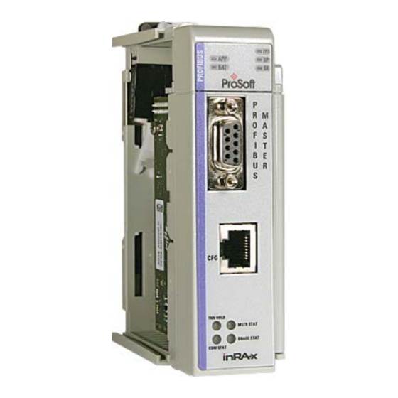
ProSoft Technology inRax MVI69-PDPMV1 Manuals
Manuals and User Guides for ProSoft Technology inRax MVI69-PDPMV1. We have
1
ProSoft Technology inRax MVI69-PDPMV1 manual available for free PDF download: User Manual
ProSoft Technology inRax MVI69-PDPMV1 User Manual (225 pages)
Brand:
ProSoft Technology
| Category:
Network Hardware
| Size: 2 MB
Table of Contents
Your Feedback Please
2
How to Contact Us
2
Prosoft Technology Product Documentation
2
Important Installation Instructions
3
MVI (Multi Vendor Interface) Modules
3
Warnings
3
Battery Life Advisory
4
Markings
4
Table of Contents
5
Guide to the MVI69-PDPMV1 User Manual
9
1 Start here
11
System Requirements
12
Package Contents
13
Installing Prosoft Configuration Builder Software
14
Setting Jumpers
15
Installing the Module
16
2 Ladder Logic
19
MVI69-PDPMV1 Sample Add-On Instruction Import Procedure
20
Creating a New Rslogix5000 Project
21
Creating the Module
21
Importing the Ladder Rung
24
Adding Multiple Modules (Optional)
28
Connecting Your PC to the Processor
35
Downloading the Sample Program to the Processor
36
Adding the Module to an Existing Compactlogix Project
39
Adding the Module to an Existing Micrologix Project
43
3 Module Setup
45
Connecting Your PC to the Module
46
Configuring the Module
47
Setting up the Project
47
Setting Module Parameters
49
Configuring the PROFIBUS Master
51
Installing the GSD Files
53
Configuring the PROFIBUS Slaves
53
Calculating the Checksums
66
Printing the Processor Network Memory Map
66
Backing up the Project
68
Downloading the Project to the Module Using a Serial COM Port
70
Disabling the Rslinx Driver for the Com Port on the PC
71
Downloading the Project to the Module Using Cipconnect
73
Example
75
4 Mailbox Messaging
81
Mailbox Message Queuing
82
Queue Timeouts
82
Sending a Mailbox Message in Rslogix 5000
83
Receiving Mailbox Message Responses from the Module
84
Special Function Mailbox Messaging Commands
85
Mailbox Message: Set Operating Mode
88
Mailbox Message: Set Slave Mode
90
Mailbox Message: Get Slave Diagnostics
94
Mailbox Message: Get Slave Configuration
96
Mailbox Message: Set Slave Address
98
Mailbox Message: Get Live List
100
Mailbox Message: Start Slave
102
Mailbox Message: Stop Slave
104
Mailbox Message: Class 1 Acyclic Data Read
106
Mailbox Message: Class 1 Acyclic Data Write
108
Mailbox Message: Initiate Class 2 Connection
110
Mailbox Message: Class 2 Acyclic Data Read
116
Mailbox Message: Class 2 Acyclic Data Write
118
Mailbox Message: Abort Class 2 Connection
120
Mailbox Message: Class 2 Connection Abort Indication
122
Mailbox Message: Alarm Indication
126
Mailbox Messaging Error Codes
128
Acyclic Message Status Word
128
Return Codes
129
Error Codes
130
DPV1 Class 1-Related Error Codes
131
DPV1 Class 2-Related Error Codes
132
5 Diagnostics and Troubleshooting
133
Verifying Correct Operation
134
Checking the PROFIBUS Leds on the MVI69-PDPMV1
134
Viewing the Online Status of the PROFIBUS Network
135
Viewing the Controller Tags in Rslogix 5000
141
Basic Troubleshooting Steps
143
LED Indicators: Front of MVI69 Module
144
Module Status Indicators
144
PROFIBUS Master Indicators
145
Using Prosoft Configuration Builder (PCB) for Diagnostics
147
Using the Diagnostic Window in Prosoft Configuration Builder
147
Navigation
150
Main Menu
151
Reading Status Data from the Module
154
Standard PROFIBUS Slave Diagnostic Bytes
155
Byte 0 - Station Status 1 Bits
155
Byte 1 - Station Status 2 Bits
155
Byte 2 - Station Status 3 Bits
156
Byte 3 - Master Address
156
Byte 4 - Ident Number High
156
Byte 5 - Ident Number Low
156
6 Reference
157
Product Specifications
157
General Specifications
158
Hardware Specifications
158
Functional Specifications
159
PROFIBUS DP Architecture
160
Bus Access
161
Token Passing
161
Master/Slave Communication Phases
161
Communication Types
161
Master/Slave Polling
162
Functional Overview
163
About the PROFIBUS Protocol
163
General Overview
163
Block Numbers for Transfer
165
MVI69 Input and Output Data Blocks
167
PROFIBUS Comdtm
184
Prosoft Technology Product Availability
185
Introduction to PROFIBUS Comdtm
185
Installation
189
Quick Start
190
Verifying the Comdtm Version and Comdtm Install Version
199
Configuration/Debug Port
205
DB9 to RJ45 Adaptor (Cable 14)
205
PROFIBUS Master Port
206
Supported PROFIBUS Services
207
Constructing a Bus Cable for PROFIBUS DP
208
7 Support, Service & Warranty
213
Contacting Technical Support
213
Return Material Authorization (RMA) Policies and Conditions
215
Returning any Product
215
Returning Units under Warranty
216
Returning Units out of Warranty
216
Limited Warranty
217
What Is Covered by this Warranty
217
What Is Not Covered by this Warranty
218
Disclaimer Regarding High Risk Activities
218
Intellectual Property Indemnity
219
Disclaimer of All Other Warranties
219
Limitation of Remedies
220
Time Limit for Bringing Suit
220
No Other Warranties
220
Allocation of Risks
220
Controlling Law and Severability
221
Index
223
Prosoft Technology, Inc
225
Advertisement
Advertisement
Related Products
ProSoft Technology inRAx MVI56-PDPMV1
ProSoft Technology inRAx MVI-ADMNET
ProSoft Technology MVI69E-MBTCP
ProSoft Technology inRax MVI69-101M
ProSoft Technology MVI69E-GEC
ProSoft Technology MVI69-GSC CompactLogix
ProSoft Technology MVI69-GSC MicroLogix
ProSoft Technology MVI69E-LDM-MQTT
ProSoft Technology MVI69-GEC
ProSoft Technology inRAX MVI69-S3964R
ProSoft Technology Categories
Control Unit
Gateway
Wireless Router
Network Hardware
I/O Systems
More ProSoft Technology Manuals
Login
Sign In
OR
Sign in with Facebook
Sign in with Google
Upload manual
Upload from disk
Upload from URL