Table of Contents
Advertisement
Quick Links
Advertisement
Table of Contents

Subscribe to Our Youtube Channel
Related Manuals for ProSoft Technology ProLinx PDPM


Summary of Contents for ProSoft Technology ProLinx PDPM
- Page 1 PDPM ProLinx Gateway PROFIBUS DP Master June 24, 2013 PROTOCOL MANUAL...
-
Page 2: Your Feedback Please
In an effort to conserve paper, ProSoft Technology no longer includes printed manuals with our product shipments. User Manuals, Datasheets, Sample Ladder Files, and Configuration Files are provided on the enclosed DVD and are available at no charge from our web site: http://www.prosoft-technology.com... -
Page 3: Prolinx Gateways With Ethernet Ports
32K maximum HTML page size (previously limited to 16K) 1.1.1 To upgrade a previously purchased Series C model Contact your ProSoft Technology distributor to order the upgrade and obtain a Returned Merchandise Authorization (RMA) to return the unit to ProSoft Technology. -
Page 5: Table Of Contents
3.1.15 Online Functions ..................... 33 PDPM Protocol Configuration [PROFIBUS Master] ....................43 4.1.1 Swap Input Bytes ....................44 4.1.2 Swap Output Bytes ....................44 4.1.3 Comm Failure Mode ....................44 ProSoft Technology, Inc. Page 5 of 70 June 24, 2013... - Page 6 PROFIBUS Master Port ..................60 Supported PROFIBUS Services ................60 Constructing a Bus Cable for PROFIBUS DP ............61 Support, Service & Warranty Contacting Technical Support ......................67 Warranty Information ....................68 Index Page 6 of 70 ProSoft Technology, Inc. June 24, 2013...
-
Page 7: Functional Overview
I/O systems, motor control centers, and variable speed drives. PROFIBUS DP Architecture The PROFIBUS DP Master network supports multiple Master systems with several slaves. The following table shows the most important features of PROFIBUS DP Master: ProSoft Technology, Inc. Page 7 of 70 June 24, 2013... -
Page 8: Bus Access
Broadcast communication: An active node sends an unacknowledged message to all other nodes (Master and slaves) Multicast communication (control instructions): An active node sends an unacknowledged message to a group of nodes (Master and slaves) Page 8 of 70 ProSoft Technology, Inc. June 24, 2013... -
Page 9: Master/Slave Communication Phases
ProLinx Communication Gateways Internal Database Register range Input Image Data Output Image Other PROFIBUS Data ProLinx Master Protocol Driver Driver PROFIBUS Master Status & User Data 3999 ProSoft Technology, Inc. Page 9 of 70 June 24, 2013... -
Page 10: Profibus Master Port Specifications
A write command issued to a slave device by the master driver uses the data in the internal database to write to the slave device. Page 10 of 70 ProSoft Technology, Inc. June 24, 2013... -
Page 11: Master/Slave Communication Phases
Port Physical and Protocol Specifications The ProLinx module supports the PROFIBUS Master protocol as a Master on either a Mono-Master or Multi-Master network. Profibus Master Config Debug Port 0 Port 0 ACTIVE ACTIVE ACTIVE ProSoft Technology, Inc. Page 11 of 70 June 24, 2013... -
Page 12: Serial Port Specifications
ProLinx modules with 4 serial ports have a separate serial interface board for serial Ports 1, 2, and 3. These serial ports are buffered and can handle communications up to 115,200 baud. Page 12 of 70 ProSoft Technology, Inc. June 24, 2013... -
Page 13: Configuration
DVD. As the setup program runs, the program prompts you to make selections as to what components to install. Select the appropriate components based on the following example. ProSoft Technology, Inc. Page 13 of 70 June 24, 2013... - Page 14 Note: ProLinx SyCon does not use the OPC server and a license number must be entered in order to complete the installation. Enter the license code and company information when prompted. You will find the license code in E:\ProLinx\Utilities\Sycon\SyCon\LIC_044.TXT (double-click the filename to open in Notepad.exe) Page 14 of 70 ProSoft Technology, Inc. June 24, 2013...
- Page 15 You will be prompted to import the BMP files that accompany the GSD files. Click Open to import each of the selected BMP files. Other Devices For other devices, these files should be provided and updated by the device manufacturer. ProSoft Technology, Inc. Page 15 of 70 June 24, 2013...
-
Page 16: Configuring A Profibus Using Prolinx Sycon
Perform the following procedure to configure the PROFIBUS system. Select File - New from the menu. ProLinx SyCon will start the configuration mode and open the window with the bus line. Page 16 of 70 ProSoft Technology, Inc. June 24, 2013... -
Page 17: Inserting A Master
If you chose the ProLinx PROFIBUS Master, the Vendor information is displayed exactly as shown in the following example: In this example, a PROFIBUS-DP Master will be added with Station Address 1 and the Description Master 1. ProSoft Technology, Inc. Page 17 of 70 June 24, 2013... -
Page 18: Master Configuration
Activate or deactivate the auto addressing 3.1.6 Inserting a Slave Device To insert new PROFIBUS-DP slaves in the configuration, select the Insert - Slave menu to open the selection window or click the following button: Page 18 of 70 ProSoft Technology, Inc. June 24, 2013... - Page 19 These addresses correspond to the application in the PLC. Select the menu Settings - DP Slave Configuration or double-click on a slave to open Slave Configuration dialog box. ProSoft Technology, Inc. Page 19 of 70 June 24, 2013...
- Page 20 If not already present, select all modules from the upper table and insert them in the lower table to be configurable. The sequence of the modules in the lower list is important and must correspond to the real physical slave configuration. Page 20 of 70 ProSoft Technology, Inc. June 24, 2013...
- Page 21 ProSoft PROFIBUS Slave (PDPS) devices have a configurable parameter for SPC3 User Prm Byte. The following illustration shows the value of this parameter in Sycon, the configuration tool for ProLinx PROFIBUS Master devices. ProSoft Technology, Inc. Page 21 of 70 June 24, 2013...
- Page 22 DXB-publisher-functionality of Publisher_Enable = 0, DXB- request-telegrams are ignored; the SPC3 is activated with this Publisher_Enable = 1, DXB- request-telegramme are processed 6 to 7 To be parameterized with 0 Page 22 of 70 ProSoft Technology, Inc. June 24, 2013...
-
Page 23: Settings
If there is a Master device connected, the firmware is displayed otherwise there will be a timeout error. Bus Parameter For a PROFIBUS DP system with one master, the only parameter that must be selected is the baud rate. ProSoft Technology, Inc. Page 23 of 70 June 24, 2013... - Page 24 1000 ms Addressing mode: Word addresses Storage formats: Big Endian Parameter Data User parameter data may be edited in the Parameter Data window by choosing Settings - Parameter Data. Page 24 of 70 ProSoft Technology, Inc. June 24, 2013...
- Page 25 Hex: All parameters of the slave are shown in hexadecimal representation Common: Parameter data of the head station Module: Parameter data of the separate modules ProSoft Technology, Inc. Page 25 of 70 June 24, 2013...
- Page 26 It is possible to change back into the hexadecimal description by selecting the Hex button. With a double click on one row of the parameter data, you are able to change the value using the following dialog box. Page 26 of 70 ProSoft Technology, Inc. June 24, 2013...
- Page 27 Choose Settings, then Group Membership from the menu. Select which group should support the DP-Freeze and DP-Sync command. The Group Assignment button allows you to assign slaves to with the desired characteristics. ProSoft Technology, Inc. Page 27 of 70 June 24, 2013...
-
Page 28: Project Information
Common information regarding the project can be written to the configuration documentation by choosing Settings, then Project Information from the menu. This information can be printed or displayed in the window. Page 28 of 70 ProSoft Technology, Inc. June 24, 2013... -
Page 29: Path
Select the desired language, and confirm the entry with the OK button. A comment appears, and prompts you to restart the application to make the changes effective. After restart, PROLINX SyCon will be uses the selected language. ProSoft Technology, Inc. Page 29 of 70 June 24, 2013... -
Page 30: View The Configuration
Choose View, then Address Table to display the list of addresses. Select the master as actual master to display the address table. You can sort the addresses by station addresses or by data addresses. Page 30 of 70 ProSoft Technology, Inc. June 24, 2013... - Page 31 The Auto Addressing mode must be inactive in order to change address assignments. Click on a cross and hold down the left mouse button. The pointer changes to an arrow. ProSoft Technology, Inc. Page 31 of 70 June 24, 2013...
-
Page 32: Printing The Configuration File
The configuration is transmitted to the selected device and stored into FLASH memory statically. This enables it to be available after the power is switched off and on in the device. Page 32 of 70 ProSoft Technology, Inc. June 24, 2013... -
Page 33: Online Functions
PROLINX SyCon also displays the letters Diag if the device signals diagnostic information. This information is displayed closer if you click with the mouse onto the corresponding device in debug mode. ProSoft Technology, Inc. Page 33 of 70 June 24, 2013... - Page 34 If diagnostic information is available for a specific device, the text Diag appears next to the device icon in red. To access additional device-specific diagnostic information, double-click on the device itself, or select the device, then select Online - Device Diagnostic. Page 34 of 70 ProSoft Technology, Inc. June 24, 2013...
- Page 35 GSD-File. Use the View/Device Table menu to view this information. If parameter data is configured in PROLINX SyCon, but the slave does not support it, reduce the parameter data in PROLINX SyCon to a length of zero. Invalid_Slave_Response ProSoft Technology, Inc. Page 35 of 70 June 24, 2013...
- Page 36 The meaning "Not_Ready" can be seen as not ready to perform the I/O data exchange. This may indicate several slave specific reasons. Usually the bit is set in combination with one of the other fault bits. Station_Non_Existent Page 36 of 70 ProSoft Technology, Inc. June 24, 2013...
- Page 37 PROFIBUS user organization. This identification code can serve in PROLINX SyCon to compare it with the Ident code of the GSD file of the configured slave if a parameterization error is reported. ProSoft Technology, Inc. Page 37 of 70 June 24, 2013...
- Page 38 This menu activates a list of available structures. The listed structures can be displayed to show the values. Several task states are available. Note: All items in this list do not work for this master. Page 38 of 70 ProSoft Technology, Inc. June 24, 2013...
- Page 39 The number of detected timeouts is fixed in the statistic bus information variable. The bit will be set when the first timeout was detected and will not be deleted. ProSoft Technology, Inc. Page 39 of 70 June 24, 2013...
- Page 40 The status of the live list is not automatically updated online. Click on the Update button after you change your inputs to update this window. Page 40 of 70 ProSoft Technology, Inc. June 24, 2013...
- Page 41 This is a simple tool used to display and enter only the first 32 bytes of the process image. Note: The I/O monitor cannot be used with the ProLinx PROFIBUS Master unit. ProSoft Technology, Inc. Page 41 of 70 June 24, 2013...
- Page 42 Manually start or stop the communication between masters and slaves by selecting menu Online - Start Communication and Stop Communication respectively. Device Info Select the menu Online - Device Info to see information about the selected hardware in the configuration. Page 42 of 70 ProSoft Technology, Inc. June 24, 2013...
-
Page 43: Pdpm Protocol Configuration
No #Swap bytes in output image (yes or no) Comm Failure Mode 1 #0=x-fer on comm fail, 1=no x-fer on fail Watchdog Register 1000 #DB register to monitor for change ProSoft Technology, Inc. Page 43 of 70 June 24, 2013... -
Page 44: Swap Input Bytes
PROFIBUS output registers to a specific value (configured through the Watchdog Reset Value parameter). In order to disable this functionality set the Watchdog Register to -1. Page 44 of 70 ProSoft Technology, Inc. June 24, 2013... -
Page 45: Profibus Master Commands]
Register Count field. 4.2.2 70 - Global Cmd Execute global command using the value at the specified Database Address to the Node Address. The Data Length field specifies the Group Select parameter. ProSoft Technology, Inc. Page 45 of 70 June 24, 2013... -
Page 46: 254 - Read Cntrs
Definition No function Function will be activated (that is, Freeze input data) Function will be inactivated (that is, Unfreeze input data) Function will be inactivated (that is, Unfreeze input data) Page 46 of 70 ProSoft Technology, Inc. June 24, 2013... -
Page 47: Diagnostics And Troubleshooting
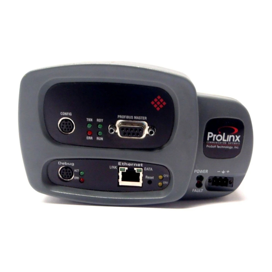
PROFIBUS Master Port status LEDs. Information on the module’s other LEDs can be found in the ProLinx Reference Guide. 5.1.1 LEDs for the PROFIBUS Master Port Color Description TKN - Token Green On PROFIBUS Master owns token. ProSoft Technology, Inc. Page 47 of 70 June 24, 2013... -
Page 48: Profibus Master Error And Status Data
The data area is initialized with zeros whenever the module is initialized. This occurs during a cold-start (power-on), reset (reset push-button pressed) or a warm-boot operation (commanded or loading of new configuration). The format of this data area is displayed below: Page 48 of 70 ProSoft Technology, Inc. June 24, 2013... -
Page 49: General Status
Byte Description Station status 1 Station status 2 Station status 3 Master address Ident number high Ident number low 5.3.4 Byte 0 - Station Status 1 Bits ProSoft Technology, Inc. Page 49 of 70 June 24, 2013... -
Page 50: Byte 1 - Station Status 2 Bits
Slave device Watchdog on Freeze mode Sync mode Reserved Slave deactivated 5.3.6 Byte 2 - Station Status 3 Bits Description Reserved Reserved Reserved Reserved Reserved Reserved Reserved Extended diagnostic overflow Page 50 of 70 ProSoft Technology, Inc. June 24, 2013... -
Page 51: Byte 3 - Master Address
DRIVER: No COM handle found DRIVER: COM port already opened DRIVER: Function call into driver failed DRIVER: Internal driver error DRIVER: Could not create read thread DRIVER: Could not create read event ProSoft Technology, Inc. Page 51 of 70 June 24, 2013... -
Page 52: Rcs Error Numbers (4 To 93)
Command messages and answer messages communicate between the application (for example, the system configuration) and the master device. An example of this communication is the download of a configuration. Page 52 of 70 ProSoft Technology, Inc. June 24, 2013... - Page 53 FLASH timeout error Access protection error while deleting the FLASH FLASH size does not match or not enough FLASH memory Wrong structure type Wrong length of structure Structure does not exist ProSoft Technology, Inc. Page 53 of 70 June 24, 2013...
-
Page 54: Data Server Error Numbers (1001
User function invalid 2005 User function pointer invalid 2006 User data invalid 5.4.5 Converting Functions Error Numbers (4000 … 4098) The following table lists the error numbers of the converting functions. Page 54 of 70 ProSoft Technology, Inc. June 24, 2013... - Page 55 SegLen in structure FILE_INFO_T is smaller then the length in the file. Return of function dbm_restore_data 4053 The header file holds an other information for a length than in the segment itself 4054 Not enough memory for allocation on the PC ProSoft Technology, Inc. Page 55 of 70 June 24, 2013...
- Page 56 No data in a ODBC table 4088 No entry 4089 ODBC set length not valid 4090 Not enough data sets in ODBC table 4091 Table CreateTab not found 4092 Error in structure of table CreateTab Page 56 of 70 ProSoft Technology, Inc. June 24, 2013...
-
Page 57: Data Base Functions Error Numbers (5001
Function LongToShort: Not enough space in pvD 5006 Function PackStringDumpToByteArray: Not enough space in pvD 5007 Function PackStringBumpToByteArray: A character was found, which does not match a HEX value 5008 Function PackStringDumpToByteArray: Number of character odd ProSoft Technology, Inc. Page 57 of 70 June 24, 2013... - Page 58 PDPM ♦ ProLinx Gateway Protocol Manual PROFIBUS DP Master Page 58 of 70 ProSoft Technology, Inc. June 24, 2013...
-
Page 59: Reference
DB9M adapter cable is included with the module. This port permits a PC-based terminal emulation program to view configuration and status data in the module and to control the module. Here are the cable pinouts for RS-232 communication on this port. ProSoft Technology, Inc. Page 59 of 70 June 24, 2013... -
Page 60: Db9 To Mini-Din Adaptor (Cable 09)
The following diagram has been imported from the PROFIBUS Master documentation. Note that the signals to reference are the D-Sub signals in the table. Supported PROFIBUS Services The following table lists all available services according to the PROFIBUS specification. Page 60 of 70 ProSoft Technology, Inc. June 24, 2013... -
Page 61: Constructing A Bus Cable For Profibus Dp
PROFIBUS cable: Belden part number 3079A. To construct the cable, proceed as follows: Cut the cable to the required length. Prepare the cable ends as shown in the illustration (dimensions in mm): ProSoft Technology, Inc. Page 61 of 70 June 24, 2013... - Page 62 Green leads in terminal A Red lead in terminal B Note: Do not tighten the corresponding screws yet. Connection terminal assignment on the PROFIBUS DP: A Incoming cable B Outgoing cable Page 62 of 70 ProSoft Technology, Inc. June 24, 2013...
- Page 63 The PROFIBUS connector with termination is required at the beginning and the end of the bus. These connectors emulate the line impedance. It is recommended that at least one connector with diagnostics interface is used. ProSoft Technology, Inc. Page 63 of 70 June 24, 2013...
- Page 64 To prevent this, it is imperative that there is potential equalization between all the attached installation components and devices. This example indicates the system components and devices in a system with equipotential bonding. Page 64 of 70 ProSoft Technology, Inc. June 24, 2013...
- Page 65 If this is not possible because of system or construction specific reasons however, use distributed ground with a capacitive coupling of high frequency interference signals. This representation shows distributed grounding with capacitive coupling. ProSoft Technology, Inc. Page 65 of 70 June 24, 2013...
- Page 66 PDPM ♦ ProLinx Gateway Protocol Manual PROFIBUS DP Master Page 66 of 70 ProSoft Technology, Inc. June 24, 2013...
-
Page 67: Support, Service & Warranty
Contacting Technical Support ............... 67 Warranty Information ................68 Contacting Technical Support ProSoft Technology, Inc. (ProSoft) is committed to providing the most efficient and effective support possible. Before calling, please gather the following information to assist in expediting this process: Product Version Number... -
Page 68: Warranty Information
E-mail: brasil@prosoft-technology.com Languages spoken include: Portuguese, English Warranty Information For complete details regarding ProSoft Technology’s TERMS & CONDITIONS OF SALE, WARRANTY, SUPPORT, SERVICE AND RETURN MATERIAL AUTHORIZATION INSTRUCTIONS please see the documents on the Product DVD or go to www.prosoft-technology/warranty... -
Page 69: Index
Data Base Functions Error Numbers (5001 … 5008) • Pinouts • 2, 60, 61 Port Physical and Protocol Specifications • 11 Data Server Error Numbers (1001 … 1009) • 54 ProSoft Technology, Inc. Page 69 of 70 June 24, 2013... - Page 70 View Device Table • 30 View the Configuration • 30 Viewing Error and Status Data • 48 Warranty Information • 68 Watchdog Parameters • 44 Your Feedback Please • 2 Page 70 of 70 ProSoft Technology, Inc. June 24, 2013...
Need help?
Do you have a question about the ProLinx PDPM and is the answer not in the manual?
Questions and answers