Table of Contents
Advertisement
Quick Links
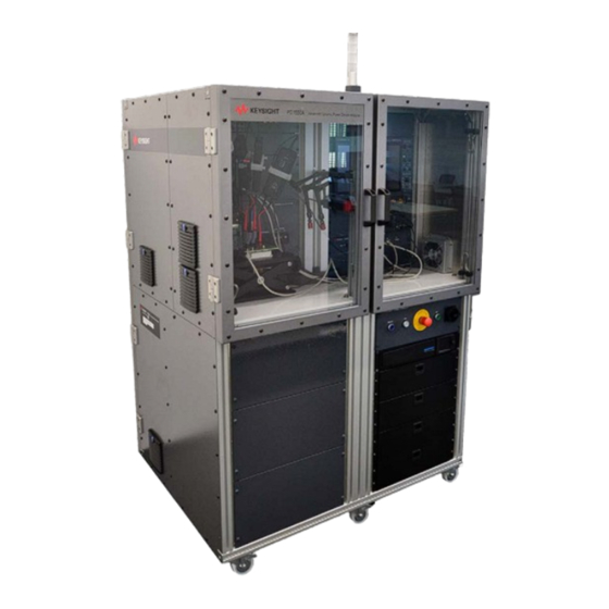
PD1550A Advanced Dynamic Power
Device Analyzer
System Installation Guide
Provides detailed information to install the Double-Pulse Test Rack and Safety Enclosure for power modules at a customer
site. The Rack and Safety Enclosure is used with the PD1550A Dynamic Power Device Analyzer/Double-Pulse Tester.
INSTALLATION GUIDE
Advertisement
Chapters
Table of Contents

Related Manuals for Keysight PD1550A


Summary of Contents for Keysight PD1550A
- Page 1 Device Analyzer System Installation Guide Provides detailed information to install the Double-Pulse Test Rack and Safety Enclosure for power modules at a customer site. The Rack and Safety Enclosure is used with the PD1550A Dynamic Power Device Analyzer/Double-Pulse Tester. INSTALLATION GUIDE...
- Page 2 Warranty © Keysight Technologies, Inc. 2023 No part of this manual may be repro- To contact Keysight for sales and techni- THE MATERIAL CONTAINED IN THIS duced in any form or by any means cal support, refer to the support links on DOCUMENT IS PROVIDED “AS IS,”...
- Page 3 Failure to comply with these precautions or with specific warnings elsewhere in this manual may impair the protections provided by the system. In addition, it violates safety standards of design, manufacture, and intended use of the system. Keysight assumes no liability for customer’s failure to comply with these requirements.
- Page 4 • Instruments, probes or cables that appear damaged or defective should be made inoperative and secured against unintended operation until they can be repaired by qualified service personnel. Return the product to a Keysight sales or service office for service and repair to ensure that safety features are maintained.
- Page 5 Return the product to a precautions or with specific warnings containers of such liquids. Keysight Sales and Service Office to or operating instructions in the product ensure that safety features are main- manuals violates safety standards of Cleaning tained.
- Page 6 Safety and Regulatory Symbols A CAUTION denotes a hazard. It calls attention to an operating pro- cedure or practice that, if not cor- The CE marking is a registered trade- rectly performed or adhered to, R-R-Kst-SP21786 mark of the European Community (if could result in damage to the accompanied by a year, it is the year South Korean Certification (KC) mark.
- Page 7 Si prega di fare riferimento al sito key- Japanese sight.com/go/takeback per compren- dere le opzioni di Commercializzazione 車輪付きゴミ箱に×マークは、EU DIRECTIVEやその他の国の法律で義 con Keysight oltre alle istruzioni per il ritiro del prodotto. 務付けられている廃電気・電子機器 (WEEE)の分別回収が必要であるこ とを示しています。 Spanish keysight.com/go/takeback では、製 品のテイクバック方法に加えて、 El símbolo del contenedor de basura Keysight の下取りオプションに...
-
Page 8: Table Of Contents
PD1550A Documentation ........ - Page 9 Keysight Isolated Probe Unit........
- Page 10 DP0031A Settings in the Oscilloscope User Interface....105 PD1550A System Calibration (AutoCal) ......106 Requirements .
- Page 11 PD1550A High Voltage Wiring ........
- Page 12 High-Side Drain/Collector Current ......142 E Index Keysight Double Pulse Test Rack and Safety Enclosure Instalation Guide xiii...
- Page 13 Keysight Double Pulse Test Rack and Safety Enclosure Instalation Guide...
- Page 14 See “Customer Responsibilities” on page 16. This System Installation Guide provides step-by-step instructions to install the PD1550A Dynamic Power Device Analyzer/Double-Pulse Tester and connect accessories. Note that the PD1550A is part of the overall PD1000A Power Device Measurement System for Advanced Modeling. In this chapter:...
-
Page 15: Site Preparation
Receive the PD1550A Double-Pulse Test System. Uncrating — You should remove the PD1550A system the shipping crate. You may inventory the shipment using the enclosed packing list. See Chapter 2. Site Preparation and Maintenance — Ensure the operating environment (space, noise, etc.) is suitable. -
Page 16: Static-Safe Handling Procedures
To ensure user safety, the static-safe accessories must provide at least 1 M of isolation from ground. Some of the material in the safety enclosure can generate static electricity. Take care if you are using ESD sensitive devices in its vicinity. Keysight PD1550A Installation Guide... -
Page 17: Power Module Test Rack And Safety Enclosure Location
Shelf: 55 cm (21 5/8”)Wide 51.5 cm (20 1/4”) Deep 77.5 cm (30.5”) from floor 1.27 M (50”) Includes hinges and side shelf 1.1 M (42”) folded against rack includes front and rear door handles Keysight PD1550A Installation Guide... -
Page 18: Rack Ventilation
Top of Rack Left Side of Rack Right Side of Rack Rear of Rack Figure 1 Air Flow through the DPT Rack and Safety Enclosure (Blue arrows are fresh air in / Red arrows are hot air exhaust) Keysight PD1550A Installation Guide... -
Page 19: Connect The Rack And Safety Enclosure To Ac Mains
AC Power Cord A country-specific mains power cord (2.5 m [98 inches] long, 3 conductor, IEC-60320 C19 socket on one end) is available with the PD1550A Rack and Safety Enclosure. LEAKAGE CURRENT! Due to the types of instruments installed in this cabinet, there is a risk of leakage current (>... -
Page 20: Connection Of The Pd1550A To The Ac Mains
Connection of the PD1550A to the AC Mains Site Preparation Connection of the PD1550A to the AC Mains AC wiring and the Mains Disconnect are subject to local and regional electrical codes. A licensed electrician must determine and install the appropriate Mains Disconnect. -
Page 21: Receiving The Pd1550A
Inspect the rack and instruments for damage (scratches, dents, bent pieces, etc.). If the rack or any instrument is damaged, notify the carrier and the nearest Keysight Sales and Service office immediately. Moving the Rack and Safety Enclosure On initial receipt, the Rack and Safety Enclosure plus shipping crate exceeds 560 kg (1,290 lbs). -
Page 22: Inventory The Shipment
The DPT Rack and Safety Enclosure comes in at least two shipping containers - a wood crate for the PD1550A (all test instruments are factory installed) and one or more cardboard box for all accessories. Use the packing list that comes with your system to ensure you received all pieces of the system. - Page 23 Site Preparation Receiving the PD1550A Description and Keysight Part Number Quantity Graphic 1854-2245 62 mm IGBT Half-Bridge Test Module (Infineon FF500R17KE4 or equivalent) 1855-3111 62 mm MOSFET Half-Bridge Test Module (CREE [Wolfspeed] CAS300M17BM2 or equivalent) PD1550-61901 0.05 (50 mShunt , (PD1072A-FG for repair and Cal services) PD1550-61902 0.005 ...
- Page 24 Goes from PD1000-60002 Protection Probe to Shunt on DUT Interface Board IMPORTANT: Replace this cable only with same Keysight PN. This is required to maintain deskew in the system. PD1550-60003, Standard Lift Table 180 mm x 100 mm Keysight PD1550A Installation Guide...
- Page 25 Site Preparation Receiving the PD1550A Description and Keysight Part Number Quantity Graphic Holdit Pro-Set Probe Holders (no Keysight part number) Ferrite-core Inductor (9170-1792) One core for the N2873A Oscilloscope Probe. The remaining three are not used. PD1550-00010 Sheet of 14 probe labels for...
-
Page 26: Pd1550A Accessories (Not Included)
Receiving the PD1550A Site Preparation PD1550A Accessories (not included) The following accessories are used in the PD1550A but you must specify the quantity in the product order. Description and Keysight Part Number Quantity Graphic PD1550-66561 DPT Interface Board for 62 mm DUT modules with decoupling capacitors. -
Page 27: Optional (Not Required) Pd1550A Accessories
Site Preparation Receiving the PD1550A Optional (not required) PD1550A Accessories The following accessories are used in the PD1550A but not required. Description and Part Number Quantity Graphic PD1550-60004 (Opt. LT2) Heavy Duty Lift Table 300 mm x 150 mm (for larger DUT modules) -
Page 28: What Is Not Supplied With The Rack And Safety Enclosure
What is Not Supplied with the Rack and Safety Enclosure Site Preparation The following cables are included with the PD1550A and are used only for the AutoCalibration procedure: Description Quantity Graphic Black Test Patch Lead, 0.64 mm Square Pin Socket to 4 mm... -
Page 29: Pd1550A Documentation
All necessary power cords and cables are included in the DPT system Rack and Safety Enclosure. - PD1550A Control Software Guide: Provides detailed information to install, configure, and use the PD1000A Control Software for the PD1550A DPT system. PN: PD1550-90001 - PD1550A Operation and General Maintenance Guide: Provides detailed information to operate and maintain the PD1550A Test Rack and Safety Enclosure. -
Page 30: Simplified System Diagrams
Refer to “Simplified System Wiring Diagrams” on page 133 for diagrams. These diagrams illustrate the overall system wiring. The test instruments, Power Distribution Unit, instrument power cords, LAN cables, and all of the Safety Electronics are pre-installed in the PD1550A Rack and Safety Enclosure for your convenience. Keysight PD1550A Installation Guide... - Page 31 Site Preparation Simplified System Diagrams Keysight PD1550A Installation Guide...
-
Page 32: Uncrate The Pd1550A Rack And Safety Enclosure
PD1550A Double-Pulse Test Rack and Safety Enclosure Installation Guide Uncrate the PD1550A Rack and Safety Enclosure The Double-Pulse Test (DPT) Rack and Safety Enclosure is the largest of the two shipping container shipped for the system. This chapter describes how to uncrate the DPT Rack and Safety Enclosure. -
Page 33: Uncrate The Rack And Safety Enclosure
Uncrate the Rack and Safety Enclosure Uncrate the Rack and Safety Enclosure Use the following procedure to remove the rack from the shipping crate. Keysight recommends using two people to uncrate the Rack and Safety Enclosure. Wear work gloves to protect against splinters. - Page 34 Uncrate the Rack and Safety Enclosure Uncrate the PD1550A Rack and Safety Enclosure 2 Remove the TORX T40 screws and four clamps securing the ramp to the sides of the shipping crate. Ramp side of crate (shown with clamps and...
- Page 35 Uncrate the PD1550A Rack and Safety Enclosure Uncrate the Rack and Safety Enclosure 3 Carefully unfold the ramp down to the floor. Figure 4 Carefully open the ramp 4 Remove the top braces from inside the shipping crate. Top braces...
- Page 36 Uncrate the Rack and Safety Enclosure Uncrate the PD1550A Rack and Safety Enclosure Although it is possible to remove the PD1550A Rack and Safety Enclosure from the shipping crate without removing the sides and back of the crate, Keysight recommends removing crate from the pallet.
- Page 37 Uncrate the PD1550A Rack and Safety Enclosure Uncrate the Rack and Safety Enclosure 6 Carefully slide the crate body (sides, back and top) of the shipping crate away from the shipping pallet. Set crate body on the floor behind the pallet.
- Page 38 Uncrate the Rack and Safety Enclosure Uncrate the PD1550A Rack and Safety Enclosure 7 Remove the front, side and rear braces from the pallet. Braces Figure 8 Remove the Braces from the Pallet (Rack packing materials not shown) 8 Remove packing materials from the Rack and Safety Enclosure.
- Page 39 At least two people are required to roll the Rack and Safety Enclosure down the ramp and to its final location. Keysight recommends, if possible, that you save the shipping crate and pallet if you plan to ship the rack to a different location.
-
Page 40: Moving The Rack And Safety Enclosure
Moving the Rack and Safety Enclosure Uncrate the PD1550A Rack and Safety Enclosure Moving the Rack and Safety Enclosure The Rack and Safety Enclosure has six wheels on the bottom of the rack. Be careful, the rack’s center of gravity is high. The rack might tilt over when moving. -
Page 41: Re-Crating The Rack And Safety Enclosure For Shipping
Re-crating the Rack and Safety Enclosure for Shipping If you need to ship the Double-Pulse Test system to a different location – beyond where it can be rolled on its casters – prepare the PD1550A system for shipping per the following instructions. -
Page 42: Accessory And Probe Installation
PD1550A Double-Pulse Test Rack and Safety Enclosure Installation Guide Accessory and Probe Installation This chapter describes the PD1550A system installation process. It includes both system rack hardware assembly as well as installation requirements for general system operation. Tools Required to Install Accessories... -
Page 43: Tools Required To Install Accessories
“Apply Power and Turn On the PD1500A” on page 47 for information regarding system turn on. Stabilize the Rack After moving the PD1550A rack to its final position, lock the casters to prevent accidental moving. Press down to lock caster... -
Page 44: Install Tower Light On Top Of The Rack
1 Locate the tower light in the group of accessories. 2 Standing on a small step ladder, locate and remove two Phillips mounting screws on top of the rack. 3 Connect the 8-pin Tower Light cable and securely tighten. Keysight PD1550A Installation Guide... - Page 45 - Yellow indicates a system failure or the system is turning on. - Green indicates no high voltage is present, the front doors may be opened. - Blue indicates a test is running, the front doors are locked. Keysight PD1550A Installation Guide...
-
Page 46: Apply Power And Turn On The Pd1500A
Press and hold the Door Open button to open the two front doors.-- you may need to pull very hard to open the doors. Remember, to open the doors on the PD1550A: – Power must be supplied to the PD1550A system – PD1550A system turned on –... -
Page 47: Connect Three Short Bnc Cables
Three short BNC-BNC cables should come pre-installed from the factory. These BNC - BNC cables connect the Waveform Generator to the patch panel immediately below the oscilloscope. Ensure that these cables are in place. Figure 10 Three short BNC - BNC cables Keysight PD1550A Installation Guide... -
Page 48: Rack Connections
Rack Connections USB, External LAN, and HDMI Connectors The following sockets are on the right side of the PD1550A rack. Connect your site LAN cable or a LAN cable to the controller PC to the LAN External socket. The two USB and the HDMI sockets are reserved for future use only. Do not connect anything to these three sockets. -
Page 49: Lan External, E-Stop Signal Light Connectors
These jacks are reserved for future use only. Power In / Power Out Connectors Maximum AC Power Input to the PD1550A is 12 A at 200 - 250VAC, 2800 Watts. The Power Out socket is to power an external monitor. It is rated at 6 A maximum. -
Page 50: Open The Side Shelf
Squeeze handles, both sides. Lift shelf until horizontal and locked in place. To close, squeeze handles, both sides, and lower shelf. Figure 15 Lift the shelf into position until it locks Keysight PD1550A Installation Guide... -
Page 51: Open The Drawers
Accessory and Probe Installation Open the Drawers Open the Drawers Press the latch down and pull the drawer out to open. Figure 16 Opening the Rack Drawers Keysight PD1550A Installation Guide... -
Page 52: Install Probe Holders
Insert and thread the long threaded arm of the Holdit Arm into the rail. Use a 10 mm wrench to tighten the arm on the rail. 1 Holdit Pro-Set HS9000 from Noga. For additional information see, www.hoditbynoga.com. Keysight PD1550A Installation Guide... - Page 53 Attachment to the Quick Release, pull back on the red Quick Release sleeve and insert the attachment. 8 Attach one Probe Holder on each probe. 1 Converter and XchangeCube pieces are not used and may be discarded. Keysight PD1550A Installation Guide...
-
Page 54: Add Ferrite Core Inductor To N2873A Probe
Do not over tighten the zip-ties and crimp the cable. Four ferrite clamps are provided with the PD1550A. Only this one is used. The remaining three clamps are extras and not used... -
Page 55: Install Components On Pd1550A Interface Module
The PD1550-61901, 0.05 , and PD1550-61902, 0.005 shunts will not fit with the PD1500A system DUT modules. The PD1000-61901, 0.01 and PD1000-61902, 0.001 shunts must not be used with the PD1550A system due to the higher currents used in the PD1550A system. Keysight PD1550A Installation Guide... -
Page 56: Attach 62 Mm Dut Module
It is not the best module for testing 62 mm DUT modules. The PD1550-66560 Interface Module with decoupling capacitors is an option to the PD1550A; it is the best choice for testing 62 mm DUT modules. Keysight PD1550A Installation Guide... - Page 57 Accessory and Probe Installation Install Components on PD1550A Interface Module Gate/Drain - Collector/Emitter Gate Drive Connectors Pins Figure 19 Typical 62 mm IGBT Module (62 mm FET module is similar) Keysight PD1550A Installation Guide...
- Page 58 Interface module and into the DUT. CAUTION: Do not over-tighten. M6 x 6 mm bolts Carefully fold the DUT module Gate onto the Interface Module Figure 20 Installing a 62 mm DUT Module on the PD1550A Interface Module Keysight PD1550A Installation Guide...
-
Page 59: Install Gate Drive Resistor Modules On The Interface Module
. It may take several test iterations to match the data sheet di/dt. PD1550A Gate Resistor Modules are labeled in the form: x, x, xxx, where the first value (typically 0) refers to the R resistor value on the module, the second value (typically 0) refers to the R resistor value on the module. -
Page 60: Schematic Of Path For Gate Resistors
= 0 = 0 = 4.7 Figure 22 PD1550A Gate Drive Resistor Modules How to Measure Gate Resistors You can use a DMM to measure the Gate Resistors directly on the resistor module or, after installing the Gate Resistor Modules on the Interface Module, you can measure the resistor values on the Interface Module itself. -
Page 61: Install Gate Drive Resistor Modules On The Interface Module
Accessory and Probe Installation Install Components on PD1550A Interface Module High-Side Gate Resistor Measurement Terminals. KS is for Kelvin Source. High-Side Gate Drive Resistor Module Low-Side Gate Drive Resistor Module Low-Side Gate Resistor Measurement Terminals. KS is for Kelvin Source. -
Page 62: Install Gate Drive Modules On The Interface Module
Install Components on PD1550A Interface Module Accessory and Probe Installation Install Gate Drive Modules on the Interface Module Remove the four screws (two for each module) from the Gate Drive Module mounting brackets. Carefully align the High-Side Gate Drive Module with the pins on the Interface Module. - Page 63 Accessory and Probe Installation Install Components on PD1550A Interface Module High-Side Gate Drive Mounting Screws Low-Side Gate Drive Mounting Screws Figure 26 Optional Low-Side and High-Side Gate Drive Module Mounting Screws Keysight PD1550A Installation Guide...
-
Page 64: Connect Interface Module To Pd1550A Test System
Install Components on PD1550A Interface Module Accessory and Probe Installation Connect Interface Module to PD1550A Test System If using the InTEST Thermal Plate, place it on the Lift Table first, then the DUT Module on top of the Thermal Plate. - Page 65 Accessory and Probe Installation Install Components on PD1550A Interface Module UDI Cable to High-Side Gate Drive Module UDI Cable to Low-Side Gate Drive Module UDI Cable to Interface ModuleModule Figure 27 Install UDI Cables on Gate Drive and Interface Modules...
-
Page 66: Connect Probes To Oscilloscope
Voltage, V Reserved for V Reserved for I GS,H GE,H DS,H CE,H from Isolated Probe Unit. measurements. See See below and PD1550A below and PD1550A Software User Guide. Software User Guide. Figure 28 PD1550A Oscilloscope Probe Connections Keysight PD1550A Installation Guide... - Page 67 2 Replace this cable with only the same Keysight part number. The length and type of this cable is assumed for correct Deskew. 3 Use the 0.56 N-m (5 lb-in) 5/16 in. SMA Break-over torque wrench (provided with the PD1550A system) to tighten the SMA cable connector to the PD1000-60002 Protection Probe.
- Page 68 Before connecting any cable to an oscilloscope input, short the center and outer conductors of the cable together to ground momentarily. Alternately, connect to a 50 termination adapter to discharge the cables. Keysight PD1550A Installation Guide...
-
Page 69: Connect Oscilloscope Probes To Dut Interface Module
Important: This section and the following photographs apply only to the standard 62 mm Interface Module supplied with the PD1550A system. Your custom Interface Module may be different and require different connections. Refer to Figure 29 below. Oscilloscope probes connect to the Test Interface Module as follows: Optional. - Page 70 Accessory and Probe Installation NOTE: twist probe cables 2 times before connecting to Test Interface Module. GS,L ED,L Probe with Adapter DS,H CE,H Probe DS,L CE,L Probe Probe with BNC Adapter Figure 30 Connect Probes to Test Interface Module Keysight PD1550A Installation Guide...
-
Page 71: Connect Probe For High-Side Dut Measurements
For High-Side Drain or Collector current, I , measurements, a current shunt is not available for the Keysight 62 mm Interface Modules. However, for your custom Interface Modules you may design a place to install a shunt or a small Rogowski coil current probe. This should be connected to Channel 7 on the PD1550A oscilloscope. -
Page 72: Keysight Isolated Probe Unit
Isolated Probe Unit Keysight Isolated Probe Unit The Link Port on the Keysight Isolated Probe Unit is not used. All green LEDs next to individual channels should be green. There is also a green power LED and a red LED that indicates a trigger has occurred. -
Page 73: Apply Oscilloscope Probe Labels
Connect Oscilloscope Probes to DUT Interface Module Apply Oscilloscope Probe Labels A sheet of adhesive probe labels was provided with your PD1550A. For ease of reference, you can apply the probe labels to the PD0001A or PD0031A oscilloscope probes, to adapters, or anywhere to mark oscilloscope probe usage. -
Page 74: Install Udi Cables
Install UDI Cables Accessory and Probe Installation Install UDI Cables Universal Double-Pulse Interface (UDI) cables connect the PD1550A-020 Control Unit to other test units in the system. From the front panel, they connect Connect from PD1550-68720 Control Unit to: – PD1550-66840 Gate Drive Modules (both Low-Side and High-Side) –... -
Page 75: Install Additional Test Fixture Accessories
You must select Inductor Selection > External under Output Current in the main User Interface and specify the inductor value in the PD100A Control Software. See the PD1550A Software Guide for detailed information. For the mating plugs, use pin connectors: –... -
Page 76: Range Of External Inductors
User Interface. How to select the Thermistor resistance value Select the value of the NTC Thermistor from the drop-down box. For early releases of the PD1000A Control Software for the PD1550A, this feature is not used. Keysight PD1550A Installation Guide... -
Page 77: Cable Requirements For The Pt1000Ntc Thermistor
Accessory and Probe Installation Install Additional Test Fixture Accessories Cable Requirements for the PT1000NTC Thermistor Keysight does not proved a cable for the PTC1000NTC Thermistor for PD1000A Control Software version . Figure 35 NTC Connector on Front of Test Fixture Fan Out 24 VDC An external fan is not available for PD1550A Initial Shipments. -
Page 78: Preparing The Thermocouple
Figure 37 Type K Thermocouple Jacks on Test Fixture Front For early release versions of the PD1000A Control Software for the PD1550A, these jacks and the device temperature are not supported. Preparing the Thermocouple The simplest method of preparing a thermocouple is to simply twist the wires together several times. -
Page 79: Recommendations For Using A Thermocouple
Install Additional Test Fixture Accessories Recommendations for using a Thermocouple - Use the shortest wire possible to minimize interference and noise. For additional Thermocouple information, refer to the Keysight Application Note titled, “Practical Temperature Measurements". Reading the temperature(s) in the PD1000A Control Software Select either Thermocouple1 or Thermocouple2 from the Settings >... -
Page 80: Install Optional Intest Temperature Controller With Heating Plate
IMPORTANT: InTEST (Sigma Solutions) Thermal Solutions are not available from Keysight and must be purchased directly from InTEST Thermal Solutions. Two pieces of equipment are required: the (Watlow) Heater Control Unit and a heating plate. Select from the list below and order directly from InTEST. The Controller and Heating plate are for heating the Device Under Test (DUT) only, it does not provide cooling. -
Page 81: Install The Intest Control Unit In The Pd1550A Rack
PD1550A-010 Test Fixture. 3 Install the Control Unit Rack Panel just below the PD1550-010 Test Fixture. 4 With the set of rack keys provided with your PD1550A system, open both back doors on the rack. 5 With the supplied power cord, connect the Control Unit to the multiple outlet power distribution unit inside the PD1550A rack. - Page 82 11 Adjust the Lift Table to support the weight of the Heating Plate, the DUT module, and the Interface module. 12 Plug in the PD1550A system and turn it on. Press the Reset button on the front of the PD1550A system. The Watlow Control Unit should turn on. See Figure 41 on page 84.
- Page 83 (at start-up, generally the ambient temperature) Temperature Setting Figure 41 Watlow Controller Turn-on Sequence Set the test temperature(s) in the PD1000A Control Software. Do Not use the Watlow EZ-ZONE to set test temperatures, set points, alarms, etc. Keysight PD1550A Installation Guide...
-
Page 84: Install Optional Intest - Temptronic Thermostream Heater/Cooler System
– ATS-770-M – ECO-710-M Because of the energy used in the PD1550A, Keysight does not allow any connection between the DUT and anything outside of the safety enclosure. In the following graphic, connections such as “Thermocouple A” or “Thermocouple B”... -
Page 85: Thermostream Electrical Connections To The Pd1550A Rack
Install Optional InTEST - Temptronic Thermostream Heater/Cooler System InTEST technicians will install their Thermostream unit on the left side of the PD1550A rack. They remove a left-side panel from the PD1550A rack and install a new side panel. The new, replacement side panel has an exhaust vent. -
Page 86: Thermostream Compressed Air Requirements
– Air Supply Temperature: + 20 to +25 C; 22 C Nominal 1 These specifications are from the InTEST ATS-710-M and ECO-710-M Data Sheets. Different models may have different requirements. Refer to the InTEST model documentation for specific requirements. Keysight PD1550A Installation Guide... - Page 87 Accessory and Probe Installation Install Optional InTEST - Temptronic Thermostream Heater/Cooler System Keysight PD1550A Installation Guide...
-
Page 88: Turn-On And Software Installation
PD1550A Double-Pulse Test Rack and Safety Enclosure Installation Guide Turn-on and Software Installation After installing the Rack and Safety Enclosure, you need to Install and configure the PD1000A Control Software and then verify the installation: In this Chapter: Step 1: Connect LAN and Power Cable to Rack... -
Page 89: Step 1: Connect Lan And Power Cable To Rack
5 Press the Reset button. Test instruments turn on. You should hear a few clicks as the safety relays energize. The system is now operational. 6 If the individual test instruments are not already turned on, turn them on now. Keysight PD1550A Installation Guide... -
Page 90: Turning The System Off
After about 1 second the high voltage source shuts off by interrupting the main power line. - To reset, pull out to release the Emergency Off button. Reset the Emergency Off circuit by pressing the Quit button. Keysight PD1550A Installation Guide... -
Page 91: Step 2: Install System Software On Host Pc
IO Libraries Suite Connection Expert may not find the B1506A until Easy EXPERT is running. Run EasyEXPERT before using Connection Expert. Download PD1000A System Control Software The PD1000A System Control Software may be downloaded from Keysight at any time. Download the software from the following website: www.keysight.com/find/PD1000A www.keysight.com/find/PD1550A... -
Page 92: Set Oscilloscope Visa Address
156.140.93.168 for the Oscilloscope IP Address. This is the Oscilloscope IP address that you will use in the PD1000A Control Software Settings > Hardware Configuration > DPT System Selection. Do NOT use the 192.168.25.2 address. Keysight PD1550A Installation Guide... -
Page 93: Set Ac Line Frequency And Date/Time On The B2902A
For additional information, refer to the PD1550A Control Software Guide. Set AC Line Frequency and Date/Time on the B2902A The Keysight B2902A Source Measure Unit (SMU) is used only for the system calibration. Its factory default line frequency is set to 50 Hz and must be changed to 60 Hz in those countries with a 60 Hz line frequency. -
Page 94: Step 3: Obtain And Install Coaxial Shunt Resistor De-Embedding File
MY58400001.tf2. PD1000-61901 or PD1000-61902 are the Keysight part numbers for the shunt. If you need to order additional shunts, order Keysight part number PD1500-61901AU-SH1 or PD1500-61901AU-SH2. This includes a characterized shunt, mounting bushing, serial number, and installation instructions. - Page 95 Example Support File Location 7 This downloads a .zip file to your PC. The file name includes the model number and serial number: FACT-4246044_PD1000-61901MY58400001.zip. Unzip the file to a temporary location. Figure 6 Portion of a .TF2 Sample File Keysight PD1550A Installation Guide...
-
Page 96: Install The De-Embedding Transfer File On The Oscilloscope
2 In the PD1000A Control Software, type the complete path and .tf2 file name into the Double-Pulse Measurement Control > Settings > Instrument Configuration > De-embedding File field. Refer to the PD1550A Control Software Guide for additional information. The oscilloscope channel you specify for the Output Current I the DPT Control Software Hardware Configuration screen is the channel that the Coaxial Shunt De-embedding is applied to. - Page 97 Turn-on and Software Installation Step 3: Obtain and Install Coaxial Shunt Resistor De-Embedding File Keysight PD1550A Installation Guide...
-
Page 98: Pd1550A System Calibration-Autocal
PD1550A Double-Pulse Test Rack and Safety Enclosure Installation Guide PD1550A System Calibration- AutoCal In this chapter: Initiate Calibration & Compensation Procedures page 101 1 Oscilloscope Probe Offset Compensation page 102 PD1550A System Calibration (AutoCal) page 106 2 Low-Side Gate Voltage Source Calibration -- V... - Page 99 – Coaxial Shunt Resistor Characterization & De-embedding. Characterization should be performed annually. A De-embedding file will be available on Keysight InfoLine and should be installed in the oscilloscope immediately after characterization. Additionally, a Full Calibration (also known as Service Calibration) is required annually for the oscilloscope, 33512B Waveform Generator, B2902A Precision Source/Measure Unit, and Heinzinger EVO Power Supply test instruments.
-
Page 100: Initiate Calibration & Compensation Procedures
If everything is installed, click the Continue button to start the calibration. Figure 7 Instruction to Perform Oscilloscope Probe Compensation The following PD1550A system calibration (AutoCal) steps are provided: 1 Oscilloscope Probe Offset Compensation page 102 2 Low-Side Gate Voltage Source Calibration -- V... -
Page 101: Oscilloscope Probe Offset Compensation
Low Frequency Compensation for the N2873A Probe Keysight Infiniium oscilloscopes have a square wave reference signal available on the front panel to use for compensating the passive probes. Attach the spring hook and ground clip to the probe and then to the square wave terminals. -
Page 102: Dp0001A Settings In The Oscilloscope User Interface
1 Oscilloscope Probe Offset Compensation PD1550A System Calibration- AutoCal DP0001A Settings in the Oscilloscope User Interface After making hardware connections, perform the following steps in the Infiniium oscilloscope software GUI to configure probe settings such as attenuation ratio and DC offset and gain calibration. These settings are required to get accurate measurement results. -
Page 103: Performing Dc Offset And Gain Calibration
PD1550A System Calibration- AutoCal 1 Oscilloscope Probe Offset Compensation Performing DC Offset and Gain Calibration Probe gain (or attenuation ratio) correction adjusts the oscilloscope’s scaling factors of the signal displayed on screen to properly match the correct DC values. Perform the DC offset and gain calibration to remove any DP0001A offset errors. -
Page 104: Dp0031A Settings In The Oscilloscope User Interface
1 Oscilloscope Probe Offset Compensation PD1550A System Calibration- AutoCal 2 Ensure that the probe is connected to the oscilloscope as illustrated in the DC Offset/Gain Cal dialog box. 3 Click the Start Cal... button to initiate calibration. 4 Follow the instructions displayed on the Infiniium GUI screens. -
Page 105: Pd1550A System Calibration (Autocal)
Failure to allow warm up may result in inaccurate calibration. IMPORTANT: The following descriptions and illustrations show the Keysight PD1550-66560 or PD1550-66561 Interface Modules. With customization for different DUTs, your Interface Module will be different. The basic instructions still apply. -
Page 106: Schematic For Gate Resistor Modules
PD1550A System Calibration (AutoCal) PD1550A System Calibration- AutoCal Schematic for Gate Resistor Modules The following schematic shows the calibration terminals on the Gate Resistor modules. Figure 9 Keysight PD1550A Installation Guide... -
Page 107: Low-Side Gate Voltage Source Calibration
PD1550A System Calibration- AutoCal 2 Low-Side Gate Voltage Source Calibration -- V Output GS,L 2 Low-Side Gate Voltage Source Calibration -- V Output GS,L Calibrates voltage gain and offset for the Low-Side Gate Drive. Hardware Setup: - Remove the DUT module from the Interface Module before calibration. -
Page 108: Low-Side Common Resistor Calibration -- R
3 Low-Side Common Resistor Calibration -- R PD1550A System Calibration- AutoCal COM,L 3 Low-Side Common Resistor Calibration -- R COM,L Hardware Setup: - Remove the DUT module from the Interface Module before calibration. - Remove the Low-Side Gate Drive Module from the Interface Module. -
Page 109: Low-Side Gate Resistance Calibration -- R
PD1550A System Calibration- AutoCal 4 Low-Side Gate Resistance Calibration -- R GON,L 4 Low-Side Gate Resistance Calibration -- R GON,L IMPORTANT: Perform this calibration step only after performing: 3 Low-Side Common Resistor Calibration -- R COM,L IMPORTANT: d gd sg Hardware Setup: - Remove the DUT module from the Interface Module before calibration. -
Page 110: Low-Side Gate Resistance Calibration -- R
5 Low-Side Gate Resistance Calibration -- R PD1550A System Calibration- AutoCal GOFF,L 5 Low-Side Gate Resistance Calibration -- R GOFF,L IMPORTANT: Perform this calibration step only after performing: 3 Low-Side Common Resistor Calibration -- R COM,L IMPORTANT: d gd sg Hardware Setup: - Remove the DUT module from the Interface Module before calibration. -
Page 111: High-Side Gate Voltage Source Calibration
PD1550A System Calibration- AutoCal 6 High-Side Gate Voltage Source Calibration -- V Output GS,H 6 High-Side Gate Voltage Source Calibration -- V Output GS,H Calibrates voltage gain and offset for the High-Side Gate Drive. Hardware Setup: - Remove the DUT module from the Interface Module before calibration. -
Page 112: High-Side Common Resistor Calibration -- R
7 High-Side Common Resistor Calibration -- R PD1550A System Calibration- AutoCal COM,H 7 High-Side Common Resistor Calibration -- R COM,H Hardware Setup: - Remove the DUT module from the Interface Module before calibration. - Remove the High-Side Gate Drive Module from the Interface Module. -
Page 113: High-Side Gate Resistance Calibration -- R
PD1550A System Calibration- AutoCal 8 High-Side Gate Resistance Calibration -- R GON,H 8 High-Side Gate Resistance Calibration -- R GON,H IMPORTANT: Perform this calibration step only after performing: 7 High-Side Common Resistor Calibration -- R COM,H IMPORTANT: d gd sg Hardware Setup: - Remove the DUT module from the Interface Module before calibration. -
Page 114: High-Side Gate Resistance Calibration -- R
9 High-Side Gate Resistance Calibration -- R PD1550A System Calibration- AutoCal GOFF,H 9 High-Side Gate Resistance Calibration -- R GOFF,H IMPORTANT: Perform this calibration step only after performing: 7 High-Side Common Resistor Calibration -- R COM,H IMPORTANT: d gd sg Hardware Setup: - Remove the DUT module from the Interface Module before calibration. -
Page 115: 10 Calibration Complete
PD1550A System Calibration- AutoCal 10 Calibration Complete 10 Calibration Complete Click Exit to complete the Calibration & Compensation process. After Calibration, remove all test cables from the Interface Module and reconnect all oscilloscope probes to the Interface Module. Keysight PD1550A Installation Guide... -
Page 116: Coaxial Shunt Resistor Characterization
2 In the PD1000A Control Software, type the .tf2 file name into the Double-Pulse Measurement Control > Settings > Instrument Configuration > De-embedding File field. For new PD1550A systems, the de-embedding file was installed in the oscilloscope at the factory with the file name: MY5840xxxx.tf2... - Page 117 PD1550A System Calibration- AutoCal Coaxial Shunt Resistor Characterization Keysight PD1550A Installation Guide...
-
Page 118: A Selecting Gate Drive Resistors
PD1550A Double-Pulse Test System Si/SiC Test Fixture Installation and Use Guide Selecting Gate Drive Resistors Figure 18 below shows a basic N-channel FET drive circuit. R is the external Gate Drive Resistor. Its value affects the switching speed and therefore switching loss of the FET. -
Page 119: Large Gate Resistor Values
(ns) dv/dt (µJ) Ohms) (A/µs) (V/µs) (µJ) = 10 A 108.8 156.6 418.6 2632.7 118.2 234.7 141.2 375.9 2870 103.6 259.6 3779 61.4 43.5 104.9 8524 19112 Figure 19 Gate Resistor vs. Switching Speed at Turn-On Keysight PD1550A Installation Guide... - Page 120 Figure 20 Gate Resistor vs. Switching Speed at Turn-Off Additional factors to consider: – For general modeling purposes, a larger gate drive resistor is good. The PD1550A makes high power IV derivations. It requires a clean curve for both V and I –...
- Page 121 . For example, in Figure 21, if the defined di/dt is 200 A/ µ s for a condition (400V/10A with V 0V to 18V which corresponds to orange value should be in between 10 and 20 . curve), the R Keysight PD1550A Installation Guide...
- Page 122 PD1000-66550 Gate Drive resistor modules and install your own resistors. – To see the fastest di/dt and dv/dt for your circuit design, use the 0 R However, remember that the 0 R cannot be used for measuring gate charge or gate current. Keysight PD1550A Installation Guide...
- Page 123 Selecting Gate Drive Resistors Keysight PD1550A Installation Guide...
-
Page 124: B Installing Surface-Mount Devices
PD1550A Double-Pulse Test System Si/SiC Test Fixture Installation Guide Installing Surface-Mount Devices For installing surface-mount gate resistors on the PD1000-66550 Gate Drive Resistor Modules, a very small-tipped soldering iron may be used. However, you may find it easier to use a hot air solder reflow tool. -
Page 125: Using A Hot Air Solder Reflow Tool
= 0 = 0 = 4.7 Figure 23 PD1550A Gate Drive Resistor Modules Using a Hot Air Solder Reflow Tool 1 Start by applying flux to the pads on the test module. The flux cleans the pad and makes it easier for the solder to adhere properly. - Page 126 5 Remove the soldering iron and allow the solder joint to cool. 6 Inspect the solder joints with a microscope to ensure solder joints are good and that there are no solder bridges. Use solder braid to remove excess solder if necessary. Keysight PD1550A Installation Guide...
- Page 127 Installing Surface-Mount Devices Keysight PD1550A Installation Guide...
-
Page 128: Csma Connector Care & Connection
PD1550A Double-Pulse Test System Control Installation and Use Guide SMA Connector Care & Connection Good connections are essential for accurate calibrations and measurements and require a skilled operator. The most common cause of measurement error is poor connections. The following information is for use when connecting the two Waveform Generator cables to the DPT Test Fixture and when connecting the BNC-SMA cable to the PD1000-60002 Protection Probe. -
Page 129: Final Connection Using A Torque Wrench
Prevent the rotation of anything other than the connector nut that you are tightening. Use a Keysight 8710-1582, 0.56N-m (5 lb-in) 5/16 inch break-over torque wrench to make a final connection. A Torque wrench is supplied as part of the PD1550A Accessory Kit. -
Page 130: Separating Connections
2 Use another open-end wrench or the torque wrench to loosen the connector nut. 3 Complete the separation by hand, turning only the connector nut. 4 Pull the connectors straight apart without twisting, rocking, or bending. Keysight PD1550A Control Software Guide... -
Page 131: Inspect And Clean Connectors
– Apply a small amount of isopropyl alcohol to a lint-free swab. Clean the connector threads. Let the alcohol evaporate, then blow the threads dry with a gentle stream of clean, low-pressure compressed air or nitrogen. Always completely dry a connector before you reassemble or use it. Keysight PD1550A Control Software Guide... - Page 132 136 PD1550A Internal UDI Wiring page 137 PD1550A BNC Wiring (Internal to the Rack) page 138 PD1550A D-Sub Connector Wiring (Internal to the Rack) page PD1550A Connect Probes to Oscilloscope page 140 Connect Probes for High-Side DUT Measurements page...
-
Page 133: Pd1550A High Voltage Wiring
Simplified System Wiring Diagrams PD1550A High Voltage Wiring PD1550A High Voltage Wiring Figure 27 PD1550A High Voltage Wiring Keysight PD1550A Installation Guide... -
Page 134: Pd1550A Power Wiring
PD1550A Power Wiring Simplified System Wiring Diagrams PD1550A Power Wiring Figure 28 PD1550A Power Wiring Keysight PD1550A Installation Guide... -
Page 135: Pd1550A Ethernet Wiring
Simplified System Wiring Diagrams PD1550A Ethernet Wiring PD1550A Ethernet Wiring Future enhance- ment Connect PD1550A to company Connect to Thermo- stream Figure 29 PD1550A Ethernet Wiring Keysight PD1550A Installation Guide... -
Page 136: Pd1550A Internal Udi Wiring
PD1550A Internal UDI Wiring Simplified System Wiring Diagrams PD1550A Internal UDI Wiring Figure 30 PD1550A Internal UDI Wiring Keysight PD1550A Installation Guide... -
Page 137: Pd1550A Bnc Wiring
Simplified System Wiring Diagrams PD1550A BNC Wiring PD1550A BNC Wiring Figure 31 PD1550A BNC Wiring (Internal to the Rack) Keysight PD1550A Installation Guide... -
Page 138: Pd1550A D-Sub Connector Wiring
PD1550A D-Sub Connector Wiring Simplified System Wiring Diagrams PD1550A D-Sub Connector Wiring Figure 32 PD1550A D-Sub Connector Wiring (Internal to the Rack) Keysight PD1550A Installation Guide... -
Page 139: Pd1550A Connect Probes To Oscilloscope
Simplified System Wiring Diagrams PD1550A Connect Probes to Oscilloscope PD1550A Connect Probes to Oscilloscope Figure 33 Standard (default) Oscilloscope Probe Connections Keysight PD1550A Installation Guide... - Page 140 2 Use the 0.56 N-m (5 lb-in) 5/16 in. SMA Break-over torque wrench (provided with the PD1550A system) to tighten the SMA cable connector to the PD1000-60002 Protection Probe. Failure to do so might cause extensive ringing in the DPT measurements. See appendix for details.
-
Page 141: Connect Probes For High-Side Dut Measurements
For High-Side Drain or Collector current, I , measurements, a current shunt is not available for the Keysight 62 mm Interface Modules. However, for your custom Interface Modules you may design a place to install a small Rogowski coil current probe. This should be connected to Channel 7 on the PD1550A oscilloscope. - Page 142 AC Power Cord Inventory Shipment Shunt Resistor Accessories IO Libraries Suite Side Shelf SMA Connectors Stabilize Rack Caster Locked / Unlocked Keysight 8710-1582 SMA Static, safe handling Circuit Breakers Torque Wrench Static-safe Handling Coaxial Shunt Resistor Procedures Compensation, Low Frequency...
- Page 143 Index Keysight PD1500A Double-Pulse Test System Software Guide...
- Page 145 This information is subject to change without notice. © Keysight Technologies, 2023 Printed in Malaysia Edition 1, May 2023 *PD1550-90002* PD1550-90002 www.keysight.com...
- Page 147 Warranty © Keysight Technologies, Inc. 2023 No part of this manual may be repro- To contact Keysight for sales and techni- THE MATERIAL CONTAINED IN THIS duced in any form or by any means cal support, refer to the support links on DOCUMENT IS PROVIDED “AS IS,”...
- Page 148 Failure to comply with these precautions or with specific warnings elsewhere in this manual may impair the protections provided by the system. In addition, it violates safety standards of design, manufacture, and intended use of the system. Keysight assumes no liability for customer’s failure to comply with these requirements.
- Page 149 • Instruments, probes or cables that appear damaged or defective should be made inoperative and secured against unintended operation until they can be repaired by qualified service personnel. Return the product to a Keysight sales or service office for service and repair to ensure that safety features are maintained.
- Page 151 Return the product to a precautions or with specific warnings containers of such liquids. Keysight Sales and Service Office to or operating instructions in the product ensure that safety features are main- manuals violates safety standards of Cleaning tained.
- Page 152 Safety and Regulatory Symbols A CAUTION denotes a hazard. It calls attention to an operating pro- cedure or practice that, if not cor- The CE marking is a registered trade- rectly performed or adhered to, R-R-Kst-SP21786 mark of the European Community (if could result in damage to the accompanied by a year, it is the year South Korean Certification (KC) mark.
- Page 153 Si prega di fare riferimento al sito key- Japanese sight.com/go/takeback per compren- dere le opzioni di Commercializzazione 車輪付きゴミ箱に×マークは、EU DIRECTIVEやその他の国の法律で義 con Keysight oltre alle istruzioni per il ritiro del prodotto. 務付けられている廃電気・電子機器 (WEEE)の分別回収が必要であるこ とを示しています。 Spanish keysight.com/go/takeback では、製 品のテイクバック方法に加えて、 El símbolo del contenedor de basura Keysight の下取りオプションに...
- Page 155 PD1550A Documentation ........
- Page 156 Keysight Isolated Probe Unit........
- Page 157 DP0031A Settings in the Oscilloscope User Interface....105 PD1550A System Calibration (AutoCal) ......106 Requirements .
- Page 158 PD1550A High Voltage Wiring ........
- Page 159 High-Side Drain/Collector Current ......142 E Index Keysight Double Pulse Test Rack and Safety Enclosure Instalation Guide xiii...
- Page 160 Keysight Double Pulse Test Rack and Safety Enclosure Instalation Guide...
- Page 161 See “Customer Responsibilities” on page 16. This System Installation Guide provides step-by-step instructions to install the PD1550A Dynamic Power Device Analyzer/Double-Pulse Tester and connect accessories. Note that the PD1550A is part of the overall PD1000A Power Device Measurement System for Advanced Modeling. In this chapter:...
-
Page 162: Site Preparation
Receive the PD1550A Double-Pulse Test System. Uncrating — You should remove the PD1550A system the shipping crate. You may inventory the shipment using the enclosed packing list. See Chapter 2. Site Preparation and Maintenance — Ensure the operating environment (space, noise, etc.) is suitable. -
Page 163: Static-Safe Handling Procedures
To ensure user safety, the static-safe accessories must provide at least 1 M of isolation from ground. Some of the material in the safety enclosure can generate static electricity. Take care if you are using ESD sensitive devices in its vicinity. Keysight PD1550A Installation Guide... -
Page 164: Power Module Test Rack And Safety Enclosure Location
Shelf: 55 cm (21 5/8”)Wide 51.5 cm (20 1/4”) Deep 77.5 cm (30.5”) from floor 1.27 M (50”) Includes hinges and side shelf 1.1 M (42”) folded against rack includes front and rear door handles Keysight PD1550A Installation Guide... -
Page 165: Rack Ventilation
Top of Rack Left Side of Rack Right Side of Rack Rear of Rack Figure 1 Air Flow through the DPT Rack and Safety Enclosure (Blue arrows are fresh air in / Red arrows are hot air exhaust) Keysight PD1550A Installation Guide... -
Page 166: Connect The Rack And Safety Enclosure To Ac Mains
AC Power Cord A country-specific mains power cord (2.5 m [98 inches] long, 3 conductor, IEC-60320 C19 socket on one end) is available with the PD1550A Rack and Safety Enclosure. LEAKAGE CURRENT! Due to the types of instruments installed in this cabinet, there is a risk of leakage current (>... -
Page 167: Connection Of The Pd1550A To The Ac Mains
Connection of the PD1550A to the AC Mains Site Preparation Connection of the PD1550A to the AC Mains AC wiring and the Mains Disconnect are subject to local and regional electrical codes. A licensed electrician must determine and install the appropriate Mains Disconnect. -
Page 168: Receiving The Pd1550A
Inspect the rack and instruments for damage (scratches, dents, bent pieces, etc.). If the rack or any instrument is damaged, notify the carrier and the nearest Keysight Sales and Service office immediately. Moving the Rack and Safety Enclosure On initial receipt, the Rack and Safety Enclosure plus shipping crate exceeds 560 kg (1,290 lbs). -
Page 169: Inventory The Shipment
The DPT Rack and Safety Enclosure comes in at least two shipping containers - a wood crate for the PD1550A (all test instruments are factory installed) and one or more cardboard box for all accessories. Use the packing list that comes with your system to ensure you received all pieces of the system. - Page 170 Site Preparation Receiving the PD1550A Description and Keysight Part Number Quantity Graphic 1854-2245 62 mm IGBT Half-Bridge Test Module (Infineon FF500R17KE4 or equivalent) 1855-3111 62 mm MOSFET Half-Bridge Test Module (CREE [Wolfspeed] CAS300M17BM2 or equivalent) PD1550-61901 0.05 (50 mShunt , (PD1072A-FG for repair and Cal services) PD1550-61902 0.005 ...
- Page 171 Goes from PD1000-60002 Protection Probe to Shunt on DUT Interface Board IMPORTANT: Replace this cable only with same Keysight PN. This is required to maintain deskew in the system. PD1550-60003, Standard Lift Table 180 mm x 100 mm Keysight PD1550A Installation Guide...
- Page 172 Site Preparation Receiving the PD1550A Description and Keysight Part Number Quantity Graphic Holdit Pro-Set Probe Holders (no Keysight part number) Ferrite-core Inductor (9170-1792) One core for the N2873A Oscilloscope Probe. The remaining three are not used. PD1550-00010 Sheet of 14 probe labels for...
-
Page 173: Pd1550A Accessories (Not Included)
Receiving the PD1550A Site Preparation PD1550A Accessories (not included) The following accessories are used in the PD1550A but you must specify the quantity in the product order. Description and Keysight Part Number Quantity Graphic PD1550-66561 DPT Interface Board for 62 mm DUT modules with decoupling capacitors. -
Page 174: Optional (Not Required) Pd1550A Accessories
Site Preparation Receiving the PD1550A Optional (not required) PD1550A Accessories The following accessories are used in the PD1550A but not required. Description and Part Number Quantity Graphic PD1550-60004 (Opt. LT2) Heavy Duty Lift Table 300 mm x 150 mm (for larger DUT modules) -
Page 175: What Is Not Supplied With The Rack And Safety Enclosure
What is Not Supplied with the Rack and Safety Enclosure Site Preparation The following cables are included with the PD1550A and are used only for the AutoCalibration procedure: Description Quantity Graphic Black Test Patch Lead, 0.64 mm Square Pin Socket to 4 mm... -
Page 176: Pd1550A Documentation
All necessary power cords and cables are included in the DPT system Rack and Safety Enclosure. - PD1550A Control Software Guide: Provides detailed information to install, configure, and use the PD1000A Control Software for the PD1550A DPT system. PN: PD1550-90001 - PD1550A Operation and General Maintenance Guide: Provides detailed information to operate and maintain the PD1550A Test Rack and Safety Enclosure. -
Page 177: Simplified System Diagrams
Refer to “Simplified System Wiring Diagrams” on page 133 for diagrams. These diagrams illustrate the overall system wiring. The test instruments, Power Distribution Unit, instrument power cords, LAN cables, and all of the Safety Electronics are pre-installed in the PD1550A Rack and Safety Enclosure for your convenience. Keysight PD1550A Installation Guide... - Page 178 Site Preparation Simplified System Diagrams Keysight PD1550A Installation Guide...
-
Page 179: Uncrate The Pd1550A Rack And Safety Enclosure
PD1550A Double-Pulse Test Rack and Safety Enclosure Installation Guide Uncrate the PD1550A Rack and Safety Enclosure The Double-Pulse Test (DPT) Rack and Safety Enclosure is the largest of the two shipping container shipped for the system. This chapter describes how to uncrate the DPT Rack and Safety Enclosure. -
Page 180: Uncrate The Rack And Safety Enclosure
Uncrate the Rack and Safety Enclosure Uncrate the Rack and Safety Enclosure Use the following procedure to remove the rack from the shipping crate. Keysight recommends using two people to uncrate the Rack and Safety Enclosure. Wear work gloves to protect against splinters. - Page 181 Uncrate the Rack and Safety Enclosure Uncrate the PD1550A Rack and Safety Enclosure 2 Remove the TORX T40 screws and four clamps securing the ramp to the sides of the shipping crate. Ramp side of crate (shown with clamps and...
- Page 182 Uncrate the PD1550A Rack and Safety Enclosure Uncrate the Rack and Safety Enclosure 3 Carefully unfold the ramp down to the floor. Figure 4 Carefully open the ramp 4 Remove the top braces from inside the shipping crate. Top braces...
- Page 183 Uncrate the Rack and Safety Enclosure Uncrate the PD1550A Rack and Safety Enclosure Although it is possible to remove the PD1550A Rack and Safety Enclosure from the shipping crate without removing the sides and back of the crate, Keysight recommends removing crate from the pallet.
- Page 184 Uncrate the PD1550A Rack and Safety Enclosure Uncrate the Rack and Safety Enclosure 6 Carefully slide the crate body (sides, back and top) of the shipping crate away from the shipping pallet. Set crate body on the floor behind the pallet.
- Page 185 Uncrate the Rack and Safety Enclosure Uncrate the PD1550A Rack and Safety Enclosure 7 Remove the front, side and rear braces from the pallet. Braces Figure 8 Remove the Braces from the Pallet (Rack packing materials not shown) 8 Remove packing materials from the Rack and Safety Enclosure.
- Page 186 At least two people are required to roll the Rack and Safety Enclosure down the ramp and to its final location. Keysight recommends, if possible, that you save the shipping crate and pallet if you plan to ship the rack to a different location.
-
Page 187: Moving The Rack And Safety Enclosure
Moving the Rack and Safety Enclosure Uncrate the PD1550A Rack and Safety Enclosure Moving the Rack and Safety Enclosure The Rack and Safety Enclosure has six wheels on the bottom of the rack. Be careful, the rack’s center of gravity is high. The rack might tilt over when moving. -
Page 188: Re-Crating The Rack And Safety Enclosure For Shipping
Re-crating the Rack and Safety Enclosure for Shipping If you need to ship the Double-Pulse Test system to a different location – beyond where it can be rolled on its casters – prepare the PD1550A system for shipping per the following instructions. -
Page 189: Accessory And Probe Installation
PD1550A Double-Pulse Test Rack and Safety Enclosure Installation Guide Accessory and Probe Installation This chapter describes the PD1550A system installation process. It includes both system rack hardware assembly as well as installation requirements for general system operation. Tools Required to Install Accessories... -
Page 190: Tools Required To Install Accessories
“Apply Power and Turn On the PD1500A” on page 47 for information regarding system turn on. Stabilize the Rack After moving the PD1550A rack to its final position, lock the casters to prevent accidental moving. Press down to lock caster... -
Page 191: Install Tower Light On Top Of The Rack
1 Locate the tower light in the group of accessories. 2 Standing on a small step ladder, locate and remove two Phillips mounting screws on top of the rack. 3 Connect the 8-pin Tower Light cable and securely tighten. Keysight PD1550A Installation Guide... - Page 192 - Yellow indicates a system failure or the system is turning on. - Green indicates no high voltage is present, the front doors may be opened. - Blue indicates a test is running, the front doors are locked. Keysight PD1550A Installation Guide...
-
Page 193: Apply Power And Turn On The Pd1500A
Press and hold the Door Open button to open the two front doors.-- you may need to pull very hard to open the doors. Remember, to open the doors on the PD1550A: – Power must be supplied to the PD1550A system – PD1550A system turned on –... -
Page 194: Connect Three Short Bnc Cables
Three short BNC-BNC cables should come pre-installed from the factory. These BNC - BNC cables connect the Waveform Generator to the patch panel immediately below the oscilloscope. Ensure that these cables are in place. Figure 10 Three short BNC - BNC cables Keysight PD1550A Installation Guide... -
Page 195: Rack Connections
Rack Connections USB, External LAN, and HDMI Connectors The following sockets are on the right side of the PD1550A rack. Connect your site LAN cable or a LAN cable to the controller PC to the LAN External socket. The two USB and the HDMI sockets are reserved for future use only. Do not connect anything to these three sockets. -
Page 196: Lan External, E-Stop Signal Light Connectors
These jacks are reserved for future use only. Power In / Power Out Connectors Maximum AC Power Input to the PD1550A is 12 A at 200 - 250VAC, 2800 Watts. The Power Out socket is to power an external monitor. It is rated at 6 A maximum. -
Page 197: Open The Side Shelf
The shelf is already installed on the rack. It is suitable for holding a laptop computer, test modules, a notebook, etc. Squeeze handles, both sides. Lift shelf until horizontal and locked in place. To close, squeeze handles, both sides, Figure 15 Lift the shelf into position until it locks Keysight PD1550A Installation Guide... -
Page 198: Open The Drawers
Accessory and Probe Installation Open the Drawers Open the Drawers Press the latch down and pull the drawer out to open. Figure 16 Opening the Rack Drawers Keysight PD1550A Installation Guide... -
Page 199: Install Probe Holders
Insert and thread the long threaded arm of the Holdit Arm into the rail. Use a 10 mm wrench to tighten the arm on the rail. 1 Holdit Pro-Set HS9000 from Noga. For additional information see, www.hoditbynoga.com. Keysight PD1550A Installation Guide... - Page 200 Attachment to the Quick Release, pull back on the red Quick Release sleeve and insert the attachment. 8 Attach one Probe Holder on each probe. 1 Converter and XchangeCube pieces are not used and may be discarded. Keysight PD1550A Installation Guide...
-
Page 201: Add Ferrite Core Inductor To N2873A Probe
Do not over tighten the zip-ties and crimp the cable. Four ferrite clamps are provided with the PD1550A. Only this one is used. The remaining three clamps are extras and not used... -
Page 202: Install Components On Pd1550A Interface Module
The PD1550-61901, 0.05 , and PD1550-61902, 0.005 shunts will not fit with the PD1500A system DUT modules. The PD1000-61901, 0.01 and PD1000-61902, 0.001 shunts must not be used with the PD1550A system due to the higher currents used in the PD1550A system. Keysight PD1550A Installation Guide... -
Page 203: Attach 62 Mm Dut Module
It is not the best module for testing 62 mm DUT modules. The PD1550-66560 Interface Module with decoupling capacitors is an option to the PD1550A; it is the best choice for testing 62 mm DUT modules. Keysight PD1550A Installation Guide... - Page 204 Accessory and Probe Installation Install Components on PD1550A Interface Module Gate/Drain - Collector/Emitter Gate Drive Connectors Pins Figure 19 Typical 62 mm IGBT Module (62 mm FET module is similar) Keysight PD1550A Installation Guide...
- Page 205 Interface module and into the DUT. CAUTION: Do not over-tighten. M6 x 6 mm bolts Carefully fold the DUT module Gate onto the Interface Module Figure 20 Installing a 62 mm DUT Module on the PD1550A Interface Module Keysight PD1550A Installation Guide...
-
Page 206: Install Gate Drive Resistor Modules On The Interface Module
. It may take several test iterations to match the data sheet di/dt. PD1550A Gate Resistor Modules are labeled in the form: x, x, xxx, where the first value (typically 0) refers to the R resistor value on the module, the second value (typically 0) refers to the R resistor value on the module. -
Page 207: Schematic Of Path For Gate Resistors
= 0 = 0 = 4.7 Figure 22 PD1550A Gate Drive Resistor Modules How to Measure Gate Resistors You can use a DMM to measure the Gate Resistors directly on the resistor module or, after installing the Gate Resistor Modules on the Interface Module, you can measure the resistor values on the Interface Module itself. -
Page 208: Install Gate Drive Resistor Modules On The Interface Module
Accessory and Probe Installation Install Components on PD1550A Interface Module High-Side Gate Resistor Measurement Terminals. KS is for Kelvin Source. High-Side Gate Drive Resistor Module Low-Side Gate Drive Resistor Module Low-Side Gate Resistor Measurement Terminals. KS is for Kelvin Source. -
Page 209: Install Gate Drive Modules On The Interface Module
Install Components on PD1550A Interface Module Accessory and Probe Installation Install Gate Drive Modules on the Interface Module Remove the four screws (two for each module) from the Gate Drive Module mounting brackets. Carefully align the High-Side Gate Drive Module with the pins on the Interface Module. - Page 210 Accessory and Probe Installation Install Components on PD1550A Interface Module High-Side Gate Drive Mounting Screws Low-Side Gate Drive Mounting Screws Figure 26 Optional Low-Side and High-Side Gate Drive Module Mounting Screws Keysight PD1550A Installation Guide...
-
Page 211: Connect Interface Module To Pd1550A Test System
Install Components on PD1550A Interface Module Accessory and Probe Installation Connect Interface Module to PD1550A Test System If using the InTEST Thermal Plate, place it on the Lift Table first, then the DUT Module on top of the Thermal Plate. - Page 212 Accessory and Probe Installation Install Components on PD1550A Interface Module UDI Cable to High-Side Gate Drive Module UDI Cable to Low-Side Gate Drive Module UDI Cable to Interface ModuleModule Figure 27 Install UDI Cables on Gate Drive and Interface Modules...
-
Page 213: Connect Probes To Oscilloscope
Voltage, V Reserved for V Reserved for I GS,H GE,H DS,H CE,H from Isolated Probe Unit. measurements. See See below and PD1550A below and PD1550A Software User Guide. Software User Guide. Figure 28 PD1550A Oscilloscope Probe Connections Keysight PD1550A Installation Guide... - Page 214 2 Replace this cable with only the same Keysight part number. The length and type of this cable is assumed for correct Deskew. 3 Use the 0.56 N-m (5 lb-in) 5/16 in. SMA Break-over torque wrench (provided with the PD1550A system) to tighten the SMA cable connector to the PD1000-60002 Protection Probe.
- Page 215 Before connecting any cable to an oscilloscope input, short the center and outer conductors of the cable together to ground momentarily. Alternately, connect to a 50 termination adapter to discharge the cables. Keysight PD1550A Installation Guide...
-
Page 216: Connect Oscilloscope Probes To Dut Interface Module
Important: This section and the following photographs apply only to the standard 62 mm Interface Module supplied with the PD1550A system. Your custom Interface Module may be different and require different connections. Refer to Figure 29 below. Oscilloscope probes connect to the Test Interface Module as follows: Optional. - Page 217 Accessory and Probe Installation NOTE: twist probe cables 2 times before connecting to Test Interface Module. GS,L ED,L Probe with Adapter DS,H CE,H Probe DS,L CE,L Probe Probe with BNC Adapter Figure 30 Connect Probes to Test Interface Module Keysight PD1550A Installation Guide...
-
Page 218: Connect Probe For High-Side Dut Measurements
For High-Side Drain or Collector current, I , measurements, a current shunt is not available for the Keysight 62 mm Interface Modules. However, for your custom Interface Modules you may design a place to install a shunt or a small Rogowski coil current probe. This should be connected to Channel 7 on the PD1550A oscilloscope. -
Page 219: Keysight Isolated Probe Unit
Isolated Probe Unit Keysight Isolated Probe Unit The Link Port on the Keysight Isolated Probe Unit is not used. All green LEDs next to individual channels should be green. There is also a green power LED and a red LED that indicates a trigger has occurred. -
Page 220: Apply Oscilloscope Probe Labels
Connect Oscilloscope Probes to DUT Interface Module Apply Oscilloscope Probe Labels A sheet of adhesive probe labels was provided with your PD1550A. For ease of reference, you can apply the probe labels to the PD0001A or PD0031A oscilloscope probes, to adapters, or anywhere to mark oscilloscope probe usage. -
Page 221: Install Udi Cables
Install UDI Cables Accessory and Probe Installation Install UDI Cables Universal Double-Pulse Interface (UDI) cables connect the PD1550A-020 Control Unit to other test units in the system. From the front panel, they connect Connect from PD1550-68720 Control Unit to: – PD1550-66840 Gate Drive Modules (both Low-Side and High-Side) –... -
Page 222: Install Additional Test Fixture Accessories
You must select Inductor Selection > External under Output Current in the main User Interface and specify the inductor value in the PD100A Control Software. See the PD1550A Software Guide for detailed information. For the mating plugs, use pin connectors: –... -
Page 223: Range Of External Inductors
User Interface. How to select the Thermistor resistance value Select the value of the NTC Thermistor from the drop-down box. For early releases of the PD1000A Control Software for the PD1550A, this feature is not used. Keysight PD1550A Installation Guide... -
Page 224: Cable Requirements For The Pt1000Ntc Thermistor
Accessory and Probe Installation Install Additional Test Fixture Accessories Cable Requirements for the PT1000NTC Thermistor Keysight does not proved a cable for the PTC1000NTC Thermistor for PD1000A Control Software version . Figure 35 NTC Connector on Front of Test Fixture Fan Out 24 VDC An external fan is not available for PD1550A Initial Shipments. -
Page 225: Preparing The Thermocouple
Figure 37 Type K Thermocouple Jacks on Test Fixture Front For early release versions of the PD1000A Control Software for the PD1550A, these jacks and the device temperature are not supported. Preparing the Thermocouple The simplest method of preparing a thermocouple is to simply twist the wires together several times. -
Page 226: Recommendations For Using A Thermocouple
Install Additional Test Fixture Accessories Recommendations for using a Thermocouple - Use the shortest wire possible to minimize interference and noise. For additional Thermocouple information, refer to the Keysight Application Note titled, “Practical Temperature Measurements". Reading the temperature(s) in the PD1000A Control Software Select either Thermocouple1 or Thermocouple2 from the Settings >... -
Page 227: Install Optional Intest Temperature Controller With Heating Plate
IMPORTANT: InTEST (Sigma Solutions) Thermal Solutions are not available from Keysight and must be purchased directly from InTEST Thermal Solutions. Two pieces of equipment are required: the (Watlow) Heater Control Unit and a heating plate. Select from the list below and order directly from InTEST. The Controller and Heating plate are for heating the Device Under Test (DUT) only, it does not provide cooling. -
Page 228: Install The Intest Control Unit In The Pd1550A Rack
PD1550A-010 Test Fixture. 3 Install the Control Unit Rack Panel just below the PD1550-010 Test Fixture. 4 With the set of rack keys provided with your PD1550A system, open both back doors on the rack. 5 With the supplied power cord, connect the Control Unit to the multiple outlet power distribution unit inside the PD1550A rack. - Page 229 11 Adjust the Lift Table to support the weight of the Heating Plate, the DUT module, and the Interface module. 12 Plug in the PD1550A system and turn it on. Press the Reset button on the front of the PD1550A system. The Watlow Control Unit should turn on. See Figure 41 on page 84.
- Page 230 (at start-up, generally the ambient temperature) Temperature Setting Figure 41 Watlow Controller Turn-on Sequence Set the test temperature(s) in the PD1000A Control Software. Do Not use the Watlow EZ-ZONE to set test temperatures, set points, alarms, etc. Keysight PD1550A Installation Guide...
-
Page 231: Install Optional Intest - Temptronic Thermostream Heater/Cooler System
– ATS-770-M – ECO-710-M Because of the energy used in the PD1550A, Keysight does not allow any connection between the DUT and anything outside of the safety enclosure. In the following graphic, connections such as “Thermocouple A” or “Thermocouple B”... -
Page 232: Thermostream Electrical Connections To The Pd1550A Rack
Install Optional InTEST - Temptronic Thermostream Heater/Cooler System InTEST technicians will install their Thermostream unit on the left side of the PD1550A rack. They remove a left-side panel from the PD1550A rack and install a new side panel. The new, replacement side panel has an exhaust vent. -
Page 233: Thermostream Compressed Air Requirements
– Air Supply Temperature: + 20 to +25 C; 22 C Nominal 1 These specifications are from the InTEST ATS-710-M and ECO-710-M Data Sheets. Different models may have different requirements. Refer to the InTEST model documentation for specific requirements. Keysight PD1550A Installation Guide... - Page 234 Accessory and Probe Installation Install Optional InTEST - Temptronic Thermostream Heater/Cooler System Keysight PD1550A Installation Guide...
-
Page 235: Turn-On And Software Installation
PD1550A Double-Pulse Test Rack and Safety Enclosure Installation Guide Turn-on and Software Installation After installing the Rack and Safety Enclosure, you need to Install and configure the PD1000A Control Software and then verify the installation: In this Chapter: Step 1: Connect LAN and Power Cable to Rack... -
Page 236: Step 1: Connect Lan And Power Cable To Rack
5 Press the Reset button. Test instruments turn on. You should hear a few clicks as the safety relays energize. The system is now operational. 6 If the individual test instruments are not already turned on, turn them on now. Keysight PD1550A Installation Guide... -
Page 237: Turning The System Off
After about 1 second the high voltage source shuts off by interrupting the main power line. - To reset, pull out to release the Emergency Off button. Reset the Emergency Off circuit by pressing the Quit button. Keysight PD1550A Installation Guide... -
Page 238: Step 2: Install System Software On Host Pc
IO Libraries Suite Connection Expert may not find the B1506A until Easy EXPERT is running. Run EasyEXPERT before using Connection Expert. Download PD1000A System Control Software The PD1000A System Control Software may be downloaded from Keysight at any time. Download the software from the following website: www.keysight.com/find/PD1000A www.keysight.com/find/PD1550A... -
Page 239: Set Oscilloscope Visa Address
156.140.93.168 for the Oscilloscope IP Address. This is the Oscilloscope IP address that you will use in the PD1000A Control Software Settings > Hardware Configuration > DPT System Selection. Do NOT use the 192.168.25.2 address. Keysight PD1550A Installation Guide... -
Page 240: Set Ac Line Frequency And Date/Time On The B2902A
For additional information, refer to the PD1550A Control Software Guide. Set AC Line Frequency and Date/Time on the B2902A The Keysight B2902A Source Measure Unit (SMU) is used only for the system calibration. Its factory default line frequency is set to 50 Hz and must be changed to 60 Hz in those countries with a 60 Hz line frequency. -
Page 241: Step 3: Obtain And Install Coaxial Shunt Resistor De-Embedding File
MY58400001.tf2. PD1000-61901 or PD1000-61902 are the Keysight part numbers for the shunt. If you need to order additional shunts, order Keysight part number PD1500-61901AU-SH1 or PD1500-61901AU-SH2. This includes a characterized shunt, mounting bushing, serial number, and installation instructions. - Page 242 Example Support File Location 7 This downloads a .zip file to your PC. The file name includes the model number and serial number: FACT-4246044_PD1000-61901MY58400001.zip. Unzip the file to a temporary location. Figure 6 Portion of a .TF2 Sample File Keysight PD1550A Installation Guide...
-
Page 243: Install The De-Embedding Transfer File On The Oscilloscope
2 In the PD1000A Control Software, type the complete path and .tf2 file name into the Double-Pulse Measurement Control > Settings > Instrument Configuration > De-embedding File field. Refer to the PD1550A Control Software Guide for additional information. The oscilloscope channel you specify for the Output Current I the DPT Control Software Hardware Configuration screen is the channel that the Coaxial Shunt De-embedding is applied to. - Page 244 Turn-on and Software Installation Step 3: Obtain and Install Coaxial Shunt Resistor De-Embedding File Keysight PD1550A Installation Guide...
-
Page 245: Pd1550A System Calibration-Autocal
PD1550A Double-Pulse Test Rack and Safety Enclosure Installation Guide PD1550A System Calibration- AutoCal In this chapter: Initiate Calibration & Compensation Procedures page 101 1 Oscilloscope Probe Offset Compensation page 102 PD1550A System Calibration (AutoCal) page 106 2 Low-Side Gate Voltage Source Calibration -- V... - Page 246 – Coaxial Shunt Resistor Characterization & De-embedding. Characterization should be performed annually. A De-embedding file will be available on Keysight InfoLine and should be installed in the oscilloscope immediately after characterization. Additionally, a Full Calibration (also known as Service Calibration) is required annually for the oscilloscope, 33512B Waveform Generator, B2902A Precision Source/Measure Unit, and Heinzinger EVO Power Supply test instruments.
-
Page 247: Initiate Calibration & Compensation Procedures
If everything is installed, click the Continue button to start the calibration. Figure 7 Instruction to Perform Oscilloscope Probe Compensation The following PD1550A system calibration (AutoCal) steps are provided: 1 Oscilloscope Probe Offset Compensation page 102 2 Low-Side Gate Voltage Source Calibration -- V... -
Page 248: Oscilloscope Probe Offset Compensation
Low Frequency Compensation for the N2873A Probe Keysight Infiniium oscilloscopes have a square wave reference signal available on the front panel to use for compensating the passive probes. Attach the spring hook and ground clip to the probe and then to the square wave terminals. -
Page 249: Dp0001A Settings In The Oscilloscope User Interface
1 Oscilloscope Probe Offset Compensation PD1550A System Calibration- AutoCal DP0001A Settings in the Oscilloscope User Interface After making hardware connections, perform the following steps in the Infiniium oscilloscope software GUI to configure probe settings such as attenuation ratio and DC offset and gain calibration. These settings are required to get accurate measurement results. -
Page 250: Performing Dc Offset And Gain Calibration
PD1550A System Calibration- AutoCal 1 Oscilloscope Probe Offset Compensation Performing DC Offset and Gain Calibration Probe gain (or attenuation ratio) correction adjusts the oscilloscope’s scaling factors of the signal displayed on screen to properly match the correct DC values. Perform the DC offset and gain calibration to remove any DP0001A offset errors. -
Page 251: Dp0031A Settings In The Oscilloscope User Interface
1 Oscilloscope Probe Offset Compensation PD1550A System Calibration- AutoCal 2 Ensure that the probe is connected to the oscilloscope as illustrated in the DC Offset/Gain Cal dialog box. 3 Click the Start Cal... button to initiate calibration. 4 Follow the instructions displayed on the Infiniium GUI screens. -
Page 252: Pd1550A System Calibration (Autocal)
Failure to allow warm up may result in inaccurate calibration. IMPORTANT: The following descriptions and illustrations show the Keysight PD1550-66560 or PD1550-66561 Interface Modules. With customization for different DUTs, your Interface Module will be different. The basic instructions still apply. -
Page 253: Schematic For Gate Resistor Modules
PD1550A System Calibration (AutoCal) PD1550A System Calibration- AutoCal Schematic for Gate Resistor Modules The following schematic shows the calibration terminals on the Gate Resistor modules. Figure 9 Keysight PD1550A Installation Guide... -
Page 254: Low-Side Gate Voltage Source Calibration
PD1550A System Calibration- AutoCal 2 Low-Side Gate Voltage Source Calibration -- V Output GS,L 2 Low-Side Gate Voltage Source Calibration -- V Output GS,L Calibrates voltage gain and offset for the Low-Side Gate Drive. Hardware Setup: - Remove the DUT module from the Interface Module before calibration. -
Page 255: Low-Side Common Resistor Calibration -- R
3 Low-Side Common Resistor Calibration -- R PD1550A System Calibration- AutoCal COM,L 3 Low-Side Common Resistor Calibration -- R COM,L Hardware Setup: - Remove the DUT module from the Interface Module before calibration. - Remove the Low-Side Gate Drive Module from the Interface Module. -
Page 256: Low-Side Gate Resistance Calibration -- R
PD1550A System Calibration- AutoCal 4 Low-Side Gate Resistance Calibration -- R GON,L 4 Low-Side Gate Resistance Calibration -- R GON,L IMPORTANT: Perform this calibration step only after performing: 3 Low-Side Common Resistor Calibration -- R COM,L IMPORTANT: d gd sg Hardware Setup: - Remove the DUT module from the Interface Module before calibration. -
Page 257: Low-Side Gate Resistance Calibration -- R
5 Low-Side Gate Resistance Calibration -- R PD1550A System Calibration- AutoCal GOFF,L 5 Low-Side Gate Resistance Calibration -- R GOFF,L IMPORTANT: Perform this calibration step only after performing: 3 Low-Side Common Resistor Calibration -- R COM,L IMPORTANT: d gd sg Hardware Setup: - Remove the DUT module from the Interface Module before calibration. -
Page 258: High-Side Gate Voltage Source Calibration
PD1550A System Calibration- AutoCal 6 High-Side Gate Voltage Source Calibration -- V Output GS,H 6 High-Side Gate Voltage Source Calibration -- V Output GS,H Calibrates voltage gain and offset for the High-Side Gate Drive. Hardware Setup: - Remove the DUT module from the Interface Module before calibration. -
Page 259: High-Side Common Resistor Calibration -- R
7 High-Side Common Resistor Calibration -- R PD1550A System Calibration- AutoCal COM,H 7 High-Side Common Resistor Calibration -- R COM,H Hardware Setup: - Remove the DUT module from the Interface Module before calibration. - Remove the High-Side Gate Drive Module from the Interface Module. -
Page 260: High-Side Gate Resistance Calibration -- R
PD1550A System Calibration- AutoCal 8 High-Side Gate Resistance Calibration -- R GON,H 8 High-Side Gate Resistance Calibration -- R GON,H IMPORTANT: Perform this calibration step only after performing: 7 High-Side Common Resistor Calibration -- R COM,H IMPORTANT: d gd sg Hardware Setup: - Remove the DUT module from the Interface Module before calibration. -
Page 261: High-Side Gate Resistance Calibration -- R
9 High-Side Gate Resistance Calibration -- R PD1550A System Calibration- AutoCal GOFF,H 9 High-Side Gate Resistance Calibration -- R GOFF,H IMPORTANT: Perform this calibration step only after performing: 7 High-Side Common Resistor Calibration -- R COM,H IMPORTANT: d gd sg Hardware Setup: - Remove the DUT module from the Interface Module before calibration. -
Page 262: 10 Calibration Complete
PD1550A System Calibration- AutoCal 10 Calibration Complete 10 Calibration Complete Click Exit to complete the Calibration & Compensation process. After Calibration, remove all test cables from the Interface Module and reconnect all oscilloscope probes to the Interface Module. Keysight PD1550A Installation Guide... -
Page 263: Coaxial Shunt Resistor Characterization
2 In the PD1000A Control Software, type the .tf2 file name into the Double-Pulse Measurement Control > Settings > Instrument Configuration > De-embedding File field. For new PD1550A systems, the de-embedding file was installed in the oscilloscope at the factory with the file name: MY5840xxxx.tf2... - Page 264 PD1550A System Calibration- AutoCal Coaxial Shunt Resistor Characterization Keysight PD1550A Installation Guide...
-
Page 265: A Selecting Gate Drive Resistors
PD1550A Double-Pulse Test System Si/SiC Test Fixture Installation and Use Guide Selecting Gate Drive Resistors Figure 18 below shows a basic N-channel FET drive circuit. R is the external Gate Drive Resistor. Its value affects the switching speed and therefore switching loss of the FET. -
Page 266: Large Gate Resistor Values
(ns) dv/dt (µJ) Ohms) (A/µs) (V/µs) (µJ) = 10 A 108.8 156.6 418.6 2632.7 118.2 234.7 141.2 375.9 2870 103.6 259.6 3779 61.4 43.5 104.9 8524 19112 Figure 19 Gate Resistor vs. Switching Speed at Turn-On Keysight PD1550A Installation Guide... - Page 267 Figure 20 Gate Resistor vs. Switching Speed at Turn-Off Additional factors to consider: – For general modeling purposes, a larger gate drive resistor is good. The PD1550A makes high power IV derivations. It requires a clean curve for both V and I –...
- Page 268 . For example, in Figure 21, if the defined di/dt is 200 A/ µ s for a condition (400V/10A with V 0V to 18V which corresponds to orange value should be in between 10 and 20 . curve), the R Keysight PD1550A Installation Guide...
- Page 269 PD1000-66550 Gate Drive resistor modules and install your own resistors. – To see the fastest di/dt and dv/dt for your circuit design, use the 0 R However, remember that the 0 R cannot be used for measuring gate charge or gate current. Keysight PD1550A Installation Guide...
- Page 270 Selecting Gate Drive Resistors Keysight PD1550A Installation Guide...
-
Page 271: B Installing Surface-Mount Devices
PD1550A Double-Pulse Test System Si/SiC Test Fixture Installation Guide Installing Surface-Mount Devices For installing surface-mount gate resistors on the PD1000-66550 Gate Drive Resistor Modules, a very small-tipped soldering iron may be used. However, you may find it easier to use a hot air solder reflow tool. -
Page 272: Using A Hot Air Solder Reflow Tool
= 0 = 0 = 4.7 Figure 23 PD1550A Gate Drive Resistor Modules Using a Hot Air Solder Reflow Tool 1 Start by applying flux to the pads on the test module. The flux cleans the pad and makes it easier for the solder to adhere properly. - Page 273 5 Remove the soldering iron and allow the solder joint to cool. 6 Inspect the solder joints with a microscope to ensure solder joints are good and that there are no solder bridges. Use solder braid to remove excess solder if necessary. Keysight PD1550A Installation Guide...
- Page 274 Installing Surface-Mount Devices Keysight PD1550A Installation Guide...
-
Page 275: C Sma Connector Care & Connection
PD1550A Double-Pulse Test System Control Installation and Use Guide SMA Connector Care & Connection Good connections are essential for accurate calibrations and measurements and require a skilled operator. The most common cause of measurement error is poor connections. The following information is for use when connecting the two Waveform Generator cables to the DPT Test Fixture and when connecting the BNC-SMA cable to the PD1000-60002 Protection Probe. -
Page 276: Final Connection Using A Torque Wrench
Prevent the rotation of anything other than the connector nut that you are tightening. Use a Keysight 8710-1582, 0.56N-m (5 lb-in) 5/16 inch break-over torque wrench to make a final connection. A Torque wrench is supplied as part of the PD1550A Accessory Kit. -
Page 277: Separating Connections
2 Use another open-end wrench or the torque wrench to loosen the connector nut. 3 Complete the separation by hand, turning only the connector nut. 4 Pull the connectors straight apart without twisting, rocking, or bending. Keysight PD1550A Control Software Guide... -
Page 278: Inspect And Clean Connectors
– Apply a small amount of isopropyl alcohol to a lint-free swab. Clean the connector threads. Let the alcohol evaporate, then blow the threads dry with a gentle stream of clean, low-pressure compressed air or nitrogen. Always completely dry a connector before you reassemble or use it. Keysight PD1550A Control Software Guide... - Page 279 136 PD1550A Internal UDI Wiring page 137 PD1550A BNC Wiring (Internal to the Rack) page 138 PD1550A D-Sub Connector Wiring (Internal to the Rack) page PD1550A Connect Probes to Oscilloscope page 140 Connect Probes for High-Side DUT Measurements page...
-
Page 280: Pd1550A High Voltage Wiring
Simplified System Wiring Diagrams PD1550A High Voltage Wiring PD1550A High Voltage Wiring Figure 27 PD1550A High Voltage Wiring Keysight PD1550A Installation Guide... -
Page 281: Pd1550A Power Wiring
PD1550A Power Wiring Simplified System Wiring Diagrams PD1550A Power Wiring Figure 28 PD1550A Power Wiring Keysight PD1550A Installation Guide... -
Page 282: Pd1550A Ethernet Wiring
Simplified System Wiring Diagrams PD1550A Ethernet Wiring PD1550A Ethernet Wiring Future enhance- ment Connect PD1550A to company Connect to Thermo- stream Figure 29 PD1550A Ethernet Wiring Keysight PD1550A Installation Guide... -
Page 283: Pd1550A Internal Udi Wiring
PD1550A Internal UDI Wiring Simplified System Wiring Diagrams PD1550A Internal UDI Wiring Figure 30 PD1550A Internal UDI Wiring Keysight PD1550A Installation Guide... -
Page 284: Pd1550A Bnc Wiring
Simplified System Wiring Diagrams PD1550A BNC Wiring PD1550A BNC Wiring Figure 31 PD1550A BNC Wiring (Internal to the Rack) Keysight PD1550A Installation Guide... -
Page 285: Pd1550A D-Sub Connector Wiring
PD1550A D-Sub Connector Wiring Simplified System Wiring Diagrams PD1550A D-Sub Connector Wiring Figure 32 PD1550A D-Sub Connector Wiring (Internal to the Rack) Keysight PD1550A Installation Guide... -
Page 286: Pd1550A Connect Probes To Oscilloscope
Simplified System Wiring Diagrams PD1550A Connect Probes to Oscilloscope PD1550A Connect Probes to Oscilloscope Figure 33 Standard (default) Oscilloscope Probe Connections Keysight PD1550A Installation Guide... -
Page 287: Pd1550A Connect Probes To Oscilloscope
2 Use the 0.56 N-m (5 lb-in) 5/16 in. SMA Break-over torque wrench (provided with the PD1550A system) to tighten the SMA cable connector to the PD1000-60002 Protection Probe. Failure to do so might cause extensive ringing in the DPT measurements. See appendix for details. -
Page 288: Connect Probes For High-Side Dut Measurements
For High-Side Drain or Collector current, I , measurements, a current shunt is not available for the Keysight 62 mm Interface Modules. However, for your custom Interface Modules you may design a place to install a small Rogowski coil current probe. This should be connected to Channel 7 on the PD1550A oscilloscope. - Page 289 AC Power Cord Inventory Shipment Shunt Resistor Accessories IO Libraries Suite Side Shelf SMA Connectors Stabilize Rack Caster Locked / Unlocked Keysight 8710-1582 SMA Static, safe handling Circuit Breakers Torque Wrench Static-safe Handling Coaxial Shunt Resistor Procedures Compensation, Low Frequency...
- Page 290 Index Keysight PD1500A Double-Pulse Test System Software Guide...
- Page 292 This information is subject to change without notice. © Keysight Technologies, 2023 Printed in Malaysia Edition 1, May 2023 *PD1550-90002* PD1550-90002 www.keysight.com...
Need help?
Do you have a question about the PD1550A and is the answer not in the manual?
Questions and answers