Page 1
MXA Signal Analyzer N9020A MXE EMI Receiver N9038A EXA Signal Analyzer N9010A Notice: This document contains references to Agilent. Please note that Agilent’s Test and Measurement business has become Keysight Technologies. For more information, go to www.keysight.com. Measurement Application Measurement...
Page 2
CAUTION MERCHANTABILITY AND FITNESS FOR A PARTICULAR PURPOSE. A CAUTION notice denotes a hazard. It KEYSIGHT SHALL NOT BE LIABLE FOR calls attention to an operating ERRORS OR FOR INCIDENTAL OR procedure, practice, or the like that, if CONSEQUENTIAL DAMAGES IN...
Page 3
To receive the latest updates by email, subscribe to Keysight Email Updates at the following URL: http://www.keysight.com/find/emailupdates Information on preventing analyzer damage can be found at: http://www.keysight.com/find/tips Is your product software up-to-date? Periodically, Keysight releases software updates to fix known defects and incorporate product enhancements. To search for software updates for your product, go to the Keysight Technical Support website at: http://www.keysight.com/find/techsupport...
Contents Table of Contents 1 About the EMI Receiver Measurement Application The Role of Precompliance in the Product Development Cycle Compliance Measurements 2 Conducted Emissions Measurement Examples Making Conducted Emission Measurements 3 Radiated Emissions Measurement Examples Making Radiated Emission Measurements 4 Disturbance Analyzer (Click) Measurements Overview Making a Measurement...
Page 6
Contents Field Strength Units Basic Electrical Relationships Detectors Used in EMI Measurements Peak Detector Quasi-peak Detector Average Detector Glossary of Acronyms and Definitions 67...
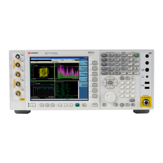
About the EMI Receiver Measurement Application About the EMI Receiver Measurement Application This book provides information on using the EMI Receiver Mode in your MXE EMI Receiver or your X-Series Signal Analyzer. The MXE EMI Receiver allows you to make fully CISPR compliant measurements. The X-Series signal analyzers allow you to make the same measurements in a precompliance environment.
About the EMI Receiver Measurement Application The Role of Precompliance in the Product Development Cycle The Role of Precompliance in the Product Development Cycle To ensure successful electromagnetic interference (EMI) compliance testing, precompliance testing has been added to the development cycle. In precompliance testing, the electromagnetic compatibility (EMC) performance is evaluated from design through production units.
Conducted Emissions Measurement Examples Conducted Emissions Measurement Examples Conducted emissions testing focuses on emissions that are conducted along a power line that are generated by the device under test (DUT). The transducer that is typically used to couple the emissions of the power line to the EMI Receiver is a line impedance stabilization network (LISN).
Conducted Emissions Measurement Examples Making Conducted Emission Measurements Making Conducted Emission Measurements CAUTION Before connecting a signal to the MXE receiver, make sure the instrument can safely accept the signal level provided. The signal level limits are marked next to the RF Input connectors on the front panel.
Page 11
Conducted Emissions Measurement Examples Making Conducted Emission Measurements Step Action Notes The limit line will be turned on after 5 Load Quasi-peak limit line a. Press Recall, Data, Limit, loading, If no data exists for Trace 1, Limit, Select Limit, Limit the Limit Line will not display.
Page 12
Conducted Emissions Measurement Examples Making Conducted Emission Measurements Step Action Notes 7 Change EMI Average a. Press Meas Setup, detector to compare to Limit Detectors (Measure). Line 2 b. Select Detector, Detector c. Press Limit for Δ, Limit 2, A dialog box may appear, Enter.
Page 13
Conducted Emissions Measurement Examples Making Conducted Emission Measurements Step Action Notes 11 Stop the scan a. Press Stop.
Page 14
Conducted Emissions Measurement Examples Making Conducted Emission Measurements Running Frequency Scan Step Action Notes 1 Turn on the DUT a. Configure the LISN and DUT. b. Turn the DUT on. Ensure that the power cord 2 Set Up a. Connect the DUT and LISN, to the between the DUT and the LISN EMI Receiver as shown below: is as short as possible.
Page 15
Conducted Emissions Measurement Examples Making Conducted Emission Measurements Step Action Notes Adding signals to the signal list Step Action Notes 1 Clear any existing signal a. Press Meas Setup, Signal List, list Delete Signals, Delete All. 2 Switch to search a.
Page 17
Conducted Emissions Measurement Examples Making Conducted Emission Measurements Measuring the Quasi-peak and average values of the signals Step Action Notes 1 Perform a Re-measure on a. Press Meas Setup, Scan. all signals in the list Sequence, (Re)measure, (Re)measure, All Signals, Sweep/Control, Start.
Page 18
Conducted Emissions Measurement Examples Making Conducted Emission Measurements...
Radiated Emissions Measurement Examples Radiated Emissions Measurement Examples Radiated emissions measurements are not as straightforward as conducted emissions measurements. There is the added complexity of the ambient environment, which could interfere with measuring the emissions from the device under test (DUT).
Radiated Emissions Measurement Examples Making Radiated Emission Measurements Making Radiated Emission Measurements CAUTION Before connecting a signal to the MXE receiver, make sure the instrument can safely accept the signal level provided. The signal level limits are marked next to the RF Input connectors on the front panel.
Page 21
Radiated Emissions Measurement Examples Making Radiated Emission Measurements Step Action Notes T I P 2 Turn on the instrument. a. Press the front-panel power key. This is the default mode. 3 Select the EMI mode. a. Press Mode, EMI receiver. Deselect any range that has a green 4 Open the scan table and a.
Page 22
Radiated Emissions Measurement Examples Making Radiated Emission Measurements Step Action Notes 6 Load limit lines a. Press Recall, Data, Limit (Preloaded 1), Open. b. Scroll to EN 55022, Rad, Class A, 30 MHz to 1 GHz (10m).csv, Open. 7 Load correction factors for a.
Page 23
Radiated Emissions Measurement Examples Making Radiated Emission Measurements Running Frequency Scan Step Action Notes 1 Clear any existing a. Press Meas Setup, Signal signal list List, Delete Signals, Delete All. 2 Turn on the DUT and a. Turn the DUT on. start frequency scan b.
Page 24
Radiated Emissions Measurement Examples Making Radiated Emission Measurements Adding signals to the list Step Action Notes This is the default value. 1 Set the search criteria a. Press Meas Setup, More 1 of 2, to peak criteria and Limits, Search Criteria, Peak limits Criteria and Limits.
Page 25
Radiated Emissions Measurement Examples Making Radiated Emission Measurements Measuring the Quasi-peak and average values of the signals Step Action Notes 1 Measure remaining a. Press Meas Setup, Scan signals Sequence, (Re)measure, (Re)measure All Signals. b. Press Sweep/Control, Start. 2 Review the measurement results...
Page 26
Radiated Emissions Measurement Examples Making Radiated Emission Measurements...
Disturbance Analyzer (Click) Measurements Disturbance Analyzer (Click) Measurements The following topics are in this section: “Overview” on page 28 “Making a Measurement” on page 29 “Quick Reference to Menus” on page 36 “Setup Table Menu Features” on page 38...
Disturbance Analyzer (Click) Measurements Overview Overview A broad range of commercially-available electronic devices exhibit intermittent operation that generates impulsive (or discontinuous) radiated and conducted disturbances. Common examples of these devices are washing machines, refrigerators, thermostats, motor-operated apparati, and automatic dispensing machines.
Disturbance Analyzer (Click) Measurements Making a Measurement Making a Measurement Setting up a Click measurement Step Action Notes 1 Turn on the receiver a. Press the front-panel power key. 2 Test Set Up a. Configure the Device Under Test (DUT) b.
Page 30
Disturbance Analyzer (Click) Measurements Making a Measurement Step Action Notes From this display you can: —View the status of a data collection in progress. —Access the navigation and editing features of the disturbance list. —Access the measurement setup table This table enables you to configure the 4 Access the Setup a.
Page 31
Disturbance Analyzer (Click) Measurements Making a Measurement Setting up the Disturbance Analyzer measurement The Click measurement can be set up using either the Setup Table screen, the menu keys or a combination of both. The following procedure guides you through the measurement using the menu keys.
Page 32
Disturbance Analyzer (Click) Measurements Making a Measurement Step Action Notes For more information see “Limit” on 3 If a manual limit a. Press Limit to select Man page choice is desired and enter the desired value using the numeric keypad. b.
Page 33
Disturbance Analyzer (Click) Measurements Making a Measurement Step Action Notes For more information see “Click Count” on 7 If desired, set the a. Press Click Count to page number of clicks as a select On. limit for data b. Enter the desired value collection using the numeric keypad and select the Enter key.
Page 34
Disturbance Analyzer (Click) Measurements Making a Measurement Step Action Notes Final analysis 11 Create a report a. Press Save, Data, Meas Result To edit each of the header elements, press the associated softkey and type in your information using either a keyboard or the built-in text editor.
Page 35
Disturbance Analyzer (Click) Measurements Making a Measurement Step Action Notes 12 Save the report a. Press Return, Save As. b. Enter the filename and location into the Save dialog box. c. Press Save. 13 Return to a. Press Meas Setup. Measurement screen...
Disturbance Analyzer (Click) Measurements Setup Table Menu Features Setup Table Menu Features Frequency CISPR 14 requires that discontinuous disturbance measurements be made at 4 frequencies: 150kHz, 500kHz, 1.4 MHz and 30 MHz. The MXE allows you to select these default frequencies or to enter a non-standard measurement frequency. Terminal CISPR 14 defines limits based on the terminals at which the measurements are made.
Page 39
Disturbance Analyzer (Click) Measurements Setup Table Menu Features Click Rate The click rate (N) is the key metric used to determine the click limit Lq. The click rate is determined by counting the number of clicks per minute. The determination of N is based on whether you are using continuous operation or switching cycles to collect clicks.
Page 40
Disturbance Analyzer (Click) Measurements Setup Table Menu Features Factor f For certain types of products that must be cycled to emit discontinuous disturbances (rather than run continuously), CISPR 14-1 requires users to operate the product over enough cycles to product 40 clicks. Factor f is used to calculate the click rate for these types of devices.
Saving Data Saving Data The following topics are in this section: “Overview” on page 42 “Export Data Menu Details” on page 42 “Data file examples” on page 43...
Saving Data Overview Overview Saving Data (Data Export) stores data from the current measurement to mass storage files. The Export Menu only contains data types that are supported by the current measurement. The following graphics displays the Save Data menu for the EMI Receiver Mode. Note that some of the selections have "hollow points"...
Page 43
Saving Data Overview returns back to the Export Data menu and the selected Correction “Correction Data File” on number is annotated on the key. See page Trace The trace file contains "meta" data which describes the current setting of the receiver, but it is not the full state of the receiver. You can select Traces 1, 2 3, or All.
Saving Data Overview Monitor Spectrum (IF Mode0 Trace Data File Limit Data Files .csv file format The Amplitude Unit line in the limits file may contain an antenna factor unit, for example: Amplitude Unit=dBuV/m...
Page 48
Saving Data Overview Antenna factor units are dBuV/m, dBuA/m, dBpT, and dBG. In this case, the unit is treated exactly as though it were dBuV, meaning that all of the limits are interpreted to have units of dBuV. The box does NOT change Y Axis Units when such a limit is loaded in.
Saving Data Overview Scan Table Data File Meas Results Data Files The keys correspond to the sections in the Meas Results Contents form as shown below:...
Page 51
Saving Data Overview Trace This key/section enables you to customize the trace related information to be added to the report. You can also select whether settings and Trace data will be part of the output by turning the selections On or Off. Amptd Corr This key/section enables you to choose whether to show only the file name and description or the Amplitude Correction complete data by turning the selections On...
Page 52
Saving Data Overview Signal List This key/selection enables you to choose whether or not to show the Signal List information in the report. Output Format This key/selection enables you to select the output format of Measurement Results. If the Output Format is set to HTML, a .html file will be saved and a directory that contains the .png file for the screen image will be created.
Line Impedance Stabilization Networks (LISN) A: Line Impedance Stabilization Networks (LISN) A line impedance stabilization network serves three purposes: 1. The LISN isolates the power mains from the device under test. the power supplied to the DUT must be as clean a possible. Any noise on the line will be coupled to the EMI Receiver and interpreted as noise generated by the DUT 2.
Line Impedance Stabilization Networks (LISN) LISN Operation LISN Operation The following graphic shows a typical LISN circuit diagram for one side of the line relative to earth ground. The chart represents the impedance of the DUT port versus frequency. The 1 μF in combination with the 50 μH inductor is the filter that isolates the mains from the DUT.
LISN. Switching DUT power on or off can cause large spikes generated in the LISN. The Keysight 11947A transient limiter incorporates a limiter, high-pass filter, and an attenuator. It can withstand 10 kW for 10 μsec and has a frequency range of 9 kHz to 200 MHz.
Page 56
Line Impedance Stabilization Networks (LISN) Types of LISNs...
Antenna Factors Field Strength Units Field Strength Units Radiated EMI emissions measurements measure the electric field. The field strength is calibrated in dBμV/m. Field strength in dBμV/m is derived from the following: Pt = total power radiated from an isotropic radiator PD = the power density at a distance r from the isotropic radiator (far field) PD = Pt /4πr2 R = 120mΩ...
Page 59
Antenna Factors Field Strength Units Types of antennas used for commercial radiated measurements There are three types of antennas used for commercial radiated emissions measurements: • Biconical antenna: 30 MHz to 300 MHz • Log periodic antenna: 200 MHz to 1 GHz (the biconical and log periodic overlap frequency) •...
Basic Electrical Relationships C: Basic Electrical Relationships The decibel is used extensively in electromagnetic measurements. It is the log of the ratio of two amplitudes. The amplitudes are in power, voltage, amps, electric field units and magnetic field units. decibel = dB = 10 log (P2/P1) Data is sometimes expressed in volts or field strength units.
Detectors Used in EMI Measurements Peak Detector Peak Detector Initial EMI measurements are made using the peak detector. This mode is much faster than quasi-peak, or average modes of detection. Signals are normally displayed on spectrum analyzers or EMC analyzers in peak mode. Since signals measured in peak detection mode always have amplitude values equal to or higher than quasi-peak or average detection modes, it is a very easy process to take a sweep and compare the results to a limit line.
Detectors Used in EMI Measurements Quasi-peak Detector Quasi-peak Detector Most radiated and conducted limits are based on quasi-peak detection mode. Quasi-peak detectors weigh signals according to their repetition rate, which is a way of measuring their annoyance factor. As the repetition rate increases, the quasi-peak detector does not have time to discharge as much, resulting in a higher voltage output.
Detectors Used in EMI Measurements Average Detector Average Detector The average detector is required for some conducted emissions tests in conjunction with using the quasi-peak detector. Also, radiated emissions measurements above 1 GHz are performed using average detection. The average detector output is always less than or equal to peak detection.
Page 68
Ambient level 1. The values of radiated and conducted signal and noise existing at a specified test location and time when the test sample is not activated 2. Those levels of radiated and conducted signal and noise existing at a specified test location and time when the test sample is inoperative.
Page 69
Antenna terminal conducted interference Any undesired voltage or current generated within a receiver, transmitter, or their associated equipment appearing at the antenna terminals. Auxiliary equipment Equipment not under test that is nevertheless indispensable for setting up all the functions and assessing the correct performance of the EUT during its exposure to the disturbance.
Page 70
Dipole 1. An antenna consisting of a straight conductor usually not more than a half-wavelength long, divided at its electrical center for connection to a transmission line. 2. Any one of a class of antennas producing a radiation pattern approximating that of an elementary electric dipole.
Page 71
Immunity 1. The property of a receiver or any other equipment or system enabling it to reject a radio disturbance. 2. The ability of electronic equipment to withstand radiated electromagnetic fields without producing undesirable responses. Intermodulation Mixing of two or more signals in a nonlinear element, producing signals at frequencies equal to the sums and differences of integral multiples of the original signals.
Page 72
RFI is the high frequency interference with radio reception. This occurs when undesired electromagnetic oscillations find entrance to the high frequency input of a receiver or antenna system. RFI sources Sources are equipment and systems as well as their components which can cause RFI.
Need help?
Do you have a question about the X Series and is the answer not in the manual?
Questions and answers