Table of Contents
Advertisement
Quick Links
Honeywell International, Inc.
9201-B San Mateo Blvd N.E.
Albuquerque, New Mexico 87113 U.S.A.
Telephone: 855-250-7027 (Toll Free U.S.A./Canada)
Telephone: 602-365-7027 (International Direct)
XVUE TOUCH PRIMARY FLIGHT DISPLAY SYSTEM
INSTALLATION MANUAL
FOR USE IN NON-CERTIFIED AIRCRAFT
Document P/N 89000109-002 Rev 2
November 2019
This document contains technical data and is subject to U.S. export regulations. These commodities,
Export Control
technology, or software were exported from the United States in accordance with the export
administration regulations. Diversion contrary to U.S. law is prohibited.
ECCN: 7E994
© Honeywell International Inc. Do not copy without express permission of Honeywell.
Advertisement
Chapters
Table of Contents
Troubleshooting

Related Manuals for BENDIXKing XVUE TOUCH


Summary of Contents for BENDIXKing XVUE TOUCH
- Page 1 Honeywell International, Inc. 9201-B San Mateo Blvd N.E. Albuquerque, New Mexico 87113 U.S.A. Telephone: 855-250-7027 (Toll Free U.S.A./Canada) Telephone: 602-365-7027 (International Direct) XVUE TOUCH PRIMARY FLIGHT DISPLAY SYSTEM INSTALLATION MANUAL FOR USE IN NON-CERTIFIED AIRCRAFT Document P/N 89000109-002 Rev 2 November 2019 This document contains technical data and is subject to U.S.
- Page 2 For Use in Non-Certified Aircraft Legal Notice Proprietary Information Honeywell - Confidential THIS COPYRIGHTED WORK AND ALL INFORMATION ARE THE PROPERTY OF HONEYWELL INTERNATIONAL INC., CONTAIN TRADE SECRETS AND MAY NOT, IN WHOLE OR IN PART, BE USED, DUPLICATED, OR DISCLOSED FOR ANY PURPOSE WITHOUT PRIOR WRITTEN PERMISSION OF HONEYWELL INTERNATIONAL INC.
- Page 3 For Use in Non-Certified Aircraft (4) Assignment And Transfer - This License Agreement may be assigned to a formally designated service designee or transferred to a subsequent owner or operator of an airplane containing the subject Honeywell aerospace products. However, the recipient of any such assignment or transfer must assume all of your obligations under this License Agreement.
- Page 4 For Use in Non-Certified Aircraft Safety Advisory WARNING: BEFORE THE MATERIALS CALLED OUT IN THIS PUBLICATION ARE USED, KNOW THE HANDLING, STORAGE AND DISPOSAL PRECAUTIONS RECOMMENDED BY THE MANUFACTURER OR SUPPLIER. FAILURE TO OBEY THE MANUFACTURERS’ OR SUPPLIERS’ RECOMMENDATIONS CAN RESULT IN PERSONAL INJURY OR DISEASE.
- Page 5 To download or view publications online 1. To tell BendixKing of a possible data error in a publication. 2. Changes to this manual are provided to users who have registered via the xVue Touch website to receive updates. BendixKing Customer Support If you need to speak to personnel about Technical matters, the BendixKing Customer Support team provides 24/7 customer service.
- Page 6 For Use in Non-Certified Aircraft RECORD OF REVISIONS NOTE: The revision level for every page of this document will be updated during the revision process. A list of effective pages is, therefore, not required. Revision Revision Date Description 11Apr2018 Initial release 29June2018 Rewritten to update design details throughout 06Nov2019...
-
Page 7: Table Of Contents
2.10 Required GPS Navigator ......................... 2-21 2.11 Installation Limitations ........................2-21 2.12 Permission ............................2-23 2.13 Repair and Return .......................... 2-23 3 XVUE TOUCH SYSTEM INSTALLATION OVERVIEW ........3-1 3.1 Pre-Installation Checklist........................3-3 3.2 Available Equipment .......................... 3-5 3.3 Installation Materials.......................... 3-5 3.3.1 Accessories and Support Equipment Available from BendixKing............ - Page 8 3.5.1.2 Serial I/O............................. 3-14 3.5.1.3 ARINC 429 I/O..........................3-14 3.5.1.4 ARINC 453 I/O..........................3-14 3.6 Installation Considerations....................... 3-14 3.6.1 xVue Touch System Interfaces ...................... 3-15 3.6.2 Instrument Panel........................... 3-18 3.6.3 Standby Instruments ........................3-19 3.6.3.1 Standby Instrument Location ..................... 3-19 3.6.3.2 Standby Attitude Indicator ......................
- Page 9 4.9 KTP 73 Installation..........................4-19 4.9.1 KTP 73 Installation Procedures...................... 4-19 4.9.2 KTP 73 - Post Installation Unit Verification ................... 4-20 4.10 xVue Touch System Components and Wiring Location Data ............4-20 4.10.1 Wiring Harness ..........................4-20 4.11 Weight and Balance Analysis......................4-21 4.12 Aircraft Electrical Load Analysis (ELA) ....................
- Page 10 6.4 KMG 7010/MD32 Calibration (Magnetometer) ................6-47 6.4.1 Magnetometer Installation Orientation..................6-49 6.4.2 Magnetometer Compensation...................... 6-51 6.5 KTP 73 Configuration (Outside Air Temperature Probe)..............6-53 89000109-002 xVue Touch Installation Manual Rev 2 Page T-4 © Honeywell International Inc. Do not copy without express permission of Honeywell.
- Page 11 For Use in Non-Certified Aircraft 7 SYSTEM CHECKOUT ..................7-1 7.1 Recommended Test Equipment ......................7-1 7.2 xVue Touch System Post Installation System Checkout ..............7-1 7.2.1 Attitude Checkout ........................... 7-2 7.2.2 Heading Checkout ........................... 7-2 7.2.3 Leak Test............................7-2 7.2.4 Altitude Display/Vertical Display and Standby Altimeter Checkout..........
- Page 12 9.2.4.2 Screen Cleaning ..........................9-2 9.2.4.3 IR Bar Cleaning ..........................9-2 9.2.4.4 Inspection............................. 9-3 9.2.4.5 Configuration Module Inspection ....................9-3 9.2.4.6 xVue Touch System Bonding Inspection ..................9-3 9.2.4.7 Inspection Criteria ........................9-4 9.2.4.8 Adjustments ..........................9-8 9.2.4.9 Testing ............................9-8 9.2.4.10 Lubrication..........................
- Page 13 LIST OF FIGURES Figure 1-1 Symbols ........................1-1 Figure 2-1 xVue Touch System Components................2-2 Figure 2-2 xVue Touch System Block Diagram ................2-3 Figure 2-3 Standby Instrument Power Requirements.............. 2-22 Figure 3-1 Example Instrument Panel Modification..............3-1 Figure 3-2 xVue Touch System Interfaces ................3-15 Figure 3-3 KSD 100EXP Primary Field of View ................
- Page 14 Figure 6-53 KMG 7010 Calibration Page .................. 6-49 Figure 6-54 X, Y, Z Axis Positive Direction ................6-50 Figure 6-55 KMG 7010/MD32 Calibration Reading ..............6-52 89000109-002 xVue Touch Installation Manual Rev 2 Page T-2 © Honeywell International Inc. Do not copy without express permission of Honeywell.
- Page 15 Figure 7-44 Software Loading Pop-Up Window (Loading Complete)........7-33 Figure 7-45 Software Loading Pop-Up Window (Power Cycle) ..........7-33 89000109-002 xVue Touch Installation Manual Rev 2 Page T-3 © Honeywell International Inc. Do not copy without express permission of Honeywell.
- Page 16 Figure B-9 KG 71 LRU Interconnect Diagram - 3................. B-9 Figure B-10 KG 71 LRU Interconnect Diagram - 4..............B-10 Figure C-1 xVue Touch System Components and Cable Routing (Top View) ......C-2 Figure C-2 xVue Touch System Components and Cable Routing (Side View) ......C-3 Figure C-3 xVue Touch System Circuit Breakers and Switch Locations ........
- Page 17 Table 2-15 KDC 100EXP Environmental Qualification Form (EQF) ..........2-18 Table 2-16 KTP 73 Environmental Qualification Form (EQF)............. 2-18 Table 2-17 xVue Touch System Component Regulatory Compliance ........2-19 Table 3-1 Pre-Installation Checklist ..................... 3-3 Table 3-2 xVue Touch System Components and Kits ..............3-5 Table 3-3 Installation Kit, Backshell Assembly –...
- Page 18 Table 4-1 Configuration Module (J2 Backshell) Pin Descriptions ..........4-5 Table 4-2 Wiring Harness Equipment..................4-21 Table 4-3 xVue Touch System Component Weights & Centers of Gravity........ 4-21 Table 4-4 Typical LRU Current Draw..................4-23 Table 5-1 KSD 100EXP J1 Pin Descriptions (Viewed from LRU) ........... 5-1 Table 5-2 KSD 100EXP J2 Pin Descriptions (Viewed from LRU) ...........
-
Page 19: Introduction
Handle the items susceptible to electrostatic discharge in accordance with MIL-HDBK-263. Refer to MIL- STD-1686 for definition of the standards and conditions. 89000109-002 xVue Touch Installation Manual Rev 2 Page 1-1 © Honeywell International Inc. Do not copy without express permission of Honeywell. -
Page 20: References
For Use in Non-Certified Aircraft 1.2 References 1.2.1 BendixKing/Vendor Publications The publications listed in Table 1-1 are BendixKing/Vendor references. Check for latest version of publication. Table 1-1 BendixKing/Vendor References Document Number Description D201804000013 xVue Touch Pilot’s Guide 89800109-004 xVue Touch Airplane Flight Procedures (AFP) -
Page 21: Acronyms And Abbreviations
Automatic Dependent Surveillance AFCS Automatic Flight Control System Airplane Flight Manual AHRS Attitude and Heading Reference System Attitude Indicator Altitude 89000109-002 xVue Touch Installation Manual Rev 2 Page 1-3 © Honeywell International Inc. Do not copy without express permission of Honeywell. - Page 22 Center of Gravity Configuration Module Command Configuration and Maintenance Tool COMP Composite Central Processing Unit Course Design Assurance Level Direct Current 89000109-002 xVue Touch Installation Manual Rev 2 Page 1-4 © Honeywell International Inc. Do not copy without express permission of Honeywell.
- Page 23 Government Printing Office Global Positioning System Glideslope Heading Horizontal Situation Indicator Input/Output Instructions for Continued Airworthiness Identification International Electrotechnical Commission 89000109-002 xVue Touch Installation Manual Rev 2 Page 1-5 © Honeywell International Inc. Do not copy without express permission of Honeywell.
- Page 24 NAVAID Navigational Aid NEMA National Electrical Manufacturers Association Number Newton Meter Non-Volatile Memory Outside Air Temperature Primary Flight Display 89000109-002 xVue Touch Installation Manual Rev 2 Page 1-6 © Honeywell International Inc. Do not copy without express permission of Honeywell.
- Page 25 Terrain Awareness and Warning System Type Certificate TCDS Type Certificate Data Sheet TIS-B Traffic Information Service-Broadcast Technical Standard Order Transmit 89000109-002 xVue Touch Installation Manual Rev 2 Page 1-7 © Honeywell International Inc. Do not copy without express permission of Honeywell.
-
Page 26: Terminology
For the purposes of this installation manual, “metal” airplane refers to airplane with an aluminum skin. Non-metallic aircraft refers to all other aircraft, fiberglass or composite skin and aircraft with tube and fabric construction. 89000109-002 xVue Touch Installation Manual Rev 2 Page 1-8 © Honeywell International Inc. Do not copy without express permission of Honeywell. -
Page 27: General Information
Touch System. The information in this document is subject to change without notice. To download or view publications online, visit the Honeywell Online Technical Publications Website (https:// myaerospace.honeywell.com/). -
Page 28: Xvue Touch Overview
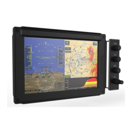
2.3 xVue Touch Overview The xVue Touch System is a touch-controlled Smart Primary Flight Display (PFD) and Multifunction Display (MFD) that replaces the traditional 6- and 8-pack flight instruments. The xVue Touch System is illustrated in Figure 2-1 and consists of:... -
Page 29: Ksd 100Exp Primary Flight Display
Map, VFR Sectional and IFR charts, Instrument Procedures charts, Synthetic Vision, and ADS-B Traffic and Weather. The xVue Touch System may also be referenced throughout this document as KFD 900EXP or abbreviated to KFD 900. Figure 2-2 xVue Touch System Block Diagram 2.3.1 KSD 100EXP Primary Flight Display... -
Page 30: Kg 71Exp Air Data Attitude Heading Reference System (Adahrs)
The KG 71EXP provides attitude, altitude, airspeed, air temperature, vertical speed and heading information for the xVue Touch System. The air data parameters are calculated based on total pressure, static pressure, and air temperature. The attitude and heading reference system provides current airplane attitude based on inertial sensors and an aiding source (GPS or airspeed). -
Page 31: Ktp 73 Oat Probe
Cooling Convection cooled (does not required forced air cooling within the unit operational temperature range) Connectors Male 9-pin D-Sub 89000109-002 xVue Touch Installation Manual Rev 2 Page 2-5 © Honeywell International Inc. Do not copy without express permission of Honeywell. -
Page 32: Table 2-4 Kg 71Exp Adahrs Specifications
DO 334 Category T3 Turn Rate Output Range ±128 Degrees/Second Max Pitch/Roll/Yaw Rate ± 245 deg/sec Max Sustained G ± 4g 89000109-002 xVue Touch Installation Manual Rev 2 Page 2-6 © Honeywell International Inc. Do not copy without express permission of Honeywell. -
Page 33: Table 2-6 Kmg 7010 Magnetometer Specifications
Operating Voltage 7.0 to 32 VDC Output Data ARINC 429 (proprietary format) Mating Connector MCI P/N 8017287 Certifications TSO-C6e 89000109-002 xVue Touch Installation Manual Rev 2 Page 2-7 © Honeywell International Inc. Do not copy without express permission of Honeywell. -
Page 34: Table 2-8 Kdc 100Exp Data Converter Specifications
Mounted outside the airplane. No cooling required. Connectors 5 ft. 3-conductor shielded wire lead, spliced into AC wiring harness. Certifications TSO-C106 (Incomplete) 89000109-002 xVue Touch Installation Manual Rev 2 Page 2-8 © Honeywell International Inc. Do not copy without express permission of Honeywell. -
Page 35: Environmental Qualification Form (Eqf)
For Use in Non-Certified Aircraft 2.5 Environmental Qualification Form (EQF) The following table provides the DO-160G Environmental categories for the xVue Touch System components. Table 2-10 KSD 100EXP Environmental Qualification Form (EQF) DO-160G Conditions Category Notes Section Temperature and Altitude A1/C1 -20°C/+55°C, -40°C/+70°C Short Term,... - Page 36 Cat D 6 - 8 GHz Cat D 8 - 12 GHz Cat D 12 - 18 GHz Cat D 89000109-002 xVue Touch Installation Manual Rev 2 Page 2-10 © Honeywell International Inc. Do not copy without express permission of Honeywell.
-
Page 37: Table 2-11 Kcp 100Exp Environmental Qualification Form (Eqf)
Lightning Induced Transient Susceptibility A3J3L3 23.0 Lightning Direct Effects 24.0 Icing 25.0 Electrostatic Discharge 26.0 Flammability (See Note 3) 89000109-002 xVue Touch Installation Manual Rev 2 Page 2-11 © Honeywell International Inc. Do not copy without express permission of Honeywell. - Page 38 Cat D 6 - 8 GHz Cat D 8 - 12 GHz Cat D 12 - 18 GHz Cat D 89000109-002 xVue Touch Installation Manual Rev 2 Page 2-12 © Honeywell International Inc. Do not copy without express permission of Honeywell.
-
Page 39: Table 2-12 Kg 71Exp Environmental Qualification Form (Eqf)
Lightning Induced Transient Susceptibility A3J3L3 23.0 Lightning Direct Effects 24.0 Icing 25.0 Electrostatic Discharge 26.0 Flammability (See Note 3) 89000109-002 xVue Touch Installation Manual Rev 2 Page 2-13 © Honeywell International Inc. Do not copy without express permission of Honeywell. - Page 40 Cat D 7. The Outside Air Temperature (OAT) parameter was tested to DO-160G Category R for both (CS) and (RS). 89000109-002 xVue Touch Installation Manual Rev 2 Page 2-14 © Honeywell International Inc. Do not copy without express permission of Honeywell.
-
Page 41: Table 2-13 Kmg 7010 Environmental Qualification Form (Eqf)
20.0 Radio Frequency Susceptibility (Radiated and Conducted) 21.0 Emission or Radio Frequency Energy 22.0 Lightning Induced Transient Susceptibility A4J33 89000109-002 xVue Touch Installation Manual Rev 2 Page 2-15 © Honeywell International Inc. Do not copy without express permission of Honeywell. - Page 42 89000109-002 xVue Touch Installation Manual Rev 2 Page 2-16 © Honeywell International Inc. Do not copy without express permission of Honeywell.
-
Page 43: Table 2-14 Md32 Environmental Qualification Form (Eqf)
Electrostatic Discharge (ESD) Fire, Flammability Notes: Sections 20: Radiated susceptibility complies with Category G from 100-400MHz and Category F from 400-18,000MHz. 89000109-002 xVue Touch Installation Manual Rev 2 Page 2-17 © Honeywell International Inc. Do not copy without express permission of Honeywell. -
Page 44: Table 2-15 Kdc 100Exp Environmental Qualification Form (Eqf)
22.0 Lightning Induced Transient Susceptibility 23.0 Lightning Direct Effects XX2A 24.0 Icing 25.0 Electrostatic Discharge 26.0 Flammability Analysis Only 89000109-002 xVue Touch Installation Manual Rev 2 Page 2-18 © Honeywell International Inc. Do not copy without express permission of Honeywell. -
Page 45: Regulatory Compliance
For Use in Non-Certified Aircraft 2.6 Regulatory Compliance Table 2-17 xVue Touch System Component Regulatory Compliance Component Function Approval Type KSD 100EXP Display KCP 100EXP Display Control KG 71EXP Air Data, Attitude and Heading Computer KTP 73 Temperature Probe TSO-C106 INCOMP... -
Page 46: Databases
Runways depictions are further detailed with a runway identifier, centerline, threshold markings, and 89000109-002 xVue Touch Installation Manual Rev 2 Page 2-20 © Honeywell International Inc. Do not copy without express permission of Honeywell. -
Page 47: Recommended Standby Instruments
2.10 Required GPS Navigator Installation of the xVue Touch System requires at least one GPS/SBAS navigator. The xVue Touch System has the capability to support dual navigator installations. Refer to Table 3-22 for a list of compatible navigators. -
Page 48: Figure 2-3 Standby Instrument Power Requirements
For Use in Non-Certified Aircraft Figure 2-3 Standby Instrument Power Requirements 89000109-002 xVue Touch Installation Manual Rev 2 Page 2-22 © Honeywell International Inc. Do not copy without express permission of Honeywell. -
Page 49: Permission
2.13 Repair and Return Refer to the troubleshooting instructions in Section 8 Troubleshooting. If repair is necessary, the unit must be sent to a BendixKing certificated repair facility. The xVue Touch System components are not field repairable. For information on returning a unit, contact BendixKing support. -
Page 50: Xvue Touch System Installation Overview
Read the entire sections before beginning the work. Prior to installation, consider the structural integrity of each component of the xVue Touch System as defined in Section 4. Review the airplane logbooks for all equipment that are installed in the airplane to ensure complementing equipment remains installed and to allow for proper systems operation. - Page 51 CONDUCTIVE SURFACE AND DISCHARGE PATHS. USE STANDARD INDUSTRY PRECAUTIONS TO KEEP RISK OF DAMAGE TO A MINIMUM WHEN REMOVING, SERVICING, OR HANDLING THE EQUIPMENT. 89000109-002 xVue Touch Installation Manual Rev 2 Page 3-2 © Honeywell International Inc. Do not copy without express permission of Honeywell.
-
Page 52: Pre-Installation Checklist
For Use in Non-Certified Aircraft 3.1 Pre-Installation Checklist Before beginning a xVue Touch System installation, it is important to ensure the airplane meets the pre- requisites for the installation of the xVue Touch System. The following checklist is provided to aid the installer in determining the necessary requirements that must be met before beginning installation of the xVue Touch System in a specific airplane. - Page 53 AFP for operational limitations Airplane electrical system is sufficient for xVue Touch. Section 4.12 Aircraft Electrical Load Analysis (ELA) Airplane weight and balance with xVue Touch addition is Section 4.11 Weight and Balance available. Analysis 89000109-002 xVue Touch Installation Manual...
-
Page 54: Available Equipment
For Use in Non-Certified Aircraft 3.2 Available Equipment The xVue Touch System may be configured based on the combinations of equipment and install kits shown in Table 3-2. Table 3-2 xVue Touch System Components and Kits Description KSD 100EXP Primary Flight Display... -
Page 55: Table 3-4 Installation Kit, Configuration Module & Connectors - Ksd 100Exp, Pn 89000120-003
KCP 100 Center Stack Adapter MS51957-33 #6-32 X 7/8 inch Pan Head Screw 089-02353-0001 #6-32 Self Locking Clip Nut 89000109-002 xVue Touch Installation Manual Rev 2 Page 3-6 © Honeywell International Inc. Do not copy without express permission of Honeywell. -
Page 56: Table 3-8 Kg 71Exp Installation Kit Pn 89000123-007
Connector, D-Sub, Receptacle, Hsg, Brass Shell, 9- Table 3-11 KDC 100EXP Installation Kit PN 89000138-002 Part Number Description 53505633-1 Connector, D-Sub 89000109-002 xVue Touch Installation Manual Rev 2 Page 3-7 © Honeywell International Inc. Do not copy without express permission of Honeywell. -
Page 57: Accessories And Support Equipment Available From Bendixking
3.3.2 Materials Required but Not Supplied The xVue Touch System is intended for use with standard aviation accessories. The following items are required for installation but not supplied: Table 3-13 Installation Materials Required but Not Supplied... - Page 58 As Required Conversion coating Thread-seal tape (PTFE) Commercially As Required Available Self-Fusing Silicon Tape, 3M 83010 Commercially As Required Available 89000109-002 xVue Touch Installation Manual Rev 2 Page 3-9 © Honeywell International Inc. Do not copy without express permission of Honeywell.
-
Page 59: Tools Required But Not Supplied
D-sub 9 Pin Socket and Pin Connector Tools for the KCP 100EXP Control Panel Installation Kit (89000126-004) M81969/1-02 Red and White Metal Insert/Removal Tools AFM8 Crimp Tool M22520/2-01 89000109-002 xVue Touch Installation Manual Rev 2 Page 3-10 © Honeywell International Inc. Do not copy without express permission of Honeywell. -
Page 60: Unpacking And Inspection
Table 3-2, for the appropriate part lists. Inspect all components for any damage, contact BendixKing Customer Support if any parts are missing or damaged. The shipping container and all packing materials must be retained in the event that storage or reshipment of the equipment is necessary. -
Page 61: System Interfaces
Open Circuit Table 3-18 KSD 100EXP Discrete Input 28V/Open (DI28VO) States State Voltage Level Active 28 VDC Inactive Open Circuit 89000109-002 xVue Touch Installation Manual Rev 2 Page 3-12 © Honeywell International Inc. Do not copy without express permission of Honeywell. -
Page 62: Discrete Outputs
In general, equipment must be installed in a location convenient for operation, inspection, and maintenance, and in an area free from excessive vibration, heat, and EMI noise generating sources. The location consideration for each of the xVue Touch System components is described in this section. 89000109-002... -
Page 63: Figure 3-2 Xvue Touch System Interfaces
For Use in Non-Certified Aircraft Figure 3-2 xVue Touch System Interfaces 89000109-002 xVue Touch Installation Manual Rev 2 Page 3-14 © Honeywell International Inc. Do not copy without express permission of Honeywell. -
Page 64: Xvue Touch System Interfaces
For Use in Non-Certified Aircraft 3.6.1 xVue Touch System Interfaces The xVue Touch System components can interface with a variety of other avionics equipment. The following list includes the proven interfaces. There may be other devices that can be configured the same as the ones listed below but have not been tested by BendixKing. - Page 65 For Use in Non-Certified Aircraft Table 3-22 xVue Touch Compatible Equipment Category Vendor Model GPS Navigators BendixKing KSN 765 Garmin GNC 420W GPS 400W GPS 500W GTN 625 GTN 635 GTN 725 Avidyne IFD 410 IFD 510 IFD 545 Radio Navigators...
-
Page 66: Instrument Panel
For Use in Non-Certified Aircraft Table 3-22 xVue Touch Compatible Equipment Category Vendor Model Magnetometer BendixKing KMG 7010 Magnetometer MidContinent Instruments MD32 + Avionics Data Converter BendixKing KDC 100EXP OAT Probe BendixKing KTP 73 NOTE GPS DATA IS AVAILABLE FROM KSN 770/765 NAVIGATORS THROUGH A RS-232 OUTPUT BUS (P-EXPRESS BUS). -
Page 67: Standby Instruments
The instrument panel must be aluminum to meet the electrical bonding requirements between the KSD 100EXP unit and the airplane panel, reference Section 3.10. The xVue Touch system equipment dimensions and installation templates are provided in Appendix A Outline and Installation Drawings. Refer to AC 43.13-1B for edge distance guidance. For KSD 100EXP mounting holes, refer to Appendix A Outline and Installation Drawings. -
Page 68: Standby Airspeed Indicator
Interfacing the xVue Touch System to the GPS Navigator is required for proper system operation. GPS information is used by the xVue Touch System for the moving map and for the KG 71EXP GPS aided attitude. At least one WAAS/ GPS navigator is required although the xVue Touch System can support two independent Navigators. -
Page 69: Ksd 100Exp - Field Of View Considerations
PROCEDURES (AFP) (REFER TO SECTION 4.13). The following paragraphs provide specific mounting requirements based on FAA guidance and are recommended for the xVue Touch System installation. The primary field of view is measured in both the horizontal and vertical fields as illustrated in Figure 3-3 (reference AC 23.1311-1C, Section 15) in accordance with 14 CFR Part 23.1321(a). -
Page 70: Ksd 100Exp Cooling Considerations
The location of the KCP 100EXP is determined by the technician and must be placed where the pilot can easily reach and see the panel. The location of the KCP 100EXP control panel will be allocated by the 89000109-002 xVue Touch Installation Manual Rev 2 Page 3-21... -
Page 71: Kg 71Exp Installation Considerations
) AND SETUP ON THE KSD. Use the dimensions shown in Figure A-7 to prepare the mounting holes for the KG 71EXP (also refer to the 1:1 scale drawing - available for download on the BendixKing Website - Dealer Portal). 89000109-002... -
Page 72: Kg 71Exp Orientation
No external measurement of the KG 71EXP pitch and roll installation offsets is required. However, it is important to mechanically align the KG 71EXP in the longitudinal axis to be within ±3 degrees of the 89000109-002 xVue Touch Installation Manual Rev 2 Page 3-23... -
Page 73: Kg 71Exp Cooling Considerations
NOTE IF A LEGACY BENDIXKING COMPASS SYSTEM, SUCH AS THE KCS 55A, IS REPLACED BY THE XVUE TOUCH SYSTEM, THE EXISTING WIRING FOR FLUX VALVE DETECTOR, KMT 112, MAY BE REUSED IF THE EXISTING WIRING MEETS THE SAME SHIELDING AND EMI TERMINATION REQUIREMENTS FOR THE KMG 7010/MD32. -
Page 74: Magnetic Interference
(2) The proceeding step can be accomplished by setting the correct magnetometer orientation and tilt angles in the KG 71EXP configuration and maintenance tool (CMT) application. Then power up the complete xVue Touch System in normal mode (prior compass compensation) and observe 89000109-002... -
Page 75: Kdc 100Exp Installation Considerations
THE KTP 73 OAT PROBE HAS NO ICING PROTECTION. IF ICE ACCUMULATES ON THE KTP 73 OAT PROBE, ITS ACCURACY IS UNRELIABLE AND AIR TEMPERATURE MEASUREMENTS MAY BE INCORRECT. 89000109-002 xVue Touch Installation Manual Rev 2 Page 3-26 © Honeywell International Inc. Do not copy without express permission of Honeywell. -
Page 76: Figure 3-6 Lightning Zones
PROVIDED ON THE KT 73. IT IS ACCEPTABLE TO USE SPLICING OR IN-LINE CONNECTORS AND IT IS RECOMMENDED TO CARRY THE SHIELD THROUGH THE SPLICE OR CONNECTORS. 89000109-002 xVue Touch Installation Manual Rev 2 Page 3-27 © Honeywell International Inc. Do not copy without express permission of Honeywell. -
Page 77: Placards And Labels
• The new placard must be located within an acceptable location per previous guidance 3.8 Power Distribution The xVue Touch System can operate on either 14 VDC or 28 VDC. The xVue Touch must be powered from the airplane’s primary power bus through three independent circuit breakers. All required xVue Touch System components must be connected to the same power bus. -
Page 78: Shield Termination
3.9.1 Shield Termination WHEN TERMINATING SHIELD GROUNDS TO THE OUTSIDE OF xVue Touch SYSTEM BACKSHELLS, IT IS RECOMMENDED TO APPLY THE SOLDER SLEEVE AS SHOWN IN THIS FIGURE. THIS IS TO PREVENT OVERCROWDING INSIDE THE BACKSHELL WHILE STILL PROVIDING AN ACCEPTABLE METHOD OF GROUNDING THE SHIELD. -
Page 79: Pitot-Static Plumbing Considerations
The KSD 100EXP does not provide any external annunciations. All external annunciator panels must remain installed in the airplane. Existing external annunciators, that are not part of the xVue Touch System, must remain in the required Field of View in accordance with their respective installation criteria. -
Page 80: Autopilot Attitude Indicators/Gyros
AIs which interface with the autopilot installed on the airplane, must be used as a standby instrument for the xVue Touch System. The AI needs to be installed in an approved standby instrument location. The existing AI system provides the data to the autopilot. Do no remove the existing AI/Gyro wiring from the autopilot system. -
Page 81: Xvue Touch System Installation Procedures
For Use in Non-Certified Aircraft 4 XVUE TOUCH SYSTEM INSTALLATION PROCEDURES Prior to installation of any xVue Touch System components, complete all power, ground, and continuity checks. Any faults or discrepancies must be corrected before proceeding to component installations. 4.1 Introduction The xVue Touch System installation encompasses the following major activities: (1) Physical installation of system components into an airplane (including wiring). -
Page 82: Ksd 100Exp Installation
Figure 4-1. Each 78-pin D-sub connector housing, provided in the KSD 100EXP Installation Kit - Configuration Module And Connectors, is mounted inside a BendixKing Backshell Assembly, provided in the KSD 100EXP Installation Kit - Backshell Assembly. See Figure 4-2 for exploded view diagram and part number references of the backshell assembly. -
Page 83: J1 Connector Assembly
WASHER (QTY 22) MS5 1957-13 SCREW (QTY 22) Figure 4-2 BendixKing Backshell Assembly 4.3.1.1 J1 Connector Assembly The KSD 100EXP J1 Connector mounts to the upper D-Sub receptacle (P1) on the back of the KSD 100EXP. See Figure 4-2 and Figure 4-3 for exploded view diagrams and part descriptions. See Table 5-1 KSD 100EXP J1 Pin Descriptions (Viewed from LRU) for pin designations. -
Page 84: J2 Connector/Configuration Module Assembly
KSD 100EXP. The Configuration Module CCA is installed in the backshell assembly of the J2 connector. See Figure 4-2 BendixKing Backshell Assembly, Figure 4-4 KSD 100EXP J2 Connector Assembly, and Figure 4-5 Configuration Module Circuit Card Assembly (Primary Side) for exploded view diagrams and part number references. -
Page 85: Figure 4-6 Configuration Module Inside J2 Backshell
SIDE AND SOLDERED TO THE PRIMARY SIDE OF THE CARD (REFER TO FIGURE 4-7). VERIFY SOLDER JOINTS DO NOT PROTRUDE MORE THAN 0.080 INCHES FROM THE CARD SURFACE (PRIMARY SIDE). 89000109-002 xVue Touch Installation Manual Rev 2 Page 4-5 © Honeywell International Inc. Do not copy without express permission of Honeywell. -
Page 86: Figure 4-7 Wired Configuration Module Circuit Card Assembly
Torque screw to 4 ± 0.4 in-lbs (0.45 ± 0.05 Nm). Figure 4-8 Bottom Side of J2 Backshell 89000109-002 xVue Touch Installation Manual Rev 2 Page 4-6 © Honeywell International Inc. Do not copy without express permission of Honeywell. -
Page 87: Ksd 100Exp Installation Procedures
KSD 100EXP LCD mount. Figure 4-9 KSD 100EXP Grip Installation (Sheet 1 of 2) 89000109-002 xVue Touch Installation Manual Rev 2 Page 4-7 © Honeywell International Inc. Do not copy without express permission of Honeywell. -
Page 88: Figure 4-10 Ksd 100Exp Grip Installation (Sheet 2 Of 2)
GROUND STUD. USE OF THE GROUND STUD IS NOT REQUIRED IF THE UNIT IS ALREADY GROUNDED (RESISTANCE OF NO MORE THAN 2.5 MILLIOHMS) TO THE INSTRUMENT PANEL/AIRFRAME. 89000109-002 xVue Touch Installation Manual Rev 2 Page 4-8 © Honeywell International Inc. Do not copy without express permission of Honeywell. -
Page 89: Ksd 100Exp Installation Unit Verification
Complete the KSD 100EXP System Configuration procedure in Section 6.2 prior to executing post installation checkout documented in Section 7. 89000109-002 xVue Touch Installation Manual Rev 2 Page 4-9 © Honeywell International Inc. Do not copy without express permission of Honeywell. -
Page 90: Kcp 100Exp Installation
(7) Verify the electrical bond between the KCP 100EXP and the instrument panel conforms to the guidelines listed in Section 3.10 Electrical Bonding Considerations. 89000109-002 xVue Touch Installation Manual Rev 2 Page 4-10 © Honeywell International Inc. Do not copy without express permission of Honeywell. -
Page 91: Kcp 100Exp Center Stack Installation Procedures
Complete the KCP 100EXP Control Panel lighting configuration in Section 6.2.1.1 prior to executing post installation checkout in Section 7.2.11 KCP 100EXP Checkout. 89000109-002 xVue Touch Installation Manual Rev 2 Page 4-11 © Honeywell International Inc. Do not copy without express permission of Honeywell. -
Page 92: Kg 71Exp Installation
(screw, washer, KG 71EXP unit, avionics shelf, rivet nut). Torque fasteners to 28 ± 2.8 in-lbs (3.16 ± 0.32 Nm). See Figure 4-14. Figure 4-14 KG 71EXP ADAHRS Installation Diagram 89000109-002 xVue Touch Installation Manual Rev 2 Page 4-12 © Honeywell International Inc. Do not copy without express permission of Honeywell. -
Page 93: Kg 71Exp Post Installation Unit Verification
Perform the following procedures of this manual to configure the KG 71EXP: (1) Section 6.3 KG 71EXP Configuration (ADAHRS) 89000109-002 xVue Touch Installation Manual Rev 2 Page 4-13 © Honeywell International Inc. Do not copy without express permission of Honeywell. -
Page 94: Kmg 7010 Installation
(7) Install mounting adapter plate (as applicable). (8) Using the KMG 7010 Installation Kit, mount the KMG 7010 with the four #10-32 mounting screws, 89000109-002 xVue Touch Installation Manual Rev 2 Page 4-14 © Honeywell International Inc. Do not copy without express permission of Honeywell. -
Page 95: Figure 4-17 Kmg 7010 Magnetometer Installation Diagram
10.0 milliohms. Figure 4-17 KMG 7010 Magnetometer Installation Diagram 89000109-002 xVue Touch Installation Manual Rev 2 Page 4-15 © Honeywell International Inc. Do not copy without express permission of Honeywell. -
Page 96: Kmg 7010 - Post Installation Unit Verification
4.8 KDC 100EXP Installation The KDC 100EXP data converter (Figure 4-18) supports variability related to its orientation. Figure 4-18 KDC 100EXP Connector 89000109-002 xVue Touch Installation Manual Rev 2 Page 4-16 © Honeywell International Inc. Do not copy without express permission of Honeywell. -
Page 97: Kdc 100Exp Installation Procedures
4 ± 0.4 in-lbs (0.45 ± 0.05 Nm). NOTE SHIELD WIRING MUST REMAIN IN THE BACKSHELL (CONNECT TO GROUND LUG INSIDE THE BACKSHELL). 89000109-002 xVue Touch Installation Manual Rev 2 Page 4-17 © Honeywell International Inc. Do not copy without express permission of Honeywell. -
Page 98: Figure 4-19 Kdc 100Exp Data Connector Installation Diagram
10.0 milliohms. Figure 4-19 KDC 100EXP Data Connector Installation Diagram 89000109-002 xVue Touch Installation Manual Rev 2 Page 4-18 © Honeywell International Inc. Do not copy without express permission of Honeywell. -
Page 99: Kdc 100Exp - Post Installation Unit Verification
(2) At the selected location for the KTP 73 locate and drill four mounting holes and center hole in airplane skin shown in Figure A-14 KTP 73 Mounting Hole Pattern (also refer to the 1:1 scale drawing - available for download on the BendixKing Website - Dealer Portal). See Figure 4-20 for additional reference information. -
Page 100: Ktp 73 - Post Installation Unit Verification
Touch wiring harness. The wiring diagrams cover the basic, and some optional, installations for the xVue Touch and its interface to the equipment on the airplane. The equipment approved for installation is referenced in Section 3.6.1. -
Page 101: Weight And Balance Analysis
For Use in Non-Certified Aircraft For new installations utilize the connectors, circuit card assembly, etc. included in the xVue Touch System Installation Kits or in Installation Materials Required but Not Supplied and referenced in Table 4-2: Table 4-2 Wiring Harness Equipment... - Page 102 For Use in Non-Certified Aircraft Table 4-3 xVue Touch System Component Weights & Centers of Gravity xVue Touch System Components Part Number Weight (lb) Weight (kg) C of G KMG 7010 Magnetometer 065-00189-0101 0.41 See Figure A-8 MD32 Magnetometer 6420032-[ ] 0.19...
-
Page 103: Aircraft Electrical Load Analysis (Ela)
4.12.1 Aircraft with Existing ELA If the airplane has an existing ELA, update the ELA to reflect the addition of the xVue Touch System. The updated ELA must show the alternator/generator has adequate capacity to supply power to the modified systems in all anticipated conditions. -
Page 104: Aircraft Without An Existing Ela - Analysis Method
Aircraft Electrical Load and Power Source Capacity Analysis. 4.13 Airplane Flight Procedures (AFP) The xVue Touch Airplane Flight Procedures (AFP), PN 89800109, information must be filled out and provided to the airplane owner. Complete the information on page i of the AFP (Make and Model Airplane, Airplane Registration # and Serial #) and information on page 1-2 relating to installed equipment and cross-cockpit usage. -
Page 105: Connector Pinout Information
Reserved AFCS_A429_TX_B Reserved AFCS_A429_TX_A Reserved GPS_2_GAMA_429_RX_A Included EGPWS_A453_RX_L Reserved EGPWS_A429_TX_B Reserved WX_RADAR_A453_RX_L_TERM Reserved WX_RADAR_A453_RX_L Reserved WX_RADAR_A429_TX_B Reserved UAT_WX_RS232_GND Included 89000109-002 xVue Touch Installation Manual Rev 2 Page 5-1 © Honeywell International Inc. Do not copy without express permission of Honeywell. - Page 106 Included NAV_DEV_+_LT Included AFCS_DATUM_OUT_REF Included ADAHRS2_A429_RX_B Reserved ADAHRS2_A429_RX_A Reserved GPS_1_GAMA_429_RX_B Included GPS_1_GAMA_429_RX_A Included EFIS_CTL_429_TX_B Included EFIS_CTL_429_TX_A Included KA_52-57_N15V_PWR Reserved 89000109-002 xVue Touch Installation Manual Rev 2 Page 5-2 © Honeywell International Inc. Do not copy without express permission of Honeywell.
-
Page 107: Table 5-2 Ksd 100Exp J2 Pin Descriptions (Viewed From Lru)
Included TRAFFIC_A429_RX_A Reserved TRAFFIC_A429_RX_B Reserved IFD1_ETH_TX_P Reserved IFD1_ETH_TX_N Reserved IFD2_ETH_TX_P Reserved IFD2_ETH_TX_N Reserved KSD100_MAINT_BOOT_MODE_DIGO Included KSD100_MAINT_ETH_TX_P Included KSD100_MAINT_ETH_TX_N Included 89000109-002 xVue Touch Installation Manual Rev 2 Page 5-3 © Honeywell International Inc. Do not copy without express permission of Honeywell. - Page 108 Included AC_DIMMING_BUS Included GS_FLAG_+_IN Included GS_FLAG_-_IN Included LOC_ENERGIZE_IN Included VOR_COMP_IN_HI Included VOR_COMP_IN_LO Included AUDIO_ALERTS_OUT Included AUDIO_ALERTS_OUT_REF Included GS_+_UP_IN Included 89000109-002 xVue Touch Installation Manual Rev 2 Page 5-4 © Honeywell International Inc. Do not copy without express permission of Honeywell.
- Page 109 Included APM_PWR_RTN Included LIGHTNING_RS232_RX Reserved EIS_RS232_TX Reserved EIS_RS232_RX Reserved KSD100_MAINT_RS232_TX Included KSD100_MAINT_RS232_RX Included KSD100_CTRL_PANEL_RS232_TX Included KSD100_CTRL_PANEL_RS232_RX Included KSD100_CTRL_PANEL_PWR_15VDC Included 89000109-002 xVue Touch Installation Manual Rev 2 Page 5-5 © Honeywell International Inc. Do not copy without express permission of Honeywell.
-
Page 110: Kcp 100Exp
Table 5-4 KG 71EXP J71 Pin Descriptions (Viewed from LRU) J71 Pin Description Power Input Power Input Power Input (Spare) Spare Attitude Valid Excitation Wave 26VAC 89000109-002 xVue Touch Installation Manual Rev 2 Page 5-6 © Honeywell International Inc. Do not copy without express permission of Honeywell. - Page 111 A429 RX0 B Chassis GND A429 RX1 A A429 RX1 B Chassis GND A429 TX0 A A429 TX0 B Chassis GND 89000109-002 xVue Touch Installation Manual Rev 2 Page 5-7 © Honeywell International Inc. Do not copy without express permission of Honeywell.
-
Page 112: Kg 71Exp Pressure Ports
THE CONNECTION OF KG 71EXP TO THE ORIGINAL PRESSURE DISTRIBUTION SYSTEM MUST BE IN COMPLIANCE WITH 14 CFR 23.1323 AND 23.1325. 89000109-002 xVue Touch Installation Manual Rev 2 Page 5-8 © Honeywell International Inc. Do not copy without express permission of Honeywell. -
Page 113: Kg 71Exp Maintenance Port
CAN Bus Hi In/Out CAN Bus Hi In/Out CAN Bus Lo In/Out Power Ground Chassis Ground Spare CAN Bus Lo In/Out 89000109-002 xVue Touch Installation Manual Rev 2 Page 5-9 © Honeywell International Inc. Do not copy without express permission of Honeywell. -
Page 114: Md32
Table 5-8 MD32 DB-9 Pin Descriptions (Viewed from LRU) Description Ground Not Used Reserved Reserved Power ARINC B ARINC A Not Used Not Used 89000109-002 xVue Touch Installation Manual Rev 2 Page 5-10 © Honeywell International Inc. Do not copy without express permission of Honeywell. -
Page 115: Kdc 100Exp
Power-In NOTE SHIELD WIRING MUST REMAIN IN BACKSHELL (CONNECT TO GROUND LUG INSIDE BACKSHELL). Figure 5-3 KDC 100EXP Backshell 89000109-002 xVue Touch Installation Manual Rev 2 Page 5-11 © Honeywell International Inc. Do not copy without express permission of Honeywell. -
Page 116: Configuration Module
5.8 Configuration Module Table 5-11 Configuration Module (J2 Backshell) Pin Descriptions Description APM_SO APM_SI APM_SCLK APM_CS_N APM_WP_N APM_PWR_3P3VDC APM_PWR_RTN 89000109-002 xVue Touch Installation Manual Rev 2 Page 5-12 © Honeywell International Inc. Do not copy without express permission of Honeywell. -
Page 117: System Configuration
ENTRY TO THE INSTALLER MENU IS PROVIDED VIA THE KSD 100EXP TOUCH INTERFACE. NOTE IF THE XVUE TOUCH SYSTEM DETECTS AN “IN AIR” STATE (IAS GREATER THAN 50 KNOTS), THE ENTRY TO THE INSTALLER MENU IS NOT POSSIBLE. THIS PREVENTS ERRONEOUS ENTRY TO THE INSTALLER MENU BY THE PILOT DURING FLIGHT. -
Page 118: Figure 6-1 Ksd 100Exp Installation/Maintenance Functional Diagram
For Use in Non-Certified Aircraft Figure 6-1 KSD 100EXP Installation/Maintenance Functional Diagram 89000109-002 xVue Touch Installation Manual Rev 2 Page 6-2 © Honeywell International Inc. Do not copy without express permission of Honeywell. -
Page 119: Mounting, Wiring, And Power Checks
6.1 Mounting, Wiring, and Power Checks Verify all cables are properly secured. Prior to powering up the xVue Touch System, the wiring harness must be checked for proper connections to the airplane power bus. Point to point continuity must be checked to identify any faults such as shorting to ground. -
Page 120: Ksd 100Exp Configuration (Pfd) Setup
For Use in Non-Certified Aircraft 6.2 KSD 100EXP Configuration (PFD) Setup To configure the xVue Touch System parameters, the KSD 100EXP must be in Config Mode. Config Mode, as illustrated in Figure 6-5, is only accessible on ground from the Database Acknowledge Screen, Figure 6-3, or the APM Mismatch Error Screen, Figure 6-4. -
Page 121: Figure 6-4 Apm Configuration Mismatch Screen
For Use in Non-Certified Aircraft Figure 6-4 APM Configuration Mismatch Screen Figure 6-5 Config Mode Screen 89000109-002 xVue Touch Installation Manual Rev 2 Page 6-5 © Honeywell International Inc. Do not copy without express permission of Honeywell. -
Page 122: Figure 6-6 Configuration Preview Window
The Installer Main Menu on the left side of the Config Mode Screen, shown in Figure 6-5 and again in detail in Figure 6-7, provides access to the sub-menus that allow the xVue Touch System to be configured. Pressing a button on the main menu will display the related sub-menu. The Back-Arrow... -
Page 123: Figure 6-7 Installer Main Menu
Only upon pressing the Save & Exit button are configuration changes saved. NOTE CONFIGURATION SETTINGS MUST BE ACCESSED AND VERIFIED WITHIN INSTALLER MAIN MENU. Figure 6-7 Installer Main Menu 89000109-002 xVue Touch Installation Manual Rev 2 Page 6-7 © Honeywell International Inc. Do not copy without express permission of Honeywell. -
Page 124: System Configuration Setup
(4) Aircraft Serial Number (5) Pitch Bias (6) Pilot V-Speed (7) Engine (8) Units Figure 6-8 System Config Sub-Menu 89000109-002 xVue Touch Installation Manual Rev 2 Page 6-8 © Honeywell International Inc. Do not copy without express permission of Honeywell. -
Page 125: Lighting
Figure 6-9 Lighting Sub-Menu 6.2.1.2 External Dimming The xVue Touch System lighting can be controlled through an external input for the KCP 100EXP and from the ambient light sensor for the KSD 100EXP. When an external input is used, the dimming level should be set using the External Dimming Calibration menu as shown in Figure 6-10, to sync the brightness levels with cockpit lighting. -
Page 126: Figure 6-11 Minimum Brightness Level
(Note: Default value is 0) (g) Press the Back-Arrow button to exit the Min Brightness Level window. 89000109-002 xVue Touch Installation Manual Rev 2 Page 6-10 © Honeywell International Inc. Do not copy without express permission of Honeywell. -
Page 127: Figure 6-12 Maximum Brightness Levels
(g) Press the Back-Arrow button to exit the Max Brightness Level window (h) Press the Back-Arrow button to exit the External Dimming Calibration menu 89000109-002 xVue Touch Installation Manual Rev 2 Page 6-11 © Honeywell International Inc. Do not copy without express permission of Honeywell. -
Page 128: Aircraft Tail Number
(3) Verify that the Tail Number is reflected correctly on the Aircraft Tail # button as illustrated in Figure 6-14. Figure 6-14 A/C Tail Number 89000109-002 xVue Touch Installation Manual Rev 2 Page 6-12 © Honeywell International Inc. Do not copy without express permission of Honeywell. -
Page 129: Aircraft Serial Number
(2) From System Config sub-menu press the Pitch Bias button. NOTE THE PITCH BIAS IS LIMITED TO A RANGE OF ± 5 DEGREES WITH INCREMENTS OF 0.1. 89000109-002 xVue Touch Installation Manual Rev 2 Page 6-13 © Honeywell International Inc. Do not copy without express permission of Honeywell. -
Page 130: Pilot V-Speed Locking
Config sub-menu, Figure 6-8. (2) From System Config sub-menu press the Pilot V-Spd button to toggle between Unlocked and 89000109-002 xVue Touch Installation Manual Rev 2 Page 6-14 © Honeywell International Inc. Do not copy without express permission of Honeywell. -
Page 131: Engine Configuration
(1) Press the Units button to toggle between Knots (KT) and Miles per Hour (MPH), shown in Figure 6- Figure 6-21 Units Configuration 89000109-002 xVue Touch Installation Manual Rev 2 Page 6-15 © Honeywell International Inc. Do not copy without express permission of Honeywell. -
Page 132: Pfd Configuration Setup
(3) Master Audio Volume (4) Terrain Awareness and Warning System (TAWS) (5) KSD ALT Preselect Figure 6-23 PFD Sub-Menu 89000109-002 xVue Touch Installation Manual Rev 2 Page 6-16 © Honeywell International Inc. Do not copy without express permission of Honeywell. -
Page 133: Vertical Speed Indicator Range
A VALUE COMPARABLE TO THE AIRPLANE’S EXISTING VSI’S RANGE. FOR EXAMPLE, IF THE EXISTING VSI HAS A RANGE OF 3000 FPM, THEN THE VSI SHOULD BE SET TO ± 3000 FPM. 89000109-002 xVue Touch Installation Manual Rev 2 Page 6-17... -
Page 134: Airspeed
V-Speed tape, Figure 6-26, is also displayed. The mock tape illustrates the relative position and color bands for the V-Speeds in a graphical representation. 89000109-002 xVue Touch Installation Manual Rev 2 Page 6-18 © Honeywell International Inc. Do not copy without express permission of Honeywell. -
Page 135: Figure 6-26 V-Speed Tape Illustration
REPOSITIONED TO ACCOMMODATE ANOTHER ENTRY EVEN IF THE LATER ENTRY HAS HIGHER PRIORITY THAN THE FORMER. THIS BEHAVIOR MAY RESULT IN OVERLAPPING ENTRIES AND VALUES THAT ARE NOT SEEN. 89000109-002 xVue Touch Installation Manual Rev 2 Page 6-19 © Honeywell International Inc. Do not copy without express permission of Honeywell. -
Page 136: Figure 6-27 Airspeed Sub-Menu
SPD KEY LOCATED ON THE V-SPEED KEYPAD. THE CLEAR V-SPD BUTTON IS ONLY SELECTABLE BEFORE A NUMBER BUTTON IS PRESSED ON THE V-SPEED KEYPAD. 89000109-002 xVue Touch Installation Manual Rev 2 Page 6-20 © Honeywell International Inc. Do not copy without express permission of Honeywell. -
Page 137: Master Audio Volume
THE DEFAULT VOLUME LEVEL IS 80. THE VOLUME LEVEL FOR THE AUDIO ALERTS SHOULD BE ADJUSTED SUCH THAT THE ALERTS ARE AUDIBLE UNDER ALL ANTICIPATED NOISE CONDITIONS. 89000109-002 xVue Touch Installation Manual Rev 2 Page 6-21 © Honeywell International Inc. Do not copy without express permission of Honeywell. -
Page 138: Terrain Awareness And Warning System (Taws) Toggle
(1) Press the TAWS button to toggle between Not Installed and Installed, shown in Figure 6-30. Figure 6-30 TAWS Toggle 89000109-002 xVue Touch Installation Manual Rev 2 Page 6-22 © Honeywell International Inc. Do not copy without express permission of Honeywell. -
Page 139: Ksd Altitude Preselect Toggle
(1) GPS 1 (2) GPS 2 (3) VLOC 1 (4) VLOC 2 (5) VLOC 3 Figure 6-31 GPS/NAV Sub-Menu 89000109-002 xVue Touch Installation Manual Rev 2 Page 6-23 © Honeywell International Inc. Do not copy without express permission of Honeywell. -
Page 140: Table 6-1 Supported Navigation Sources
For Use in Non-Certified Aircraft The xVue Touch System supports the following navigation sources: Table 6-1 Supported Navigation Sources Manufacturer Model BendixKing KSN 770 KSN 765 Garmin GNC 420W GNS 430W GNS 530W GPS 400W GPS 500W GTN 625 GTN 635... -
Page 141: Gps Navigation Source
(3) Press the Back-Arrow button to return to the GPS/NAV sub-menu. (4) Verify the selected LRU is reflected correctly on the GPS 1 button, shown in Figure 6-32. 89000109-002 xVue Touch Installation Manual Rev 2 Page 6-25 © Honeywell International Inc. Do not copy without express permission of Honeywell. -
Page 142: Vloc Navigation Source
For Use in Non-Certified Aircraft NOTE THE XVUE TOUCH WILL AUTOMATICALLY SET THE NAVIGATION RADIO SOURCE, VLOC 1 OR 2, WHEN THE SELECTED GPS SOURCE CONTAINS BOTH A GPS AND NAV RADIO SYSTEM. THE SUPPORTED GPS/NAV RADIO SYSTEMS ARE KSN 770, GNS 430W, GNS 530W, GTN 650, GTN 750, IFD 440, IFD 540, AND IFD 550. -
Page 143: Figure 6-34 Vloc1 Sub-Menu
For Use in Non-Certified Aircraft NOTE ONLY ONE ANALOG NAV RADIO CAN BE CONFIGURED WITH THE XVUE TOUCH SYSTEM. WHEN ONE OF THE ANALOG RADIOS; KX 155, KX 155A, KX 165, OR KX 165A, IS SELECTED THE ONLY AVAILABLE OPTION IN THE OTHER TWO VLOC MENUS IS GNC 255, UNLESS AN INTEGRATED GPS/VLOC WAS SELECTED FOR THE GPS SOURCE. -
Page 144: Figure 6-35 Vloc2 Sub-Menu
(8) Verify that the selected LRU is reflected correctly on the VLOC2 button, shown in Figure 6-31. NOTE VLOC 3 IS ONLY USED IF THE NAV RADIO HAS A COMPOSITE ANALOG SIGNAL. 89000109-002 xVue Touch Installation Manual Rev 2 Page 6-28 © Honeywell International Inc. Do not copy without express permission of Honeywell. -
Page 145: Autopilot Configuration Setup
(3) Sync FD Gain NOTE FLIGHT DIRECTOR (FD) FUNCTION IS NOT AUTHORIZED. (4) GPSS K Factor Figure 6-36 Autopilot Sub-Menu 89000109-002 xVue Touch Installation Manual Rev 2 Page 6-29 © Honeywell International Inc. Do not copy without express permission of Honeywell. -
Page 146: Table 6-2 Supported Autopilots
For Use in Non-Certified Aircraft The xVue Touch System supports the following autopilots: Table 6-2 Supported Autopilots Manufacturer Model BendixKing KC 140 KFC 150 KC 190 KC 191 KC 192 KFC 200 KC 225 KC 295 Genesys S-TEC 20 Aerosystems... -
Page 147: Ap Computer
(2) Press the button for the installed LRU option from the AP Computer sub-menu, Figure 6-37. (3) Press the Back-Arrow button to return to the Autopilot sub-menu. 89000109-002 xVue Touch Installation Manual Rev 2 Page 6-31 © Honeywell International Inc. Do not copy without express permission of Honeywell. -
Page 148: Sync Fd Offset
(4) From the Autopilot sub-menu, Figure 6-36, press the GPSS K Factor button to display the numeric keypad, Figure 6-39. 89000109-002 xVue Touch Installation Manual Rev 2 Page 6-32 © Honeywell International Inc. Do not copy without express permission of Honeywell. -
Page 149: Figure 6-39 Gpss K Factor Keypad
(6) Verify that the new GPSS K Factor value is reflected correctly on the GPSS K Factor button as shown in Figure 6-40. Figure 6-40 GPSS K Factor 89000109-002 xVue Touch Installation Manual Rev 2 Page 6-33 © Honeywell International Inc. Do not copy without express permission of Honeywell. -
Page 150: Broadcast Wx Configuration
FDL-978-XVRD FDL-978-XVRD/G NOTE THE XVUE TOUCH SYSTEM PROVIDES FIS-B INFORMATION THAT CAN ONLY BE USED FOR ADVISORY PURPOSES AS AN AID FOR SITUATIONAL AWARENESS. THE FIS-B INFORMATION PROVIDED SHOULD NOT BE USED FOR FLIGHT SAFETY CRITICAL INFORMATION AND OPERATION. THE USER IS ADVISED TO EXERCISE CAUTION WHEN CONFRONTED WITH SEVERE WEATHER CONDITIONS. -
Page 151: Traffic Configuration Setup
(5) Verify that the selected Broadcast LRU is reflected correctly on the Broadcast WX button, shown in Figure 6-41. 6.2.6 Traffic Configuration Setup The xVue Touch System supports the following ADS-B Traffic sources: Table 6-4 Supported ADS-B Traffic Sources Manufacturer... -
Page 152: Figure 6-43 Traffic Sub-Menu
(4) Press the Back-Arrow button to return to the Traffic sub-menu (5) Verify that the selected ADS-B is reflected correctly on the Traffic button, shown in Figure 6-43. 89000109-002 xVue Touch Installation Manual Rev 2 Page 6-36 © Honeywell International Inc. Do not copy without express permission of Honeywell. -
Page 153: Save & Exit Configuration Mode
(2) KG 71EXP Installation Orientation and Tilt Angles (3) KMG 7010/MD32 Installation Orientation and Tilt Angles (4) KMG 7010/MD32 Magnetometer Compensation 89000109-002 xVue Touch Installation Manual Rev 2 Page 6-37 © Honeywell International Inc. Do not copy without express permission of Honeywell. -
Page 154: Kg 71Exp Maintenance Interface Configuration
Load the KG 71EXP Configuration and Maintenance Tool (CMT) software application, available for download on the BendixKing Website - Dealer Portal, onto a maintenance PC. Connect the Maintenance PC to the DB-9 KG 71EXP maintenance port using the USB to Serial Converter/Adapter, refer to Section 5.3.3 and Figure B-7 for more information on the maintenance port and wiring. -
Page 155: Kg 71Exp Orientation
The orientation of the unit in the airframe is in relation to the positioning of the pressure inlet ports. Figure 6-48 illustrates the page with the drop-down list active. When the KG 71EXP 89000109-002 xVue Touch Installation Manual Rev 2 Page 6-39... -
Page 156: Figure 6-48 Kg 71Exp Orientation Drop-Down List
NOTE IF THE DEFAULT ORIENTATION WAS NOT CHANGED, THE OFFSETS DETECTION CAN STILL BE PERFORMED VIA DETECT OFFSETS BUTTON. 89000109-002 xVue Touch Installation Manual Rev 2 Page 6-40 © Honeywell International Inc. Do not copy without express permission of Honeywell. -
Page 157: Kg 71Exp Digital I/O Configuration
PFD’s value. The SDI can be set to values of 00, 01, 10, and 11. The SDI is set to 01 for standard installations. 89000109-002 xVue Touch Installation Manual Rev 2 Page 6-41 © Honeywell International Inc. Do not copy without express permission of Honeywell. -
Page 158: Arinc 429 Transmit Channel Configuration
TAS, GPS navigators that may require heading or air data parameters. Each of the two Transmit (Tx) channels can be configured differently – based on the particular airplane integration needs. 89000109-002 xVue Touch Installation Manual Rev 2 Page 6-42 © Honeywell International Inc. Do not copy without express permission of Honeywell. -
Page 159: Same As Tx0 (For Ksd 100Exp)
(4) 213 – Static Air Temperature, transmit rate 20 Hz (5) 234 – Baro Correction (mbar), transmit rate 20 Hz 89000109-002 xVue Touch Installation Manual Rev 2 Page 6-43 © Honeywell International Inc. Do not copy without express permission of Honeywell. -
Page 160: Air Data
CHANGES IN CUSTOM CONFIGURATION WILL BE DISCARDED IF THE “<BACK” LINK AT THE LEFT-UPPER CORNER IS SELECTED INSTEAD OF “OK” SELECTION BUTTON. 89000109-002 xVue Touch Installation Manual Rev 2 Page 6-44 © Honeywell International Inc. Do not copy without express permission of Honeywell. -
Page 161: Table 6-5 Kg 71Exp Ahrs Output Labels
Baro-Corrected Altitude Computed Airspeed True Airspeed Total Air Temperature Altitude Rate Static Air Temperature Baro Correction (mb) Total Pressure 89000109-002 xVue Touch Installation Manual Rev 2 Page 6-45 © Honeywell International Inc. Do not copy without express permission of Honeywell. -
Page 162: Figure 6-52 Arinc Transmit Channel Custom Configuration
COMBINATION OF SELECTED LABELS AND RATES EXCEED THE LOW SPEED ARINC THROUGHPUT, THE SAVE SELECTION BUTTON BECOMES NOT AVAILABLE. 89000109-002 xVue Touch Installation Manual Rev 2 Page 6-46 © Honeywell International Inc. Do not copy without express permission of Honeywell. -
Page 163: Kg 71Exp Transponder Serial Interface
KG 71EXP and the KG 71EXP will store that information into NVM. 89000109-002 xVue Touch Installation Manual Rev 2 Page 6-47 © Honeywell International Inc. Do not copy without express permission of Honeywell. -
Page 164: Table 6-7 Kmg 7010/Md32 Installation Orientation Options
Right Down Left Right Front Right Back Left Down Right Down Left Front Right Front Left Right Left Back 89000109-002 xVue Touch Installation Manual Rev 2 Page 6-48 © Honeywell International Inc. Do not copy without express permission of Honeywell. -
Page 165: Magnetometer Installation Orientation
(1) Select mounting orientation, as shown in Figure 6-53. (2) Using the inclinometer, measure the angles at the KMG 7010/MD32 for both the pitch and roll axis. 89000109-002 xVue Touch Installation Manual Rev 2 Page 6-49 © Honeywell International Inc. Do not copy without express permission of Honeywell. -
Page 166: Figure 6-54 X, Y, Z Axis Positive Direction
KG 71EXP circuit breaker can be cycled and pitch and roll should be displayed as zero on the KSD 100EXP. 89000109-002 xVue Touch Installation Manual Rev 2 Page 6-50... -
Page 167: Magnetometer Compensation
(4) Once the airplane is physically oriented to the specified heading, wait 30 - 60 seconds for the reading to stabilize. 89000109-002 xVue Touch Installation Manual Rev 2 Page 6-51 © Honeywell International Inc. Do not copy without express permission of Honeywell. -
Page 168: Figure 6-55 Kmg 7010/Md32 Calibration Reading
Step 4, to re-establish a measured heading value. (7) Repeat steps 3 through 6 above for each 30 degree increment. Figure 6-55 KMG 7010/MD32 Calibration Reading 89000109-002 xVue Touch Installation Manual Rev 2 Page 6-52 © Honeywell International Inc. Do not copy without express permission of Honeywell. -
Page 169: Ktp 73 Configuration (Outside Air Temperature Probe)
6.5 KTP 73 Configuration (Outside Air Temperature Probe) There are no configuration settings for the KTP 73 Temperature Probe. 89000109-002 xVue Touch Installation Manual Rev 2 Page 6-53 © Honeywell International Inc. Do not copy without express permission of Honeywell. -
Page 170: System Checkout
For Use in Non-Certified Aircraft 7 SYSTEM CHECKOUT This section defines the requirements for configuring the installed xVue Touch System and the procedures for verifying that all systems are operational. The system configuration must be accomplished before proceeding to the ground and flight tests. -
Page 171: Attitude Checkout
AND ALTITUDE ESTABLISHED IN THE AIRPLANE AFM OR POH. EXCEEDING MAXIMUM VALUES COULD DAMAGE THE KFD 900 SYSTEM OR ANY OF THE INSTRUMENTS CURRENTLY INSTALLED. CAUTION DO NOT, AT ANY TIME, EXCEED THE MAXIMUM CAPABILITY FOR THE XVUE TOUCH SYSTEM EQUIPMENT, DOCUMENTED... - Page 172 16.216 18,000 14.942 20,000 13.75 22,000 12.636 25,000 11.104 30,000 8.885 35,000 7.041 40,000 5.538 45,000 4.355 50,000 3.425 89000109-002 xVue Touch Installation Manual Rev 2 Page 7-3 © Honeywell International Inc. Do not copy without express permission of Honeywell.
-
Page 173: Airspeed Display And Standby Airspeed Indicator Checkout
(5) Decrease the airspeed to zero. (6) Set the altitude to the current location elevation. (7) Disconnect the pitot/static tester. 89000109-002 xVue Touch Installation Manual Rev 2 Page 7-4 © Honeywell International Inc. Do not copy without express permission of Honeywell. -
Page 174: Outside Air Temperature Checkout
(8) From the KSD 100 EXP screen, Figure 7-1, press the Menu button, Figure 7-2, located at the top right. 89000109-002 xVue Touch Installation Manual Rev 2 Page 7-5 © Honeywell International Inc. Do not copy without express permission of Honeywell. -
Page 175: Figure 7-6 Main Menu
(9) From the Menu, Figure 7-6, press the PFD button to launch the PFD Menu, Figure 7-7. Figure 7-6 Main Menu Figure 7-7 PFD Menu 89000109-002 xVue Touch Installation Manual Rev 2 Page 7-6 © Honeywell International Inc. Do not copy without express permission of Honeywell. -
Page 176: Figure 7-8 Bearing Pointers Sub-Menu
(a) Verify the CDI source is set to “GPS1”, displayed in magenta. (b) Verify the CDI CRS numeric value and CDI course pointer matches the GPS Navigators desired track (DTK). 89000109-002 xVue Touch Installation Manual Rev 2 Page 7-7 © Honeywell International Inc. Do not copy without express permission of Honeywell. -
Page 177: Nav Receiver
(3) From the KSD 100EXP screen, press the CDI button located at the bottom of the PFD screen, Figure 7-1. 89000109-002 xVue Touch Installation Manual Rev 2 Page 7-8 © Honeywell International Inc. Do not copy without express permission of Honeywell. -
Page 178: Figure 7-10 Crs Button (Value Shown For Reference Only)
Figure 7-11, to sync the course pointer to the current bearing (100 degrees). Figure 7-10 CRS Button (Value Shown for Reference Only) Figure 7-11 SYNC Button (Value Shown for Reference Only) 89000109-002 xVue Touch Installation Manual Rev 2 Page 7-9 © Honeywell International Inc. Do not copy without express permission of Honeywell. - Page 179 (d) Verify the CDI Bearing Pointer 1 and Bearing Pointer 2 are both removed from the PFD CDI. 89000109-002 xVue Touch Installation Manual Rev 2 Page 7-10 © Honeywell International Inc. Do not copy without express permission of Honeywell.
-
Page 180: Universal Access Transceiver (Uat) Checkout
(1) Ensure the airplane is located outside and within reception range of known ADS-B station. Depending on your location, you may need to be airborne to receive ADS-B data. 89000109-002 xVue Touch Installation Manual Rev 2 Page 7-11 © Honeywell International Inc. Do not copy without express permission of Honeywell. -
Page 181: Autopilot System Setup
VLOC/GPS button to the appropriate setting on the GPS navigator. (5) Set up the NAV generator and VLOC receiver to a VOR station. 89000109-002 xVue Touch Installation Manual Rev 2 Page 7-12 © Honeywell International Inc. Do not copy without express permission of Honeywell. -
Page 182: Kcp 100Exp Checkout
Evaluate the dimming of the KSD 100EXP Display and KCP 100EXP Legends and Rings throughout the range and adjust the brightness levels as described in Section 6.2.1.2 External Dimming to match the 89000109-002 xVue Touch Installation Manual Rev 2 Page 7-13... -
Page 183: Emi Interaction Checkout
7.3 EMI Interaction Checkout The EMI Interaction Checkout must be completed to verify the xVue Touch System does not cause any interference with the installed airplane avionics and the installed airplane systems do not affect the operation of the xVue Touch System. -
Page 184: Usb Database Loading
Wingman Services database subscription(s) is paired with the unit during installation and Seattle Avionics subscription is per user. NOTE BENDIXKING RECOMMENDS CHECKING FOR DATABASE UPDATES EVERY 28 DAYS. 7.5.1.1 USB Database Loading (1) Power on the KSD 100EXP. (2) Insert the memory device into the USB port in front of the display. -
Page 185: Figure 7-15 Database Loading Menu
Figure 7-17. This page allows the user to select the databases to install and shows the estimated time to complete the installation. 89000109-002 xVue Touch Installation Manual Rev 2 Page 7-16 © Honeywell International Inc. Do not copy without express permission of Honeywell. -
Page 186: Figure 7-17 Database Loading Page
Figure 7-17, to begin the database loading process. Once the database loading has started, the previously installed databases, if any, will be erased. 89000109-002 xVue Touch Installation Manual Rev 2 Page 7-17 © Honeywell International Inc. Do not copy without express permission of Honeywell. -
Page 187: Figure 7-19 Database Loading In Progress Screen
(14) Review and acknowledge the updated dates and effectivity ranges shown on the Database Acknowledge Screen (refer to Figure 6-3). 89000109-002 xVue Touch Installation Manual Rev 2 Page 7-18 © Honeywell International Inc. Do not copy without express permission of Honeywell. -
Page 188: Wi-Fi Database Loading
(8) The Wi-Fi Connection Enabled window is displayed, Figure 7-21. Figure 7-21 KSD 100 Wi-Fi Connection Enabled (9) On the external device connect to the xVue Touch Wi-Fi. The Wi-Fi name is “KSD_AP”, followed by the serial number of the unit (for example, “KSD_AP89000020”). -
Page 189: Figure 7-22 Connected To Ksd Wi-Fi
NOTE THE WI-FI ENABLED WINDOW DISPLAYS UNTIL THE DATABASE UPLOAD AND SUBSEQUENT XVUE TOUCH DISPLAY POWER CYCLE ARE COMPLETE. DURING THIS TIME THE XVUE TOUCH DOES NOT ALLOW ANY USER INTERACTION. (11) On the external device, open an Internet browser and enter the web address: https://ksd100.bendixking.com, to access the DataManager Lite application, Figure 7-23. -
Page 190: Figure 7-24 Wi-Fi Webpage With Selected Database
KSD 100EXP, Figure 7-25, and verifies the database information, Figure 7- Figure 7-25 Uploading Databases to KSD 100EXP Figure 7-26 Verifying Databases 89000109-002 xVue Touch Installation Manual Rev 2 Page 7-21 © Honeywell International Inc. Do not copy without express permission of Honeywell. -
Page 191: Seattle Avionics Databases
(1) Check that Wi-Fi is turned on and connected to the Internet. (2) Press on the iPad® or iPhone®. (3) Login to your account 89000109-002 xVue Touch Installation Manual Rev 2 Page 7-22 © Honeywell International Inc. Do not copy without express permission of Honeywell. -
Page 192: Figure 7-29 Flyq App Main Screen
The ChartData Manager screen appears and displays the status of databases for all states, Figure 7-30: Not selected Current Expired or not downloaded Update available 89000109-002 xVue Touch Installation Manual Rev 2 Page 7-23 © Honeywell International Inc. Do not copy without express permission of Honeywell. -
Page 193: Figure 7-30 Chartdata Manager Screen
SELECT ALL STATES THAT YOU MAY FLY TO (IN THE NEAR FUTURE). ONLY THE STATES THAT HAVE BEEN SELECTED ON THE FLYQ ARE SHOWN ON THE XVUE TOUCH DISPLAY AFTER THE DOWNLOAD. DO NOT DESELECT A STATE YOU MAY NEED, EVEN THOUGH IT WAS RECENTLY DOWNLOADED TO XVUE TOUCH. -
Page 194: Figure 7-31 Flyq Application Detected Window
IF DATABASES ARE UPDATED USING THE INDIVIDUAL STATE SELECTION CAPABILITY, THE DATABASE EFFECTIVITY DATES DISPLAYED ON THE DATABASE ACKNOWLEDGE SCREEN MAY DISPLAY “EXPIRED” BECAUSE THE XVUE TOUCH EFFECTIVITY DATE FUNCTION DOES NOT ACCOUNT FOR INDIVIDUAL STATE EFFECTIVITY. (8) Follow Step 2through Step 10 to set up the connection between the KSD 100EXP and iPad/iPhone. -
Page 195: Figure 7-32 Flyq Database Update Available Window
Figure 7-34. Figure 7-34 Performing FlyQ Database Update Progress Window 89000109-002 xVue Touch Installation Manual Rev 2 Page 7-26 © Honeywell International Inc. Do not copy without express permission of Honeywell. -
Page 196: Database Loading Errors
Wingman Services and reload. what is set in the database and the serial number of the unit on the airplane. 89000109-002 xVue Touch Installation Manual Rev 2 Page 7-27 © Honeywell International Inc. Do not copy without express permission of Honeywell. -
Page 197: Wi-Fi Database Loading Errors
Figure 7-37 and the list of Wi-Fi errors in Table 7-4. Figure 7-37 Wi-Fi Serial Number Mismatch Example 89000109-002 xVue Touch Installation Manual Rev 2 Page 7-28 © Honeywell International Inc. Do not copy without express permission of Honeywell. -
Page 198: Figure 7-38 Flyq Database Update Error Message
APP. TO CHECK THE STATUS OF THE FILES DOWNLOADED FOR A PARTICULAR STATE, DOUBLE -TAP ON THE STATE. CONTACT SEATTLE AVIONICS FOR FURTHER ASSISTANCE. 89000109-002 xVue Touch Installation Manual Rev 2 Page 7-29 © Honeywell International Inc. Do not copy without express permission of Honeywell. -
Page 199: Xvue Touch Flight Software Update
7.5.2 xVue Touch Flight Software Update The following system components of the xVue Touch System support update of software in the field (provision for future SW upgrades): •... -
Page 200: Ksd 100Exp Software Field Loading Procedure
7.5.2.1.1 KSD 100EXP Software Field Loading Procedure (1) Format the USB drive to FAT32. (2) Download KSD 100EXP software onto the USB drive from the BendixKing Website - Dealer Portal. NOTE THE UNZIPPED SOFTWARE. TAR FILE MUST BE SAVED TO THE USB ROOT DIRECTORY AND NOT CONTAINED IN A FOLDER. -
Page 201: Figure 7-41 Software Loading Sub-Menu (New Software Found)
(12) When the software load is complete a prompt window, Figure 7-44, will appear to calibrate touch or to cancel. If touch recalibration is not required, press the Cancel button. 89000109-002 xVue Touch Installation Manual Rev 2 Page 7-32 © Honeywell International Inc. Do not copy without express permission of Honeywell. -
Page 202: Figure 7-44 Software Loading Pop-Up Window (Loading Complete)
(b) Power cycle the KSD 100EXP display by pulling and resetting the PFD breaker. (15) Software installation is complete, record the software part information in the airplane logbook. 89000109-002 xVue Touch Installation Manual Rev 2 Page 7-33 © Honeywell International Inc. Do not copy without express permission of Honeywell. -
Page 203: Ksd 100Exp Software Loading Errors
USB drive. Restart software loading process. 7.5.2.3 KG 71EXP Software Update The KG 71EXP software cannot be updated in the field. The unit must be returned to BendixKing if an update is required. 89000109-002 xVue Touch Installation Manual... -
Page 204: Troubleshooting
8 TROUBLESHOOTING If thexVue Touch fails to work, as it should, verify its operation using the xVue Touch Pilot’s Guide and identify the functionality that has been lost. Match the symptom to the discrepancy to get an idea for a corrective action. - Page 205 For Use in Non-Certified Aircraft Table 8-1 xVue Touch System Troubleshooting Chart Symptom Causes Corrective Action • Wait for Attitude Aligning message to complete. If on ground, do not AHRS Has Not Completed move aircraft while alignment is Initialization annunciated. If in-flight, maintain...
- Page 206 For Use in Non-Certified Aircraft Table 8-1 xVue Touch System Troubleshooting Chart Symptom Causes Corrective Action • Check wiring from KTP 73 to KG Loss Of Communications with 71EXP OAT Probe • Replace KTP 73 OAT Data Not Displayed or Broken Wiring or Probe OAT •...
-
Page 207: Built-In-Test (Bit) Function
8.1 Built-in-Test (BIT) Function The xVue Touch has the ability to recognize system failures and record information related to the failures. The purpose of BIT is to monitor the equipment and report failures. Two types of BIT are performed by the system –... -
Page 208: C-Bit
If the CBIT detects a fault, the appropriate annunciation will be displayed. The following PBITs are performed: • Heartbeat Monitor • Over-Temperature Monitor • Loopback Monitor 89000109-002 xVue Touch Installation Manual Rev 2 Page 8-5 © Honeywell International Inc. Do not copy without express permission of Honeywell. -
Page 209: Table 8-3 C-Bit Failures Troubleshooting Chart
Display BIT Failures Troubleshooting Chart NOTE 1: For directions how to retrieve the Event Log, refer to Section 6.3.1. 89000109-002 xVue Touch Installation Manual Rev 2 Page 8-6 © Honeywell International Inc. Do not copy without express permission of Honeywell. -
Page 210: Ksd 100Exp Touch Calibration
TO PROCEED WITHOUT MANUAL TOUCH CALIBRATION, CLOSE THE MANUAL TOUCH CALIBRATION MENU BY PRESSING THE UP ARROW “^” BUTTON. 89000109-002 xVue Touch Installation Manual Rev 2 Page 8-7 © Honeywell International Inc. Do not copy without express permission of Honeywell. -
Page 211: Figure 8-3 Example Of Touch Calibration Utility Screen
(10) The touch point plus sign is removed and the next touch point is displayed. (11) This cycle continues until all 5 points are presented 3 times. 89000109-002 xVue Touch Installation Manual Rev 2 Page 8-8 © Honeywell International Inc. Do not copy without express permission of Honeywell. -
Page 212: Figure 8-4 Example Of The Touch Calibration Utility Test Screen
(19) If the user does not press the Accept button prior to the countdown time reaching 0, the following screen (Figure 8-5) is displayed indicating that the calibration settings are reverted to the previ- ous setting. 89000109-002 xVue Touch Installation Manual Rev 2 Page 8-9 © Honeywell International Inc. Do not copy without express permission of Honeywell. -
Page 213: Default Touch Calibration
TO PROCEED WITHOUT REVERTING TO THE DEFAULT TOUCH CALIBRATION SETTINGS, CLOSE THE RESTORE DEF. TOUCH CAL. SCREEN BY PRESSING THE UP ARROW “^” BUTTON. 89000109-002 xVue Touch Installation Manual Rev 2 Page 8-10 © Honeywell International Inc. Do not copy without express permission of Honeywell. -
Page 214: Figure 8-7 Restoration Of Default Values Successful Screen
(5) Close the Main Menu, by pressing the “X” button, to restore the PFD to normal display with no menus open. 89000109-002 xVue Touch Installation Manual Rev 2 Page 8-11 © Honeywell International Inc. Do not copy without express permission of Honeywell. -
Page 215: Kg 71Exp Troubleshooting
• Restart the KG 71EXP. If Altitude only, no airspeed. fails. Event Log Code 5. problem persists, replace the KG 71EXP unit. 89000109-002 xVue Touch Installation Manual Rev 2 Page 8-12 © Honeywell International Inc. Do not copy without express permission of Honeywell. - Page 216 • If there is no issue with wir- Log Code 14. ing, replace KMG 7010/ MD32. If problem persists, replace the KG 71EXP. 89000109-002 xVue Touch Installation Manual Rev 2 Page 8-13 © Honeywell International Inc. Do not copy without express permission of Honeywell.
-
Page 217: Table 8-5 Kg 71Exp Event Codes
• Restart the KG 71EXP. If problem per- 71EXP provides Altitude Check fails. sists, replace the KG 71EXP unit. only. 89000109-002 xVue Touch Installation Manual Rev 2 Page 8-14 © Honeywell International Inc. Do not copy without express permission of Honeywell. - Page 218 • Restart the KG 71EXP. If problem per- during flight is reported. Integrity CBIT detects a sists, replace the KG 71EXP unit. failure. 89000109-002 xVue Touch Installation Manual Rev 2 Page 8-15 © Honeywell International Inc. Do not copy without express permission of Honeywell.
- Page 219 HG 1120 sensor • Replace the KG 71EXP unit. during the flight, attitude performance degraded. exhibits significant drifts. 89000109-002 xVue Touch Installation Manual Rev 2 Page 8-16 © Honeywell International Inc. Do not copy without express permission of Honeywell.
-
Page 220: Kmg 7010/Md32 Troubleshooting
Note that errors caused by this problem may vary between compensation points. 8.5 Alerts The xVue Touch is capable of displaying as well as provide an audio alert for a number of different failures. These alerts are listed in the following chart:... - Page 221 Table 8-6 Alerts Troubleshooting Chart Symptom Causes Corrective Action HEADING FAIL See “Heading Fail” troubleshooting procedure in Table 8-1 xVue Touch • Heading Fail with GPS Track System Troubleshooting Chart Available If GPS track is available, track is displayed • Heading and GPS Track Fail in place of heading.
- Page 222 Troubleshooting Chart SVS POS Fault: See “No Navigation Data or • If any of the following inputs Failure” troubleshooting become invalid: procedure in Table 8-1 xVue Touch o Geometric Altitude System Troubleshooting Chart o Latitude/Longitude o Ground Speed o Magnetic Variation...
- Page 223 Match The Transmitted Values GPS 1 FAIL See “No Navigation Data or Failure” troubleshooting procedure in GPS 2 FAIL Table 8-1 xVue Touch System Troubleshooting Chart VLOC 1 FAIL See “No Navigation Data or Failure” troubleshooting procedure in VLOC 2 FAIL...
- Page 224 Fly straight and level If possible AHRS IN-MOTION ALIGMENT AHRS is in alignment during flight until system is done with alignment. 89000109-002 xVue Touch Installation Manual Rev 2 Page 8-21 © Honeywell International Inc. Do not copy without express permission of Honeywell.
- Page 225 Fly straight and level If possible AHRS ALIGNING KEEP WINGS AHRS is in alignment during flight until system is done with LEVEL alignment. 89000109-002 xVue Touch Installation Manual Rev 2 Page 8-22 © Honeywell International Inc. Do not copy without express permission of Honeywell.
-
Page 226: Repair And Return
Table 8-4 for troubleshooting the KG 71EXP system. 8.6 Repair and Return If repair is necessary, the units must be sent to a BendixKing repair facility. There are no field repairable items inside the xVue Touch LRUs. 89000109-002 xVue Touch Installation Manual... -
Page 227: Instructions For Continued Airworthiness
24 calendar months. 9.2.3 Control and Operating Information The xVue Touch System power is controlled by three circuit breakers, PFD, ADAHRS and MAG, powered from the airplane’s primary power bus, refer to Section 3.8. If the xVue Touch System is inoperative, secure cables and wiring, and collar the applicable circuit breakers as inoperative. -
Page 228: Screen Cleaning
TO ENSURE PROPER IR BAR FUNCTION, ALL EXPOSED EDGES OF THE IR BAR, ESPECIALLY THE EDGE BETWEEN THE IR BAR AND THE SCREEN, NEED TO REMAIN FREE OF DEBRIS. 89000109-002 xVue Touch Installation Manual Rev 2 Page 9-2 © Honeywell International Inc. Do not copy without express permission of Honeywell. -
Page 229: Inspection
9.2.4.5 Configuration Module Inspection The configuration must be checked during each annual inspection. (1) Apply power to the airplane and the xVue Touch and check for any of the following messages: (a) APM BACKUP FAULT (b) APM MODULE DETECTION FAULT... -
Page 230: Inspection Criteria
If any of these indications are present, an electrical bonding test must be performed. 89000109-002 xVue Touch Installation Manual Rev 2 Page 9-4 © Honeywell International Inc. Do not copy without express permission of Honeywell. - Page 231 If any of these indications are present, an electrical bonding test must be performed. 89000109-002 xVue Touch Installation Manual Rev 2 Page 9-5 © Honeywell International Inc. Do not copy without express permission of Honeywell.
- Page 232 If any of these indications are present, an electrical bonding test must be performed. 89000109-002 xVue Touch Installation Manual Rev 2 Page 9-6 © Honeywell International Inc. Do not copy without express permission of Honeywell.
- Page 233 12 months Associated wiring Check for general condition, routing, 12 months chafing, and integrity of clamping and stand-offs, and shields. 89000109-002 xVue Touch Installation Manual Rev 2 Page 9-7 © Honeywell International Inc. Do not copy without express permission of Honeywell.
-
Page 234: Adjustments
No scheduled servicing tasks are required on the xVue Touch System components. 9.2.6 Troubleshooting Refer to Section 8 of this document for troubleshooting steps. The xVue Touch System components are not field-repairable. Repairs must be made by a properly certificated repair facility. Contact BendixKing Customer Service for details. 9.2.7 Storage Limitation There are no storage limitations on the xVue Touch System components. -
Page 235: Kcp 100Exp Removal
(3) Remove the four #10-32 mounting screws, washers and lock nuts from the four corners of the KDC100 EXP. 89000109-002 xVue Touch Installation Manual Rev 2 Page 9-9 © Honeywell International Inc. Do not copy without express permission of Honeywell. -
Page 236: Reinstallation
(4) Remove the KDC 100EXP from the airplane. 9.2.8.2 Reinstallation Repaired LRUs must be re-installed on the airplane in accordance with the instructions provided in this manual. Refer to specific instructions for each LRU in Section 4 xVue Touch System Installation Procedures. 9.2.8.2.1 KSD 100EXP Reinstallation For reinstallation of the KSD 100EXP, execute the steps in the Section 4.3 KSD 100EXP Installation. -
Page 237: Return To Service
For Use in Non-Certified Aircraft 9.2.8.3 Return to Service Verify proper operation of the xVue Touch System by following the procedures in Section 7 System Checkout. 89000109-002 xVue Touch Installation Manual Rev 2 Page 9-11 © Honeywell International Inc. Do not copy without express permission of Honeywell. -
Page 238: Appendix A Outline And Installation Drawings
For Use in Non-Certified Aircraft APPENDIX A OUTLINE AND INSTALLATION DRAWINGS Figure A-1 KSD 100EXP Center of Gravity 89000109-002 xVue Touch Installation Manual Rev 2 Page A-1 © Honeywell International Inc. Do not copy without express permission of Honeywell. -
Page 239: Figure A-2 Ksd 100Exp Panel Cutout Dimensions
For Use in Non-Certified Aircraft Figure A-2 KSD 100EXP Panel Cutout Dimensions 89000109-002 xVue Touch Installation Manual Rev 2 Page A-2 © Honeywell International Inc. Do not copy without express permission of Honeywell. -
Page 240: Figure A-3 Kcp 100Exp Dimensions And Center Of Gravity - Portrait Orientation
For Use in Non-Certified Aircraft Figure A-3 KCP 100EXP Dimensions and Center of Gravity - Portrait Orientation 89000109-002 xVue Touch Installation Manual Rev 2 Page A-3 © Honeywell International Inc. Do not copy without express permission of Honeywell. -
Page 241: Figure A-4 Kcp 100Exp Dimensions And Center Of Gravity - Landscape Orientation
For Use in Non-Certified Aircraft Figure A-4 KCP 100EXP Dimensions and Center of Gravity - Landscape Orientation 89000109-002 xVue Touch Installation Manual Rev 2 Page A-4 © Honeywell International Inc. Do not copy without express permission of Honeywell. -
Page 242: Figure A-5 Kcp 100Exp Panel Cutout Dimensions
Figure A-5 KCP 100EXP Panel Cutout Dimensions NOTE UTILIZE SAME KCP 100EXP PANEL CUTOUT DIMENSIONS FOR HORIZONTAL KCP 100EXP INSTALLATION BUT ROTATED 90 DEGREES. 89000109-002 xVue Touch Installation Manual Rev 2 Page A-5 © Honeywell International Inc. Do not copy without express permission of Honeywell. -
Page 243: Figure A-6 Kg 71Exp Dimensions And Center Of Gravity
For Use in Non-Certified Aircraft Figure A-6 KG 71EXP Dimensions and Center of Gravity 89000109-002 xVue Touch Installation Manual Rev 2 Page A-6 © Honeywell International Inc. Do not copy without express permission of Honeywell. -
Page 244: Figure A-7 Kg 71Exp Mounting Hole Pattern Diagram
For Use in Non-Certified Aircraft Figure A-7 KG 71EXP Mounting Hole Pattern Diagram 89000109-002 xVue Touch Installation Manual Rev 2 Page A-7 © Honeywell International Inc. Do not copy without express permission of Honeywell. -
Page 245: Figure A-8 Kmg 7010 Outline And Mounting Drawing (Sheet 1
For Use in Non-Certified Aircraft Figure A-8 KMG 7010 Outline and Mounting Drawing (Sheet 1 of 2) 89000109-002 xVue Touch Installation Manual Rev 2 Page A-8 © Honeywell International Inc. Do not copy without express permission of Honeywell. -
Page 246: Figure A-9 Kmg 7010 Outline And Mounting Drawing
For Use in Non-Certified Aircraft Figure A-9 KMG 7010 Outline and Mounting Drawing (Sheet 2 of 2 89000109-002 xVue Touch Installation Manual Rev 2 Page A-9 © Honeywell International Inc. Do not copy without express permission of Honeywell. -
Page 247: Figure A-10 Md32 Outline Drawing
For Use in Non-Certified Aircraft Figure A-10 MD32 Outline Drawing 89000109-002 xVue Touch Installation Manual Rev 2 Page A-10 © Honeywell International Inc. Do not copy without express permission of Honeywell. -
Page 248: Figure A-11 Kdc 100Exp Outline And Mounting Drawing (Sheet 1
For Use in Non-Certified Aircraft Figure A-11 KDC 100EXP Outline and Mounting Drawing (Sheet 1 of 2) 89000109-002 xVue Touch Installation Manual Rev 2 Page A-11 © Honeywell International Inc. Do not copy without express permission of Honeywell. -
Page 249: Figure A-12 Kdc 100Exp Outline And Mounting Drawing (Sheet 2
For Use in Non-Certified Aircraft Figure A-12 KDC 100EXP Outline and Mounting Drawing (Sheet 2 of 2) 89000109-002 xVue Touch Installation Manual Rev 2 Page A-12 © Honeywell International Inc. Do not copy without express permission of Honeywell. -
Page 250: Figure A-13 Ktp 73 Dimensions And Center Of Gravity
For Use in Non-Certified Aircraft Figure A-13 KTP 73 Dimensions and Center of Gravity 89000109-002 xVue Touch Installation Manual Rev 2 Page A-13 © Honeywell International Inc. Do not copy without express permission of Honeywell. -
Page 251: Figure A-14 Ktp 73 Mounting Hole Pattern
Figure A-14 KTP 73 Mounting Hole Pattern Figure A-15 KTP 73 Generic Doubler (for 0.016 - 0.032 Inch Skin Thickness) 89000109-002 xVue Touch Installation Manual Rev 2 Page A-14 © Honeywell International Inc. Do not copy without express permission of Honeywell. -
Page 252: Appendix B Interconnect Diagrams
For Use in Non-Certified Aircraft APPENDIX B INTERCONNECT DIAGRAMS Figure B-1 xVue Touch Power Connection Diagrams 89000109-002 xVue Touch Installation Manual Rev 2 Page B-1 © Honeywell International Inc. Do not copy without express permission of Honeywell. -
Page 253: Figure B-2 Autopilot Interconnect Diagram
For Use in Non-Certified Aircraft Figure B-2 Autopilot Interconnect Diagram 89000109-002 xVue Touch Installation Manual Rev 2 Page B-2 © Honeywell International Inc. Do not copy without express permission of Honeywell. -
Page 254: Figure B-3 Weather And Traffic Interconnect Diagram
For metallic backshells with grounding capability, ground shield directly to the backshell. Drawing Symbols: Shielded Twisted Pair Figure B-3 Weather and Traffic Interconnect Diagram 89000109-002 xVue Touch Installation Manual Rev 2 Page B-3 © Honeywell International Inc. Do not copy without express permission of Honeywell. -
Page 255: Figure B-4 Navigation Interconnect Diagram
For Use in Non-Certified Aircraft Figure B-4 Navigation Interconnect Diagram 89000109-002 xVue Touch Installation Manual Rev 2 Page B-4 © Honeywell International Inc. Do not copy without express permission of Honeywell. -
Page 256: Figure B-5 Audio Panel Interconnect Diagram
Connections shown in parentheses “()” denotes an alternate acceptable interconnect. Drawing Symbols: Shielded Twisted Pair Figure B-5 Audio Panel Interconnect Diagram 89000109-002 xVue Touch Installation Manual Rev 2 Page B-5 © Honeywell International Inc. Do not copy without express permission of Honeywell. -
Page 257: Figure B-6 Ksd 100Exp Lru Interconnect Diagram
P1 of the KCP 100 . Terminate Braid within connector backshells. Figure B-6 KSD 100EXP LRU Interconnect Diagram 89000109-002 xVue Touch Installation Manual Rev 2 Page B-6 © Honeywell International Inc. Do not copy without express permission of Honeywell. - Page 258 For Use in Non-Certified Aircraft Figure B-7 KG 71 LRU Interconnect Diagram - 1 89000109-002 xVue Touch Installation Manual Rev 2 Page B-7 © Honeywell International Inc. Do not copy without express permission of Honeywell.
- Page 259 For Use in Non-Certified Aircraft Figure B-8 KG 71 LRU Interconnect Diagram - 2 89000109-002 xVue Touch Installation Manual Rev 2 Page B-8 © Honeywell International Inc. Do not copy without express permission of Honeywell.
- Page 260 For Use in Non-Certified Aircraft Figure B-9 KG 71 LRU Interconnect Diagram - 3 89000109-002 xVue Touch Installation Manual Rev 2 Page B-9 © Honeywell International Inc. Do not copy without express permission of Honeywell.
- Page 261 For Use in Non-Certified Aircraft Figure B-10 KG 71 LRU Interconnect Diagram - 4 89000109-002 xVue Touch Installation Manual Rev 2 Page B-10 © Honeywell International Inc. Do not copy without express permission of Honeywell.
-
Page 262: Appendix C Xvue Touch System Installation Worksheet
Note Alternate part number is used for the Landscape version of the Control Panel. Note Either a KMG 7010 or MD32 and KDC 100EXP can be configured to provide the magnetometer function for the xVue Touch System. Note Included with the MD32 Magnetometer. -
Page 263: Figure C-1 Xvue Touch System Components And Cable Routing (Top View
For Use in Non-Certified Aircraft On Figure C-1, draw in the location of the xVue Touch System components and the wiring routing. Figure C-1 xVue Touch System Components and Cable Routing (Top View) 89000109-002 xVue Touch Installation Manual Rev 2 Page C-2 ©... -
Page 264: Figure C-2 Xvue Touch System Components And Cable Routing (Side View
For Use in Non-Certified Aircraft On Figure C-2, draw in the location of the xVue Touch System components and the wiring routing. Figure C-2 xVue Touch System Components and Cable Routing (Side View) On Figure C-3, draw in the xVue Touch Circuit Breaker and Switch locations on the cockpit depiction. -
Page 265: Table C-2 Electrical Load Analysis - Normal Operating Conditions
For Use in Non-Certified Aircraft Complete Table C-2 per ASTM F2490-05: Standard Guide for Aircraft Electrical Load and Power Source Capacity Analysis and confirm the aircraft electrical system is capable of supporting the xVue Touch System. Refer to Section 4.12 for additional information. -
Page 266: Appendix D Md32 Installation Manual
For instructions on how to install the MD32 Magnetometer, see the Installation Manual and Operating Instructions – Model MD32 Series Remote Magnetometer. 89000109-002 xVue Touch Installation Manual Rev 2 Page D-1 © Honeywell International Inc. Do not copy without express permission of Honeywell. - Page 267 Installation Manual and Operating Instructions Model MD32 Series Remote Magnetometer Mid-Continent Instrument Co., Inc. dba Mid-Continent Instruments and Avionics 9400 E. 34 Street N. Wichita, KS 67226 Manual Number 9019050 PH (800) 821-1212 FX (316) 630-0723 Rev C, March 30, 2018...
- Page 268 FOREWORD This manual provides information intended for use by persons who, in accordance with current regulatory requirements, are qualified to install this equipment. If further information is required, please contact: Mid-Continent Instruments and Avionics Attn: Customer Service Dept. 9400 E.
- Page 269 REVISION DETAIL Revision Date Approved Detail 03/02/2018 Initial release 03/21/2018 1) Provided additional details in 2.4 regarding limitations and deviations 2) Added description for wire shield terminations 3) Updated Environmental Qualification Statement in 3.2 4) Removed reference to EASA qualification 5) Miscellaneous clerical corrections.
- Page 270 TABLE OF CONTENTS SECTION 1 GENERAL DESCRIPTION .................. 5 1.1 INTRODUCTION ......................5 1.2 TECHNICAL SPECIFICATIONS ..................6 Electrical Attributes ....................6 Physical Attributes ....................6 Performance Limits ....................6 Qualifications ......................6 SECTION 2 INSTALLATION ....................
-
Page 271: General Description
SECTION 1 GENERAL DESCRIPTION INTRODUCTION The model MD32 Remote Magnetometer, part number series 6420032-( ), extends the functionality of the MD302 Standby Attitude Module to a full air data, attitude and heading reference system (ADAHRS) solution. By providing magnetic heading data, the MD32 enables the MD302 to independently meet the gyro-stabilized heading indication requirements of TSO- C6e as part of the integrated cockpit display, or as a remote data source. -
Page 272: Technical Specifications
TECHNICAL SPECIFICATIONS Electrical Attributes Input Voltage: 7 – 32 VDC Input Power: 0.56 watts Output Data: ARINC 429 (proprietary format) Table 1.1 Physical Attributes Weight: 3.0 ounces (.085 kg) Dimensions: 3.0 inches x 2.75 inches x 0.81 inches (LxWxH) (not including connector mate) Mating Connector: MCI P/N 8017287... -
Page 273: Installation
SECTION 2 INSTALLATION GENERAL INFORMATION This section contains interconnect diagrams, mounting dimensions and other information pertaining to the installation of the MD32 Remote Magnetometer. After installation of cabling and before installation of the equipment, ensure that power is applied only to the appropriate pins. -
Page 274: Modifications
general requirements in Section 3 are not addressed by the MD32 since the MD302 provides the indication/display and user interface portion of the system. The conditions for TSO approval include the following granted deviations: RTCA/DO-160G was used in lieu of RTCA/DO-160E for environmental qualification ... -
Page 275: Cable Harness
CABLE HARNESS Wire Gauge Selection M27500-22TG2T14 (or equivalent) shielded twisted pair for both power/ground and data lines. The ground wire should be attached to the airframe as close to the power source as practicable. Pin Assignment Information The MD32 is intended to connect directly to the MD302, requiring a single-point modification to the installed cable harness. - Page 276 Figure 2.1 MD32 Outline Drawing Rev C, March 30, 2018 Manual Number 9019050 ...
-
Page 277: Conformance
SECTION 3 CONFORMANCE INSTRUCTIONS FOR CONTINUED AIRWORTHINESS No periodic scheduled maintenance or calibration is necessary for continued airworthiness of the MD32 Remote Magnetometer. If the unit fails to perform to specifications, or if the magnetic environment of the aircraft installation changes over time, recalibration may be performed as noted in Section 2.7. -
Page 278: Environmental Qualification Statement
ENVIRONMENTAL QUALIFICATION STATEMENT NOMENCLATURE: TSO APPROVAL: Remote Magnetometer MODEL NUMBER: PART NUMBER: MD32 6420032-( ) series MANUFACTURER: Mid-Continent Instrument Co., Inc. MANUFACTURERS SPECIFICATIONS: Test Specification (TS) 715, Test Data Sheet (TDS) 715 QUALIFICATION STANDARD: RTCA/DO-160G, dated 12/08/10 CONDITIONS SECTION DESCRIPTION OF TEST... - Page 279 © Honeywell International Inc. Do not copy without express permission of Honeywell.
- Page 280 Review Center Approver Signature Report Peer-Review: 89000109-002 xVue Touch Installation Manual v.7 Status: Completed Jama REV - 6201 Start Date: October 31, 2019 5:42 PM Number of Approvers: 6 Number of Reviewers: 1 End Date: November 2, 2019 12:00 AM...
Need help?
Do you have a question about the XVUE TOUCH and is the answer not in the manual?
Questions and answers