Sign In
Upload
Manuals
Brands
BENDIXKing Manuals
Avionics Display
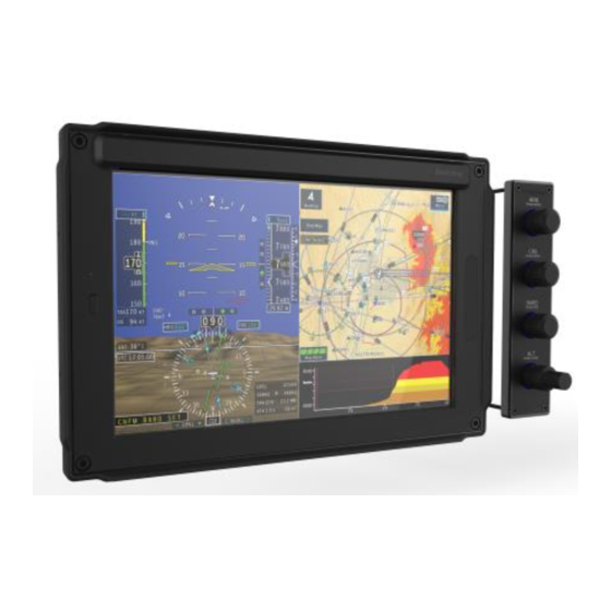
XVUE TOUCH
BENDIXKing XVUE TOUCH Manuals
Manuals and User Guides for BENDIXKing XVUE TOUCH. We have
1
BENDIXKing XVUE TOUCH manual available for free PDF download: Installation Manual
BENDIXKing XVUE TOUCH Installation Manual (280 pages)
PRIMARY FLIGHT DISPLAY SYSTEM
Brand:
BENDIXKing
| Category:
Avionics Display
| Size: 30 MB
Table of Contents
Section 1
7
Table of Contents
7
1 Introduction
19
How to Use this Manual
19
General
19
Observance of Manual Instructions
19
Symbols
19
Units of Measure
19
Electrostatic Discharge
19
Figure 1-1 Symbols
19
References
20
Bendixking/Vendor Publications
20
Other Publications
20
Table 1-1 Bendixking/Vendor References
20
Table 1-2 Standard References
20
Acronyms and Abbreviations
21
Table 1-3 Acronyms and Abbreviations
21
Terminology
26
2 General Information
27
Introduction
27
Scope
27
Table 2-1 Xvue Touch System Components
27
Xvue Touch Overview
28
Figure 2-1 Xvue Touch System Components
28
KSD 100EXP Primary Flight Display
29
KCP 100EXP Control Panel
29
Figure 2-2 Xvue Touch System Block Diagram
29
KG 71EXP Air Data Attitude Heading Reference System (ADAHRS)
30
KMG 7010/MD32 Magnetometer
30
KDC 100EXP Data Converter
30
KTP 73 OAT Probe
31
Technical Specifications
31
Table 2-2 KSD 100EXP Primary Flight Display Specifications
31
Table 2-3 KCP 100EXP Control Panel Specifications
31
Table 2-4 KG 71EXP ADAHRS Specifications
32
Table 2-5 KG 71EXP ADAHRS Performance Characteristics
32
Table 2-6 KMG 7010 Magnetometer Specifications
33
Table 2-7 MD32 Magnetometer Specifications
33
Table 2-8 KDC 100EXP Data Converter Specifications
34
Table 2-9 KTP 73 Outside Air Temperature Probe Specifications
34
Environmental Qualification Form (EQF)
35
Table 2-10 KSD 100EXP Environmental Qualification Form (EQF)
35
Table 2-11 KCP 100EXP Environmental Qualification Form (EQF)
37
Table 2-12 KG 71EXP Environmental Qualification Form (EQF)
39
Table 2-13 KMG 7010 Environmental Qualification Form (EQF)
41
Table 2-14 MD32 Environmental Qualification Form (EQF)
43
Table 2-15 KDC 100EXP Environmental Qualification Form (EQF)
44
Table 2-16 KTP 73 Environmental Qualification Form (EQF)
44
Regulatory Compliance
45
Table 2-17 Xvue Touch System Component Regulatory Compliance
45
Databases
46
Navigation Database
46
Cartographic Database
46
Obstacle Database
46
Terrain Database
46
Instrument Procedure Charts Database
46
Low Altitude Database
46
High Altitude Database
46
VFR Sectional Database
46
Synthetic Vision
46
Recommended Standby Instruments
47
Required GPS Navigator
47
Installation Limitations
47
Figure 2-3 Standby Instrument Power Requirements
48
Permission
49
Repair and Return
49
3 Xvue Touch System Installation Overview
50
Figure 3-1 Example Instrument Panel Modification
50
Pre-Installation Checklist
52
Table 3-1 Pre-Installation Checklist
52
Available Equipment
54
Installation Materials
54
Table 3-2 Xvue Touch System Components and Kits
54
Table 3-3 Installation Kit, Backshell Assembly - KSD 100EXP, PN 89000120-002
54
Table 3-4 Installation Kit, Configuration Module & Connectors - KSD 100EXP, PN 89000120-003
55
Table 3-5 Installation Kit, Mounting Hardware and Grip - KSD 100EXP, PN 89000120-007
55
Table 3-6 KCP 100EXP Control Panel Installation Kit for Portrait Mounting, PN 89000126-004
55
Table 3-7 KCP 100EXP Control Panel Installation Kit for Landscape Mounting, PN 89000126-005
55
Table 3-8 KG 71EXP Installation Kit PN 89000123-007
56
Table 3-9 KMG 7010 Installation Kit PN 050-03643-0000
56
Table 3-10 MD32 Connector Kit PN 9019092-1
56
Table 3-11 KDC 100EXP Installation Kit PN 89000138-002
56
Accessories and Support Equipment Available from Bendixking
57
Materials Required but Not Supplied
57
Table 3-12 Xvue Touch System Accessories and Support Equipment
57
Table 3-13 Installation Materials Required but Not Supplied
57
Tools Required but Not Supplied
59
Table 3-14 Tools Required but Not Supplied
59
Unpacking and Inspection
60
System Interfaces
61
Standard Interface Definitions
61
Discrete I/O
61
Discrete Inputs
61
Table 3-15 KSD 100EXP Discrete Input Ground/Open (DIGO) States
61
Table 3-16 KSD 100EXP Discrete Input 5V/Open (DI5VO) States
61
Table 3-17 KSD 100EXP Discrete Input 15V/Open (DI5VO) States
61
Table 3-18 KSD 100EXP Discrete Input 28V/Open (DI28VO) States
61
Discrete Outputs
62
Serial I/O
62
Arinc 429 I/O
62
Arinc 453 I/O
62
Installation Considerations
62
Table 3-19 KSD 100EXP Discrete Output Ground/Open (DOGO) States
62
Table 3-20 KSD 100EXP Discrete Output 5V/Open (DO5VO) States
62
Table 3-21 KSD 100EXP Discrete Output 28V/Open (DO28VO) States
62
Figure 3-2 Xvue Touch System Interfaces
63
Xvue Touch System Interfaces
64
Table 3-22 Xvue Touch Compatible Equipment
64
Instrument Panel
66
Standby Instruments
67
Standby Instrument Location
67
Standby Attitude Indicator
67
Standby Airspeed Indicator
68
Standby Altimeter
68
Required GPS Navigator
68
KSD 100EXP Installation Considerations
68
KSD 100EXP - Field of View Considerations
69
Figure 3-3 KSD 100EXP Primary Field of View
69
KSD 100EXP Cooling Considerations
70
KCP 100EXP Installation Considerations
70
KCP 100EXP Location
70
Figure 3-4 KSD 100EXP Location (Attitude Indicator)
70
KG 71EXP Installation Considerations
71
KG 71EXP Location
71
KG 71EXP Orientation
72
Figure 3-5 Supported KG 71EXP Installation Orientations
72
KG 71EXP Cooling Considerations
73
KMG 7010/MD32 Installation Considerations
73
KMG 7010/MD32 Location
73
KMG 7010/MD32 Orientation
73
Magnetic Interference
74
Ground Checks - Prior to Installation of the Magnetometer
74
Ground Checks - after Magnetometer Installation and Compass Swing
74
KDC 100EXP Installation Considerations
75
KDC 100EXP Location
75
KDC 100EXP Orientation
75
KTP 73 Installation Considerations
75
KTP 73 Location
75
Figure 3-6 Lightning Zones
76
Placards and Labels
77
Power Distribution
77
Circuit Protection
77
Cable and Wiring
77
Shield Termination
78
Electrical Bonding Considerations
78
Figure 3-7 Termination Procedure
78
Pitot-Static Plumbing Considerations
79
External Annunciators
79
External System Interface Considerations
79
Navigation Receiver
79
ADS-B Traffic, FIS-B Weather and Tfrs
79
Autopilot Interface
79
Table 3-23 Supported Receivers
79
Autopilot Attitude Indicators/Gyros
80
Autopilot Turn Coordinators
80
Autopilot Altitude Pre-Selector and Remote Annunciators
80
Audio Panel
80
Part 121/Part 135 Considerations
80
4 Xvue Touch System Installation Procedures
81
Introduction
81
Instrument Panel Preparation Procedure
81
KSD 100EXP Installation
82
KSD 100EXP Connectors/Configuration Module
82
Figure 4-1 KSD 100EXP (Back View)
82
J1 Connector Assembly
83
Figure 4-2 Bendixking Backshell Assembly
83
Figure 4-3 KSD 100EXP J1 Connector Assembly
83
J2 Connector/Configuration Module Assembly
84
Figure 4-4 KSD 100EXP J2 Connector Assembly
84
Figure 4-5 Configuration Module Circuit Card Assembly (Primary Side)
84
Figure 4-6 Configuration Module Inside J2 Backshell
85
Table 4-1 Configuration Module (J2 Backshell) Pin Descriptions
85
Figure 4-7 Wired Configuration Module Circuit Card Assembly
86
Figure 4-8 Bottom Side of J2 Backshell
86
KSD 100EXP Installation Procedures
87
Figure 4-9 KSD 100EXP Grip Installation (Sheet 1 of 2)
87
Figure 4-10 KSD 100EXP Grip Installation (Sheet 2 of 2)
88
KSD 100EXP Installation Unit Verification
89
Figure 4-11 KSD 100EXP Installation
89
KCP 100EXP Installation
90
KCP 100EXP Instrument Panel Installation Procedures
90
Figure 4-12 KCP 100EXP Installation
90
KCP 100EXP Center Stack Installation Procedures
91
KCP 100EXP Post Installation Unit Verification
91
Figure 4-13 KCP 100EXP Landscape Center Stack Installation
91
KG 71EXP Installation
92
KG 71EXP Installation Procedures
92
Figure 4-14 KG 71EXP ADAHRS Installation Diagram
92
KG 71EXP Post Installation Unit Verification
93
Figure 4-15 KG 71EXP Pressure Fitting Identification Diagram
93
KMG 7010 Installation
94
KMG 7010 Installation Procedures
94
Figure 4-16 KMG 7010 Magnetometer
94
Figure 4-17 KMG 7010 Magnetometer Installation Diagram
95
KMG 7010 - Post Installation Unit Verification
96
MD32 Installation
96
MD32 - Post Installation Unit Verification
96
KDC 100EXP Installation
96
Figure 4-18 KDC 100EXP Connector
96
KDC 100EXP Installation Procedures
97
Figure 4-19 KDC 100EXP Data Connector Installation Diagram
98
KDC 100EXP - Post Installation Unit Verification
99
KTP 73 Installation
99
KTP 73 Installation Procedures
99
KTP 73 - Post Installation Unit Verification
100
Xvue Touch System Components and Wiring Location Data
100
Wiring Harness
100
Figure 4-20 KTP 73 Installation Diagram
100
Weight and Balance Analysis
101
Table 4-2 Wiring Harness Equipment
101
Table 4-3 Xvue Touch System Component Weights & Centers of Gravity
101
Aircraft Electrical Load Analysis (ELA)
103
Aircraft with Existing ELA
103
Aircraft Without an Existing ELA - Measurement Method
103
Table 4-4 Typical LRU Current Draw
103
Aircraft Without an Existing ELA - Analysis Method
104
Airplane Flight Procedures (AFP)
104
5 Connector Pinout Information
105
Ksd 100Exp
105
Table 5-1 KSD 100EXP J1 Pin Descriptions (Viewed from LRU)
105
Table 5-2 KSD 100EXP J2 Pin Descriptions (Viewed from LRU)
107
Kcp 100Exp
110
Kg 71Exp
110
KG 71EXP Connector - J71
110
Table 5-3 KCP 100EXP J1 Pin Descriptions (Viewed from LRU)
110
Table 5-4 KG 71EXP J71 Pin Descriptions (Viewed from LRU)
110
KG 71EXP Pressure Ports
112
Figure 5-1 Pressure Port Fitting(S)
112
Table 5-5 Pressure Port Descriptions
112
KG 71EXP Maintenance Port
113
Kmg 7010
113
Table 5-6 KG 71EXP Maintenance Port Pin Descriptions (Viewed from LRU)
113
Table 5-7 KMG 7010 DB-9 Pin Descriptions (Viewed from LRU)
113
Md32
114
Figure 5-2 KMG 7010 Backshell
114
Table 5-8 MD32 DB-9 Pin Descriptions (Viewed from LRU)
114
Kdc 100Exp
115
Figure 5-3 KDC 100EXP Backshell
115
Table 5-9 KDC 100EXP Pin Descriptions (Viewed from LRU)
115
Configuration Module
116
Table 5-10 KTP 73 Wire Descriptions
116
Table 5-11 Configuration Module (J2 Backshell) Pin Descriptions
116
6 System Configuration
117
Figure 6-1 KSD 100EXP Installation/Maintenance Functional Diagram
118
Mounting, Wiring, and Power Checks
119
Figure 6-2 KG 71EXP Installation/Maintenance Functional Diagram
119
KSD 100EXP Configuration (PFD) Setup
120
Figure 6-3 Database Acknowledge Screen
120
Figure 6-4 APM Configuration Mismatch Screen
121
Figure 6-5 Config Mode Screen
121
Figure 6-6 Configuration Preview Window
122
Figure 6-7 Installer Main Menu
123
System Configuration Setup
124
Figure 6-8 System Config Sub-Menu
124
Lighting
125
External Dimming
125
Figure 6-9 Lighting Sub-Menu
125
Figure 6-10 External Dimming Calibration Sub-Menu
125
Figure 6-11 Minimum Brightness Level
126
Figure 6-12 Maximum Brightness Levels
127
Aircraft Tail Number
128
Figure 6-13 A/C Tail # Keypad
128
Figure 6-14 A/C Tail Number
128
Aircraft Serial Number
129
Aircraft Pitch Bias
129
Figure 6-15 A/C Serial # Keypad
129
Figure 6-16 A/C Serial
129
Pilot V-Speed Locking
130
Figure 6-17 Pitch Bias Keypad
130
Engine Configuration
131
Units Configuration
131
Figure 6-19 Pilot V-Spd Locked/Unlocked Toggle
131
Figure 6-20 Engine Configuration
131
Figure 6-21 Units Configuration
131
PFD Configuration Setup
132
Figure 6-22 Message Center Caution for V-Speed Unit Changes
132
Figure 6-23 PFD Sub-Menu
132
Vertical Speed Indicator Range
133
Figure 6-24 Vertical Speed Tape Examples (1/2 PFD View)
133
Airspeed
134
Figure 6-25 VSI Selection Menu
134
Figure 6-26 V-Speed Tape Illustration
135
Figure 6-27 Airspeed Sub-Menu
136
Master Audio Volume
137
Figure 6-28 VNE V-Speed Keypad Example
137
Terrain Awareness and Warning System (TAWS) Toggle
138
Figure 6-29 Master VOL Sub-Menu
138
Figure 6-30 TAWS Toggle
138
KSD Altitude Preselect Toggle
139
GPS/NAV Configuration Setup
139
Figure 6-31 GPS/NAV Sub-Menu
139
Table 6-1 Supported Navigation Sources
140
GPS Navigation Source
141
Figure 6-32 GPS 1 Sub-Menu
141
VLOC Navigation Source
142
Figure 6-33 GPS2 Sub-Menu
142
Figure 6-34 VLOC1 Sub-Menu
143
Figure 6-35 VLOC2 Sub-Menu
144
Autopilot Configuration Setup
145
Figure 6-36 Autopilot Sub-Menu
145
Table 6-2 Supported Autopilots
146
AP Computer
147
Figure 6-37 AP Computer Sub-Menu
147
Sync FD Offset
148
Sync FD Gain
148
GPSS K Factor
148
Figure 6-38 AP Computer
148
Figure 6-39 GPSS K Factor Keypad
149
Broadcast WX Configuration
150
Figure 6-41 Broadcast WX Sub-Menu
150
Table 6-3 Supported Broadcast WX Sources
150
Traffic Configuration Setup
151
Figure 6-42 Broadcast LRU Sub-Menu
151
Table 6-4 Supported ADS-B Traffic Sources
151
Figure 6-43 Traffic Sub-Menu
152
Figure 6-44 ADS-B Sub-Menu
152
Save & Exit Configuration Mode
153
KG 71EXP Configuration (ADAHRS)
153
Figure 6-45 Installer Menu Closed
153
KG 71EXP Maintenance Interface Configuration
154
Figure 6-46 CMT Startup Screen
154
KG 71EXP Orientation
155
Figure 6-47 CMT Main Configuration Screen
155
Figure 6-48 KG 71EXP Orientation Drop-Down List
156
KG 71EXP Digital I/O Configuration
157
Figure 6-49 CMT Confirmation of Orientation and Offsets Store
157
ARINC 429 Transmit Channel Configuration
158
Figure 6-50 CMT Page for Digital I/O Configuration
158
Same as Tx0 (for KSD 100EXP)
159
Attitude & Heading
159
Altitude & Temperature
159
Figure 6-51 KG 71EXP ARINC Transmit Drop-Down List
159
Air Data
160
Attitude Interface
160
Altitude Interface
160
Custom Configuration
160
Table 6-5 KG 71EXP AHRS Output Labels
161
Table 6-6 KG 71EXP Air Data Output Labels
161
Figure 6-52 ARINC Transmit Channel Custom Configuration
162
KG 71EXP Transponder Serial Interface
163
KMG 7010/MD32 Calibration (Magnetometer)
163
Table 6-7 KMG 7010/MD32 Installation Orientation Options
164
Magnetometer Installation Orientation
165
Figure 6-53 KMG 7010 Calibration Page
165
Figure 6-54 X, Y, Z Axis Positive Direction
166
Magnetometer Compensation
167
Figure 6-55 KMG 7010/MD32 Calibration Reading
168
KTP 73 Configuration (Outside Air Temperature Probe)
169
Figure 6-56 Completion of Magnetometer Calibration
169
7 System Checkout
170
Recommended Test Equipment
170
Xvue Touch System Post Installation System Checkout
170
Figure 7-1 KSD 100EXP Screen
170
Figure 7-2 Menu Button
170
Attitude Checkout
171
Heading Checkout
171
Leak Test
171
Altitude Display/Vertical Display and Standby Altimeter Checkout
171
Airspeed Display and Standby Airspeed Indicator Checkout
173
Figure 7-3 PFD Setup Sub-Menu
173
Figure 7-4 Airspeed Labels Button
173
Outside Air Temperature Checkout
174
GPS Receiver
174
Figure 7-5 CDI Source Sub-Menu (Options Shown for Reference)
174
Figure 7-6 Main Menu
175
Figure 7-7 PFD Menu
175
Figure 7-8 Bearing Pointers Sub-Menu
176
Figure 7-9 Pointer 1 Sub-Menu
176
NAV Receiver
177
Figure 7-10 CRS Button (Value Shown for Reference Only)
178
Figure 7-11 SYNC Button (Value Shown for Reference Only)
178
Universal Access Transceiver (UAT) Checkout
180
Autopilot System Setup
181
Autopilot & KSD 100EXP Interface
181
Autopilot & KSD 100EXP Interface Checkout Procedures
181
Figure 7-12 UAT Fail Message
181
KCP 100EXP Checkout
182
Interfaced Subsystem Checkout
182
Navigator
182
Taws/Traffic
182
Lighting Checkout
182
EMI Interaction Checkout
183
Post Installation Flight Checks
183
Post Installation Activities
183
Database Updates
183
USB Database Loading
184
Figure 7-13 System Tools Menu
184
Figure 7-14 Database Loading Tool Button
184
Table 7-1 Test Tolerance from 14 CFR Part 43 Appendix E Table 1
184
Table 7-2 Available Database
184
Figure 7-15 Database Loading Menu
185
Figure 7-16 Database Loading Page (Unpacking)
185
Figure 7-17 Database Loading Page
186
Figure 7-18 Database Install Buttons
186
Figure 7-19 Database Loading in Progress Screen
187
Figure 7-20 Database Loading Complete
187
Wi-Fi Database Loading
188
Wingman Services Databases
188
Figure 7-21 KSD 100 Wi-Fi Connection Enabled
188
Figure 7-22 Connected to KSD Wi-Fi
189
Figure 7-23 Datamanager Lite Main Page
189
Figure 7-24 Wi-Fi Webpage with Selected Database
190
Figure 7-25 Uploading Databases to KSD 100EXP
190
Figure 7-26 Verifying Databases
190
Seattle Avionics Databases
191
Figure 7-27 Wi-Fi Database Loading Complete
191
Figure 7-28 Restart KSD 100EXP Window
191
Figure 7-29 Flyq App Main Screen
192
Figure 7-30 Chartdata Manager Screen
193
Figure 7-31 Flyq Application Detected Window
194
Figure 7-32 Flyq Database Update Available Window
195
Figure 7-33 Performing Flyq Database Update Window
195
Figure 7-34 Performing Flyq Database Update Progress Window
195
Database Loading Errors
196
USB Database Loading Errors
196
Figure 7-35 Database(S) Update Complete Window
196
Table 7-3 USB Database Loading Error Messages
196
Wi-Fi Database Loading Errors
197
Figure 7-36 Database Loading Completed with Errors Window
197
Figure 7-37 Wi-Fi Serial Number Mismatch Example
197
Figure 7-38 Flyq Database Update Error Message
198
Table 7-4 Wi-Fi Database Loading Errors
198
Xvue Touch Flight Software Update
199
KSD 100EXP Software Update
199
Figure 7-39 Flyq Wi-Fi Connection Failed Message
199
KSD 100EXP Software Field Loading Procedure
200
Figure 7-40 Software Loading Sub-Menu (Check for USB Updates)
200
Figure 7-41 Software Loading Sub-Menu (New Software Found)
201
Figure 7-42 Software Loading Pop-Up Window (Initiate)
201
Figure 7-43 Software Loading Pop-Up Window (Loading in Progress)
201
Figure 7-44 Software Loading Pop-Up Window (Loading Complete)
202
Figure 7-45 Software Loading Pop-Up Window (Power Cycle)
202
Figure 7-46 Restore Data to APM
202
KSD 100EXP Software Loading Errors
203
KG 71EXP Software Update
203
Table 7-5 Software Loading Error
203
8 Troubleshooting
204
Table 8-1 Xvue Touch System Troubleshooting Chart
204
Built-In-Test (BIT) Function
207
P-Bit
207
Table 8-2 P-BIT Failures Troubleshooting Chart
207
C-Bit
208
Table 8-3 C-BIT Failures Troubleshooting Chart
209
KSD 100EXP Touch Calibration
210
KSD 100EXP Manual Touch Calibration
210
Figure 8-1 Screen Maint Menu
210
Figure 8-2 Manual Touch Calibration Menu
210
Figure 8-3 Example of Touch Calibration Utility Screen
211
Figure 8-4 Example of the Touch Calibration Utility Test Screen
212
Default Touch Calibration
213
Figure 8-5 Reverting Touch Calibration Screen
213
Figure 8-6 Restore Def. Touch Cal. Screen
213
Figure 8-7 Restoration of Default Values Successful Screen
214
KG 71EXP Troubleshooting
215
Table 8-4 KG 71EXP Installation Troubleshooting
215
Table 8-5 KG 71EXP Event Codes
217
KMG 7010/MD32 Troubleshooting
220
Troubleshooting - Continuous Measurement Disturbances
220
Troubleshooting - Significant Difference between Required and Sensed Heading
220
Alerts
220
Table 8-6 Alerts Troubleshooting Chart
220
Repair and Return
226
9 Instructions for Continued Airworthiness
227
Purpose
227
ICA Content
227
Description of System and Installation
227
Airworthiness Limitations and Scheduled Maintenance
227
Airworthiness Limitations
227
Scheduled Maintenance Checks
227
Control and Operating Information
227
Unscheduled Maintenance
227
Cleaning
227
Screen Cleaning
228
IR Bar Cleaning
228
Inspection
229
Configuration Module Inspection
229
Xvue Touch System Bonding Inspection
229
Inspection Criteria
230
Table 9-1 ICA Inspection Criteria
230
Adjustments
234
Testing
234
Lubrication
234
Servicing Information
234
Troubleshooting
234
Storage Limitation
234
Removal and Reinstallation Information
234
Removal
234
KSD 100EXP Removal
234
KCP 100EXP Removal
235
KTP 73 Removal
235
KG 71EXP Removal
235
KMG 7010 Removal
235
MD32 Removal
235
KDC 100EXP Removal
235
Reinstallation
236
KSD 100EXP Reinstallation
236
KCP 100EXP Reinstallation
236
KTP 73 Reinstallation
236
KG 71EXP Reinstallation
236
KMG 7010 Reinstallation
236
MD32 Reinstallation
236
KDC 100 EXP Reinstallation
236
Return to Service
237
Appendix A Outline and Installation Drawings
238
Figure A-1 KSD 100EXP Center of Gravity
238
Figure A-2 KSD 100EXP Panel Cutout Dimensions
239
Figure A-3 KCP 100EXP Dimensions and Center of Gravity - Portrait Orientation
240
Figure A-4 KCP 100EXP Dimensions and Center of Gravity - Landscape Orientation
241
Figure A-5 KCP 100EXP Panel Cutout Dimensions
242
Figure A-6 KG 71EXP Dimensions and Center of Gravity
243
Figure A-7 KG 71EXP Mounting Hole Pattern Diagram
244
Figure A-8 KMG 7010 Outline and Mounting Drawing (Sheet 1
245
Figure A-9 KMG 7010 Outline and Mounting Drawing
246
Figure A-10 MD32 Outline Drawing
247
Figure A-11 KDC 100EXP Outline and Mounting Drawing (Sheet 1
248
Figure A-12 KDC 100EXP Outline and Mounting Drawing (Sheet 2
249
Figure A-13 KTP 73 Dimensions and Center of Gravity
250
Figure A-14 KTP 73 Mounting Hole Pattern
251
Figure A-15 KTP 73 Generic Doubler (for 0.016 - 0.032 Inch Skin Thickness
251
Appendix B Interconnect Diagrams
252
Figure B-1 Xvue Touch Power Connection Diagrams
252
Figure B-2 Autopilot Interconnect Diagram
253
Figure B-3 Weather and Traffic Interconnect Diagram
254
Figure B-4 Navigation Interconnect Diagram
255
Figure B-5 Audio Panel Interconnect Diagram
256
Figure B-6 KSD 100EXP LRU Interconnect Diagram
257
Appendix C Xvue Touch System Installation Worksheet
262
Table C-1 Xvue Touch System Component Locations
262
Figure C-1 Xvue Touch System Components and Cable Routing (Top View
263
Figure C-2 Xvue Touch System Components and Cable Routing (Side View
264
Figure C-3 Xvue Touch System Circuit Breakers and Switch Locations
264
Table C-2 Electrical Load Analysis - Normal Operating Conditions
265
Appendix D Md32 Installation Manual
266
Section 2
270
General Description
271
Introduction
271
Technical Specifications
272
Electrical Attributes
272
Physical Attributes
272
Performance Limits
272
Qualifications
272
Installation
273
General Information
273
Parts List
273
Equipment Location
273
Limitations
273
Modifications
274
Cable Harness
275
Wire Gauge Selection
275
Pin Assignment Information
275
Installation Completion
275
Conformance
277
Instructions for Continued Airworthiness
277
Environmental Qualification Statement
278
Advertisement
Advertisement
Related Products
BENDIXKing xVue Touch Experimental
BENDIXKing 700-00179-700
BENDIXKing 700-00179-710
BENDIXKing 700-00182-700
BENDIXKing 700-00182-701
BENDIXKing 700-00182-710
BENDIXKing 700-00182-711
BENDIXKing AeroNav 780
BENDIXKing AeroNav 800
BENDIXKing AeroNav 880
BENDIXKing Categories
GPS
Transceiver
Autopilot System
Avionics Display
Radio
More BENDIXKing Manuals
Login
Sign In
OR
Sign in with Facebook
Sign in with Google
Upload manual
Upload from disk
Upload from URL