Table of Contents
Advertisement
Quick Links
Advertisement
Table of Contents

Subscribe to Our Youtube Channel
Related Manuals for BENDIXKing KI 300


Summary of Contents for BENDIXKing KI 300
- Page 1 KI 300/KA 310 PILOT’S GUIDE...
- Page 2 International: 1-602-365-7027 Website: www.bendixking.com/support Email: techsupport@bendixking.com Copyright - Notice Copyright 2017 BendixKing. All rights reserved BendixKing is a registered trademark of Honeywell International Inc. All other marks are owned by their respective companies. Printed in U.S.A Pub. No. 89000004-201-r000 Revised Oct/2017...
- Page 3 KI 300/KA 310 Pilot’s Guide Legal Notice Honeywell - Confidential THIS COPYRIGHTED WORK AND ALL INFORMATION ARE THE PROPERTY OF HONEYWELL INTERNATIONAL INC., CONTAIN TRADE SECRETS AND MAY NOT, IN WHOLE OR IN PART, BE USED, DUPLICATED, OR DISCLOSED FOR ANY PURPOSE WITHOUT PRIOR WRITTEN PERMISSION OF HONEYWELL INTERNATIONAL INC.
- Page 4 KI 300/KA 310 Pilot’s Guide retains no copies of the Materials and you provide prior written notice to Honeywell. Rights In Materials - Honeywell retains all rights in these Materials and in any copies thereof that are not expressly granted to you, including all rights in patents, copyrights, trademarks, and trade secrets.
- Page 5 KI 300/KA 310 Pilot’s Guide THERE ARE NO OTHER WARRANTIES, WHETHER WRITTEN OR ORAL, EXPRESS, IMPLIED OR STATUTORY, INCLUDING, BUT NOT LIMITED TO, (i) WARRANTIES ARISING FROM COURSE OF PERFORMANCE, DEALING, USAGE, OR TRADE, WHICH ARE HEREBY EXPRESSLY DISCLAIMED, OR...
- Page 6 KI 300/KA 310 Pilot’s Guide Warranty/Liability Advisory WARNING: HONEYWELL ASSUMES NO RESPONSIBILITY FOR ANY HONEYWELL EQUIPMENT WHICH IS NOT MAINTAINED AND/OR REPAIRED IN ACCORDANCE WITH HONEYWELL’S PUBLISHED INSTRUCTIONS AND/OR HONEYWELL’S FAA/SFAR 36 REPAIR AUTHORIZATION. NEITHER DOES HONEYWELL ASSUME RESPONSIBILITY FOR SPECIAL TOOLS AND TEST EQUIPMENT FABRICATED BY COMPANIES OTHER THAN HONEYWELL.
- Page 7 KI 300/KA 310 Pilot’s Guide Record of Revisions Revision Revision Description Date 10/23/17 Initial release Current Revision Description Section Description Initial release 89000004-201 Rev 0 Oct 2017 © Honeywell International Inc. Do not copy without express permission of Honeywell.
- Page 8 KI 300 system. IMPORTANT INFORMATION The KI 300 display has a high-quality optical coating. Clean the display with a clean, lint-free cloth using mild water-based detergent or isopropanol. DO NOT USE CLEANERS THAT CONTAIN AMMONIA.
-
Page 9: Table Of Contents
KI 300/KA 310 Pilot’s Guide TABLE OF CONTENTS 1 System Overview ..................1 Introduction ..........................1 KI 300 Product Description ....................1 KI 300 Functions ....................... 2 System Interfaces ......................4 KA 310 Product Description .................... 5 KA 310 Functions ......................6 System Interfaces ...................... - Page 10 Operational Limitations ....................30 Acronyms and Abbreviations ..............1 LIST OF FIGURES Figure 1 KI 300 Electronic Attitude Indicator .............. 1 Figure 2 KA 310 Autopilot Adapter ................... 5 Figure 3 Power on Screen...................... 9 Figure 4 Heating Message ....................9 Figure 5 Sensor &...
- Page 11 KI 300/KA 310 Pilot’s Guide Figure 24 Aligning Message ....................23 Figure 25 Data Output Fail Caution Message ............24 Figure 26 On Battery Indication & Shutdown Timer ..........25 Figure 27 Charge Status Icon ................... 25 Figure 28 Battery Not Available Indication ..............26 Figure 29 Battery Heating Message ................
- Page 12 KI 300/KA 310 Pilot’s Guide Blank Page Table of Contents 89000004-201 Rev 0 Oct 2017 © Honeywell International Inc. Do not copy without express permission of Honeywell.
-
Page 13: System Overview
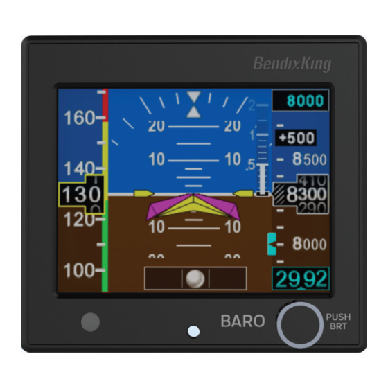
This manual describes the operation of the BendixKing KI 300 Electronic Attitude Indicator and KA 310 Autopilot Adapter. It is intended for use by pilots operating the KI 300/KA 310 in normal and abnormal operating conditions. KI 300 PRODUCT DESCRIPTION The KI 300 Electronic Attitude Indicator is a panel mounted attitude, airspeed, altitude, vertical speed and slip instrument. -
Page 14: Ki 300 Functions
KI 300/KA 310 Pilot’s Guide KI 300 FUNCTIONS The KI 300 performs the following functions: • Display of Indicated Airspeed (Knots or Mph) • Display of Barometric Altitude (Feet) • Display of Roll & Pitch (Fixed Pointer Format, Degrees) •... - Page 15 KI 300/KA 310 Pilot’s Guide • Configuration of Baro Default Value • Configuration of Battery Type • Enable/Disable Airspeed Tape • Enable/Disable Altitude Tape • IVSI Enable/Disable and Filter Lag • Slip/Skid indicator (Ball, polygon, both) • Configuration of Autopilot Interface (None, Analog, Analog w/FD, Digital) •...
-
Page 16: System Interfaces
Altitude is barometrically corrected by the pilot entered baro value prior to being displayed. Aircraft power is the only electrical interface present for the KI 300. Communication to the KA 310 is the only data interface provided from the KI 300. No data interface is provided to other avionic systems in the aircraft. -
Page 17: Ka 310 Product Description
KA 310 PRODUCT DESCRIPTION The KA 310 Autopilot Adapter is an optional remote mounted analog and digital unit. The unit receives attitude data from the KI 300 and converts the serial data into analog or digital outputs to support an interface to BendixKing legacy autopilots. -
Page 18: Ka 310 Functions
KI 300/KA 310 Pilot’s Guide KA 310 FUNCTIONS The KA 310 performs the following functions: • Converts data from the KI 300 into analog attitude outputs. • Converts data from the KI 300 into digital attitude outputs. • Analog Flight Director inputs converted to an output to the KI 300. -
Page 19: System Interfaces
AUTOPILOT INTERFACES When installed with the KI 300, the KA 310 is capable of providing attitude data for the following existing autopilot computers and also able to replace the KRG 331 yaw rate gyro. - Page 20 KI 300/KA 310 Pilot’s Guide Blank Page System Overview 89000004-201 Rev 0 Oct 2017 © Honeywell International Inc. Do not copy without express permission of Honeywell.
-
Page 21: Normal Operation
KI 300/KA 310 Pilot’s Guide 2 Normal Operation INITIAL POWER ON Upon initial power-on, the unit will display the company logo, battery status and software version. If the battery is not installed, has failed self-test, or is in a low-temperature state, the battery life will show... -
Page 22: Alignment
KI 300/KA 310 Pilot’s Guide Figure 5 Sensor & Battery Stabilization ALIGNMENT On power-up, the unit will perform an initial alignment. The aircraft should not be subjected to taxing or excessive motions during this process. Alignment is not normally performed during flight. -
Page 23: Pilot Display And Controls
Figure 7 Pilot Display & Controls The Rotary Knob with pushbutton provides the pilot access to all of the interactive functions of the KI 300. Figure 8 depicts the pushbutton selection of various functions and Table 1 describes the role of the Rotary Knob in each function. -
Page 24: Indicated Airspeed
KI 300/KA 310 Pilot’s Guide Idle Short Press (tap) Medium Press (3s) Long Press (5s) Brightness Altitude Bug On Power Off Short Press Long Press Short Press Long Press Short Press Align Accept Altitude Bug Set Altitude Bug Off Abort... -
Page 25: Indicated Airspeed Limits
KI 300/KA 310 Pilot’s Guide INDICATED AIRSPEED LIMITS Airspeed limits are indicated by means of colored bands and radial lines as follows: Figure 9 IAS Limits The V and V are applicable to multi-engine aircraft only and will not be shown in single engine installations. -
Page 26: Barometric Altitude
KI 300/KA 310 Pilot’s Guide The Under-Speed band and surround coloring is only shown if the aircraft has previously exceeded V . Under-Speed indication is disabled prior to take-off. Airspeed limits can only be configured by an approved mechanic and are not pilot adjustable. -
Page 27: Instantaneous Vertical Speed Indication (Ivsi)
The bar will not appear until the vertical rate exceeds ±100 ft/min. A digital value is also presented to the pilot. The IVSI in the KI 300 uses both the rate of altitude change and the internal accelerometer to provide vertical speed with very little delay. -
Page 28: Altitude Bug
The Altitude Bug is enabled, disabled and adjusted using the Rotary Knob with Pushbutton. The altitude bug is for reference only and is not an altitude pre-select for the autopilot. NOTE: The altitude bug is for reference only. The KI 300 does not support altitude pre-select for the autopilot. -
Page 29: Roll & Pitch
(white ball in a glass tube) or displayed as a polygon at the top of the display. The KI 300 can also be configured to display both slip indicators. The left and right stops represent ± 7 degrees. If the internal slip sensor fails, the area with the ball will be Red-X’ed and/or the polygon will be shaded red. -
Page 30: Decision Height
Figure 15 Decision Height Indicator FLIGHT DIRECTOR COMMAND BARS When the KI 300 and KA 310 are connected to a compatible Flight Control System, the Flight Director Command Bars can be displayed. The Flight Control System enables the Command Bars. -
Page 31: Brightness Adjustment
KI 300/KA 310 Pilot’s Guide BRIGHTNESS ADJUSTMENT The screens brightness is either manually or automatically controlled. By default after power on, the automatic mode is selected. In the automatic mode, the brightness will be adjusted based on the ambient light detected by the bezel mounted light sensor. -
Page 32: Abnormal Operation
KI 300/KA 310 Pilot’s Guide 3 Abnormal Operation Cross Check Memory Error Aligning Autopilot Battery Status Figure 18 Abnormal Operation Indicators Abnormal operating modes and conditions are annunciated by a variety of on-screen indications, as shown in Figure 18 – Abnormal Operation Indicators. -
Page 33: Memory Error
AUTOPILOT OUTPUT FAIL ANNUNCIATION When the KI 300 and KA 310 are connected to a legacy autopilot, it provides analog pitch and roll information to the autopilot. The KI 300 and KA 310 monitor the data interface between the two units. -
Page 34: Data Output Fail Annunciation
KI 300/KA 310 Pilot’s Guide DATA OUTPUT FAIL ANNUNCIATION When the KI 300 and KA 310 are connected to a digital autopilot it provides digital attitude information to the autopilot. The KI 300 and KA 310 monitor the data interface between the two units. If an error is detected, the DATA OUTPUT FAIL / DISCONNECT AP annunciation will flash between the two messages. -
Page 35: Attitude Re-Alignment
KI 300/KA 310 Pilot’s Guide When operating in the Degraded Mode, an amber CROSS CHECK message may be displayed on the screen. Figure 23 Cross Check Message Cross Check may occur during extended periods of maneuvering. Reestablishing straight and level flight allows the unit to reacquire TSO criteria performance. -
Page 36: Transition To And From Battery
KI 300/KA 310 Pilot’s Guide OUTPUT FAIL caution annunciation will be displayed. annunciation is removed when the error is corrected. Figure 25 Data Output Fail Caution Message The DATA OUTPUT FAIL annunciation, may be displayed on initial power up if the KA 310 has not been turned on. The annunciation will disappear when the KA 310 is powered on. -
Page 37: Battery Status
Charge levels above 80% are shown in green and will only be displayed when the KI 300 is operating on battery, between 25% and 80% is shown in amber, and levels below 25% are shown in red. The charge is also shown numerically in percent. -
Page 38: Battery Duration
KI 300/KA 310 Pilot’s Guide If the battery is charging, a charge indicator will be shown over the colored icon as a small white lightning bolt. There is a power-on delay of several minutes prior to the charger being internally enabled. -
Page 39: Cold Temperature Startup
KI 300/KA 310 Pilot’s Guide temperature and a reduced display brightness will be approximately 2 hours. Note that the charge level indicated is an approximation of the remaining capacity of the battery, and will dynamically adjust based on operating environment and conditions. For example, diming of the display will extend the battery duration, this will result in an increase in the percent charge shown. -
Page 40: Flight Director
KI 300/KA 310 Pilot’s Guide FLIGHT DIRECTOR If the flight director data from the KA 310 is lost or becomes invalid the flight director command bars will be removed from the display. DECISION HEIGHT If the decision height data from the KA 310 is lost or becomes invalid the decision height alert will not be displayed. - Page 41 KI 300/KA 310 Pilot’s Guide Blank Page 89000004-201 Abnormal Operation Rev 0 Oct 2017 © Honeywell International Inc. Do not copy without express permission of Honeywell.
-
Page 42: Operational Limitations
KI 300/KA 310 Pilot’s Guide 4 Operational Limitations OPERATIONAL LIMITATIONS The following operational limitations apply: • Geographic limitation: None • Magnetic field sensitivity: None • Lightning direct effects sensitivity: None • Lightning indirect effects sensitivity: Approved for catastrophic functions •... - Page 43 KI 300/KA 310 Pilot’s Guide • No operational capability on internal battery is possible if the battery is faulted, as shown by a Red-X over the battery icon. • Battery charging is disabled below approximately 0°C and above 40°C, or when power input is below approximately 11 VDC.
- Page 44 KI 300/KA 310 Pilot’s Guide Blank Page Operational Limitations 89000004-201 Rev 0 Oct 2017 © Honeywell International Inc. Do not copy without express permission of Honeywell.
-
Page 45: Acronyms And Abbreviations
KI 300/KA 310 Pilot’s Guide Acronyms and Abbreviations Acronyms and abbreviations used in this guide are defined as follows: TERM DEFINITION Percentage Autopilot Battery Degrees Celsius °C Decision Height Federal Aviation Administration Flight Director ft/min feet per minute Gravitational acceleration... - Page 46 KI 300/KA 310 Pilot’s Guide Blank Page Acronyms and Abbreviations 89000004-201 Abbrev-2 Rev 0 Oct 2017 © Honeywell International Inc. Do not copy without express permission of Honeywell.
- Page 48 9201-B San Mateo Blvd. N.E. Albuquerque, NM 87113 U.S.A and Canada: 1-855-250-7027 International: 1-602-365-7027 www.bendixking.com © Honeywell International Inc. Do not copy without express permission of Honeywell.
Need help?
Do you have a question about the KI 300 and is the answer not in the manual?
Questions and answers