Table of Contents
Advertisement
Quick Links
Advertisement
Table of Contents
Troubleshooting

Related Manuals for YOKOGAWA WT500


Summary of Contents for YOKOGAWA WT500
- Page 1 Power Analyzer IM 760201-01E 1st Edition...
-
Page 2: Product Registration
Product Registration Thank you for purchasing YOKOGAWA products. YOKOGAWA provides registered users with a variety of information and services. Please allow us to serve you best by completing the product registration form accessible from our homepage. http://www.yokogawa.com/tm/ PIM 103-02E... - Page 3 Thank you for purchasing the WT500 Power Analyzer. The WT500 is an instrument capable of measuring parameters such as voltage, current, and power with high precision. This user’s manual explains the features, operating procedures, and handling precautions of the WT500. To ensure correct use, please read this manual thoroughly before beginning operation.
-
Page 4: Checking The Package Contents
After receiving the product and opening the package, check the items described below. If the wrong items have been delivered, if items are missing, or if there is a problem with the appearance of the items, contact your nearest YOKOGAWA dealer. WT500 Check that the model name and suffix code given on the name plate on the side panel are the same as those on your order. -
Page 5: Standard Accessories
Communication Interface IM760201-17E CD-ROM User’s Manual (CD-ROM part number: B9319ZZ) (Printed manuals can be purchased separately. Contact your nearest YOKOGAWA dealer.) Power cord (One of the following power cords is included according to the suffix code) Current input protective cover A1006WD... - Page 6 Measurement lead 366925 42 V or less. Length: 2 m. External sensor cable B9284LK For connecting the current sensor input connector of the WT500. Length: 0.5 m. Conversion adapter 758924 BNC-4 mm socket adapter. Rated voltage: 500 V. Measurement lead...
-
Page 7: Safety Precautions
The general safety precautions described herein must be observed during all phases of operation. If the instrument is used in a manner not specified in this manual, the protection provided by the instrument may be impaired. Yokogawa Electric Corporation assumes no liability for the customer’s failure to comply with these requirements. - Page 8 Failure to comply with the precautions below could lead to injury or death. WARNING Use the Correct Power Supply Make sure that the power supply voltage matches the WT500 rated supply voltage and that it does not exceed the maximum voltage range specified for the power cord.
-
Page 9: Waste Electrical And Electronic Equipment
With reference to the equipment types in the WEEE directive Annex 1, this product is classified as a “Monitoring and Control instrumentation” product. Do not dispose in domestic household waste. When disposing products in the EU, contact your local Yokogawa Europe B. V. office. IM 760201-01E... -
Page 10: Conventions Used In This Manual
Conventions Used in This Manual Notes and Cautions The notes and cautions in this manual are categorized using the following symbols. Improper handling or use can lead to injury to the user or damage to the instrument. This symbol appears on the instrument to indicate that the user must refer to the user’s manual for special instructions. -
Page 11: Workflow
Workflow The figure below is provided to familiarize the first-time user with the workflow of WT500 operation. For a description of an item, see the relevant section or chapter. In addition to the sections and chapters that are referenced in the figure below, this manual also contains safety precautions for handling the instrument and performing wiring work. -
Page 12: Table Of Contents
Contents Checking the Package Contents....................... ii Safety Precautions ..........................v Waste Electrical and Electronic Equipment ..................vii Conventions Used in This Manual ....................viii Workflow ............................ix Chapter 1 Component Names and Functions Front Panel, Rear Panel, and Top Panel ................1-1 Setup Menu Display and Operation Keys ................ - Page 13 Contents Setting the Measurement Ranges for an External Current Sensor (Optional) ....4-13 Setting the Scaling Feature When Using a VT or CT ............. 4-16 Setting the Measurement Period ..................4-19 Selecting an Input Filter ....................4-22 Selecting the Data Update Rate ..................4-24 4.10 Selecting an Averaging Method ..................
- Page 14 Connecting to a Network ....................11-2 11.3 Configuring TCP/IP Settings ....................11-3 11.4 Accessing the WT500 from a PC or Workstation (FTP server feature) ......11-12 11.5 Checking the MAC Address and Whether the WT500 Is Equipped with the Ethernet Interface Option ....................11-15 Chapter 12 RGB Video Signal (VGA) Output (Optional) and Other Features 12.1...
- Page 15 Contents 13.4 Displaying the System Overview ..................13-9 13.5 Recommended Part Replacement ................13-10 Chapter 14 Specifications 14.1 Input ..........................14-1 14.2 Display ..........................14-2 14.3 Normal Measurement Functions (Measured Items) ............14-3 14.4 Harmonic Measurement Functions (Measured Items) ........... 14-5 14.5 Accuracy .........................
-
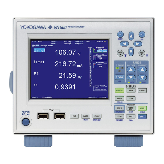
Page 16: Front Panel
Returns the item or value selected with the cursor to its default value. PAGE key Because not all measured items can be displayed on the screen at the same time, the WT500 uses pages to display measured values. You can switch between pages using PAGE and PAGE RESET (see section 5.1) -
Page 17: Front Panel, Rear Panel, And Top Panel
1.1 Front Panel, Rear Panel, and Top Panel Top Panel Vent holes (see section 3.2 for details) Handle There are inlet holes on the bottom panel. IM 760201-01E... -
Page 18: Setup Menu Display And Operation Keys
SHIFT+SET (CAL) Key Combination Use this key combination to execute zero-level compensation. When zero level compensation is executed, the WT500 creates a zero input condition in its internal circuitry and sets the level at that point to the zero level. - Page 19 1.2 Setup Menu Display and Operation Keys Keys for Setting the Measurement Range RANGE ELEMENT ELEMENT VOLTAGE CURRENT • Use this key to select the input element that you want to set the measurement range for. The selected input element will change each time you press ELEMENT. •...
- Page 20 1.2 Setup Menu Display and Operation Keys • Integration (See sections 5.6 to 5.12) Select this item to display a menu for setting the integration mode, integration auto calibration, the integration timer, the reservation time, the watt hour integration method for each polarity, and the ampere hour integration mode.
- Page 21 1.2 Setup Menu Display and Operation Keys Keys for Displaying Measured/Computed Results DISPLAY NUMERIC (See sections 3.16, 5.1, and 6.2) NUMERIC WAVE OTHERS Use this key to display numeric data. • Each time you press NUMERIC, the number of displayed items switches in this order: FORM ITEM 4 Items >...
-
Page 22: And Pressing A Panel Keys Produces The Effect Indicated By The Purple Letters Below It
Holding down SHIFT for 2 seconds or more will lock the WT500 into the shifted state. Pressing SHIFT again will release the shifted state (and the SHIFT key will no longer be illuminated). -
Page 23: Screen Display
Screen Display Display Example When Measuring Power (Numeric display) in Normal Measurement Mode For a description of the screens in other display modes, see the chapters that cover those modes. Indication of on/off status of various features Measurement mode (see section 7.2) •... -
Page 24: Chapter 2 Features
Chapter 2 Features System Configuration and Block Diagram System Configuration Object Being Measured Current sensor (optional) Voltage Current (Apply one or the other) (Apply one of them) ELEMENT VOLTAGE ± CURRENT ± Input element RESET PAGE PAGE RANGE ELEMENT VOLTAGE CURRENT ELEMENT AUTO... -
Page 25: Block Diagram
2.1 System Configuration and Block Diagram Block Diagram Input elements 2 and 3 Input element 1 Voltage input circuit L.P.F. Voltage Input 5.5 kHz ± Zero-crossing L.P.F. USB port detector 500 Hz (for peripherals) Peak detector USB port (PC) Current input circuit GP-IB (optional) L.P.F. -
Page 26: Measurement Functions And Periods
“Measurement Period” on page 2-9. 1 The WT500 samples the instantaneous values of the voltage and current signals at the specified sample rate. The sampled data is processed as numeric data or data used to display waveforms on the screen (waveform display data). - Page 27 1 to 3. An element number is appended to the measurement function symbol for the measured data that the WT500 displays, so that you can tell which data belongs to which element. For example, “Urms1” corresponds to the true rms voltage of element 1.
- Page 28 2.2 Measurement Functions and Periods Wiring Unit The wiring unit is a set of two or three input elements of the same wiring system that are grouped to measure three-phase power. The wiring unit is represented by Σ. The measurement function of a wiring unit is called a Σ function. For example, “UrmsΣ”...
- Page 29 2.2 Measurement Functions and Periods Types of Measurement Functions Used in Harmonic Measurement (Optional) The data of harmonic measurement functions (numeric data) is measured or computed from the sampled data that is described later in “Measurement Period.” * For information about sampled data, see the explanation under “Types of Measurement Functions Used in Normal Measurement,”...
- Page 30 2.2 Measurement Functions and Periods • Harmonic Measurement Functions That Express the Voltage and Current Phase Differences (f) between and within Input Elements There are five kinds of harmonic measurement functions that express phase differences: fUi-Uj, fUi-Uk, fUi-Ii, fUi-Ij, fUi-Ik (i, j, and k are input element numbers) The following explanation of the five kinds of harmonic measurement functions is for the case when the number of input elements in wiring unit Σ...
- Page 31 Element refers to a set of input terminals that can receive a single phase of voltage and current to be measured. The WT500 can contain up to three elements, numbered from 1 to 3. The element number follows the function symbols discussed in “Input Element Harmonic Measurement Functions”...
- Page 32 U-pk, I+pk, I-pk, CfU, and CfI) is also the entire span of the data update interval. • The WT500 determines whether to define the measurement period using the rising or falling edge automatically by choosing the method that will result in the longest measurement period.
-
Page 33: Measurement Conditions
Σ. For example, there are four wiring system patterns on a WT500 that has three input elements installed. • The input element assignment to wiring unit Σ and how Σ functions (such as voltage, current, active power, apparent power, reactive power, power factor, and phase difference) are determined are based on the wiring system pattern. - Page 34 2.3 Measurement Conditions Measurement Range (See section 4.4 for operating instructions) Set the measurement range using an rms value. When directly applying voltage or current signals to an input element, two types of measurement ranges are available: fixed range and auto range. When waveforms are displayed and the crest factor (see section 4.6 for details) is set to 3, the vertical display range corresponds to 3 times the measurement range.
- Page 35 2.3 Measurement Conditions Scaling (See sections 4.5 and 4.6 for operating instructions) When applying current signals through an external current sensor or applying voltage or current signals through an external VT (voltage transformer) or CT (current transformer), the conversion ratio or coefficient can be specified. When Applying Current Signals through an External Current Sensor The output of current sensors that output voltage, such as shunts and clamps, can be applied to the current sensor connector (EXT) and measured.
- Page 36 2.3 Measurement Conditions Input Filter (See section 4.8 for operating instructions) There are two types of input filters. The WT500 makes measurements by synchronizing to the input signal. Therefore, the frequency of the input signal must be measured accurately. Line Filter...
- Page 37 2.3 Measurement Conditions Averaging (See section 4.10 for operating instructions) The averaging function is effective when reading of the numeric display is difficult due to fluctuations. This occurs when the fluctuation of the power supply or the load is large or when the input signal frequency is low.
- Page 38 Peak value Rms value Input signal waveform The crest factor on the WT500 is determined by the ratio of the maximum peak value that can be applied for rated input to the measurement range. Peak value that can be input...
-
Page 39: Power Measurement
Power Measurement When the screen is set to numeric display, measured data such as voltage, current, and power can be displayed. Display Resolution The display resolution for voltage, current, active power, apparent power, reactive power, and so on is 60000. When the range rating (rated value of the specified measurement range) is specified, the Σ... - Page 40 2.4 Power Measurement Changing the Displayed Items You can select a displayed item to change the numeric data that is displayed at that item’ s position. Change the measurement function of the third item Change the element of the third item Scrolling through Pages The numeric display consists of up to nine pages.
- Page 41 2.4 Power Measurement Numeric Display during Harmonic Measurement (See section 6.1 for operating instructions) In addition to the 4, 8, 16, matrix, and All displays, list displays (the single list and double list displays) are also available. Selecting the Number of Displayed Items Just as in ordinary measurement, the number of items can be selected from 4, 8, 16, Matrix, and All Items.
-
Page 42: Computation
Because the equations for deriving the power for distorted waveforms are not defined, none of the equations can be said to be more correct than the other. Therefore, the WT500 provides three equations for determining the apparent power and reactive power. - Page 43 2.5 Computation Type 2 The apparent power of each phase is determined from equation 3, and the results are added to derive the three-phase apparent power. The three-phase reactive power is calculated from the three-phase apparent power and the three-phase active power using equation 4.
- Page 44 2.5 Computation Delta Computation (Optional; See section 5.17 for operating instructions) The sum or difference of the instantaneous voltage or current values (sampled data) between the elements in a wiring unit can be used to determine various types of data such as the differential voltage and phase voltage. This operation is called delta computation.
-
Page 45: Integration
Integration The WT500 can integrate the active power (watt hour), the current (ampere hour), the apparent power (volt-ampere hour), and the reactive power (var hour) values. During integration, the measured and computed values of normal measurements can be displayed in addition to the watt hour, ampere hour, volt-ampere hour, var hour, and integration time values. - Page 46 2.6 Integration Integration Mode (See sections 5.6 and 5.7 for operating instructions) The integration feature has five modes: manual integration mode, normal integration mode, continuous integration mode, real-time integration mode, and real-time continuous integration mode. Manual Integration Mode Integration continues from when you start it until you stop it. However, when the integration time reaches its maximum (10000 hours) or the integrated value reaches its maximum or minimum displayable value (see section 5.6 for details), integration is stopped, and the integration time and integrated value at that point are held.
- Page 47 2.6 Integration Continuous Integration Mode Integration continues for a specified amount of time, and then resets and starts again. Integration repeats until you press STOP. If the integrated value reaches its maximum or minimum displayable value before the specified amount of time has elapsed, integration is stopped, and the integration time and integrated value at that point are held.
- Page 48 2.6 Integration Real-Time Continuous Integration Mode (Continuous integration) You specify the dates and times when integration will start and end, and integration repeats within the start and end times at the interval specified by the timer. When the amount of time specified by the timer elapses, integration resets and starts again. When the specified stop time is reached, or when the integrated value reaches its maximum or minimum displayable value, integration is stopped, and the integration time and integrated value at that point are held.
-
Page 49: Waveform Display
Waveform Display The WT500 displays waveforms based on the data sampled within the data update rate. Selecting the Waveform to Display (See section 3.7 for operating instructions) You can select whether to show or hide the voltage and current waveforms of each input element. - Page 50 This example assumes that a 2-Hz sine wave is measured at a data update rate of 1 s. To display this waveform on the WT500 screen, the number of data points is converted from approximately 100000 to 1002 (501 pairs of maximum and minimum values). Thus, two points (a pair) of waveform display data are derived from approximately 200 points of waveform sampling data.
- Page 51 • Sampling of waveform display data The WT500 samples waveform display data and stores it to memory at a rate of approximately 100 kS/s. The WT500 can accurately display the waveforms of signals with frequencies up to approximately 5 kHz.
- Page 52 2.7 Waveform Display Trigger (See section 7.5 for operating instructions) A trigger is said to have “occurred” when the specified trigger condition is met and a waveform is displayed on the screen. Trigger Mode The trigger mode specifies the conditions for updating the display. •...
- Page 53 2.7 Waveform Display Vertical Waveform Zoom (See section 7.6 for operating instructions) Each displayed waveform can be scaled vertically by a zoom factor of 0.1 to 100. The waveform is scaled around the zero-input line. When the zoom factor is doubled 300 Vpk 300 Vpk 150 Vpk...
- Page 54 2.7 Waveform Display Split Waveform Display and Assignment (See section 7.7 for operating instructions) The screen can be divided into windows, and waveforms can be assigned to those windows. The screen can be divided into up to four windows. This function is useful when there are many waveforms and it is difficult to view them all in a single display.
- Page 55 2.7 Waveform Display Waveform Label Display (See section 7.8 for operating instructions) You can turn the display of waveform labels on or off. Maximum values Waveform labels Minimum values Time at the right end of the screen Time at the left end of the screen Cursor Measurement (See sections 7.9 and 8.10 for operating instructions) The value at the crossing point of the waveform and cursor can be measured and displayed.
-
Page 56: Trend, Bar Graph, And Vector Displays
Scale Settings (See section 8.5 for operating instructions) The WT500 can automatically set the values at the top and bottom of the screen based on the maximum and minimum values of the trend display data (this is referred to as auto scaling). - Page 57 2.8 Trend, Bar Graph, and Vector Displays Bar Graph Display of Harmonic Data (See section 6.7 for operating instructions) On models with the harmonic measurement option, you can display harmonics using bar graphs. The harmonic orders are lined up on the horizontal axis, and the vertical axis represents the amplitude of each harmonic.
- Page 58 U3(1) are at the origin O, the phase relationship can be observed U1(1) in the same fashion as the 3P4W system. U1-U3 U3-U1 (The WT500 does not provide a U1(1) U1-U2 1(1), function for moving the vectors.) U1-I1 U3(1) U1-I2...
-
Page 59: Saving And Loading Data, And Other Miscellaneous Functions
Miscellaneous Functions Storage (See chapter 9 for operating instructions) Numeric data can be stored to the WT500 internal memory or USB memory. The data is stored at the data update rate or at a specified time interval. Saving and Loading from the Storage Medium (See chapter 10 for operating instructions) The WT500 has USB ports (for peripheral devices). - Page 60 2.9 Saving and Loading Data, and Other Miscellaneous Functions Ethernet Interface (Optional) (See chapter 11 for operating instructions) Using the FTP server function, you can access the WT500 from an FTP client on the network and retrieve files from the WT500 internal memory or USB storage.
- Page 61 You can view information about the WT500, such as the model, firmware version (ROM version), input element configuration, and installed options. Self-Test Feature (See section 13.3 for operating instructions) The WT500 can evaluate its internal memory (RAM) and panel keys to determine if they are working properly. 2-38...
-
Page 62: Handling Precautions
Do not remove the case from the instrument. Some parts of the instrument use high voltages and are extremely dangerous. For internal inspection and adjustment, contact your nearest YOKOGAWA dealer. Unplug If Abnormal Behavior Occurs If you notice smoke or unusual odors coming from the instrument, immediately turn off the power and unplug the power cord. - Page 63 3.1 Handling Precautions General Handling Precautions Do Not Place Objects on Top of the Instrument Never stack the instrument or place other instruments or any objects containing water on top of it. Doing so may damage the instrument. Keep Electrically Charged Objects Away from the Instrument Keep electrically charged objects away from the input terminals.
-
Page 64: Installing The Instrument
Installing the Instrument Installation Conditions Install the instrument in an indoors environment that meets the following conditions. Flat, Even Surface Install the instrument on a surface that is flat and even in all directions. If you install the instrument on an uneven or tilted surface, the accuracy of its measurements may be impeded. - Page 65 3.2 Installing the Instrument Installation Position Desktop Place the instrument on a flat, even surface as shown in the figure below. If the instrument is installed in a horizontal position, rubber stoppers can be attached to the feet to prevent the instrument from sliding. One set of rubber feet (two feet) are included in the package.
-
Page 66: Connecting The Power Supply
• Confirm that the power switch is off before connecting the power cord. • To prevent fire and electric shock, use the power cord supplied by YOKOGAWA. • To prevent electric shock, make sure to ground the instrument. Insert the instrument’s power cord into a grounded three-prong outlet. -
Page 67: Turning The Power Switch On And Off
After checking the above, try turning on the power switch while holding down ESC to reset the settings to their initial values (the factory default). For information about the initial settings, see section 3.13, “Initialization.” If the instrument still does not work properly, contact your nearest YOKOGAWA dealer for repairs. IM 760201-01E... - Page 68 (see section 13.2 for details). If this message appears frequently, the battery should be replaced quickly. Do not try to replace the battery yourself. Contact your nearest YOKOGAWA dealer to have the battery replaced. For information about the battery life, see section 13.5.
-
Page 69: Precautions For Wiring The Circuit That You Will Measure
Precautions for Wiring the Circuit That You Will Measure To avoid electric shock and damage to the instrument, follow the precautions below. WARNING • Ground the instrument before connecting measurement cables. The power cord that comes with the instrument is a three-prong cord. Insert the power cord into a grounded three-prong outlet. - Page 70 3.5 Precautions for Wiring the Circuit That You Will Measure • To make the protective measures effective, before applying the voltage or current from the circuit under measurement, check that: • The power cord provided with the instrument is being used to connect to the power supply and that the instrument is grounded.
-
Page 71: Assembling The Adapter For The Voltage Input Terminal
Terminal Assembling the 758931 Safety Terminal Adapter When connecting a measurement cable to a WT500 voltage input terminal, use the 758931 Safety Terminal Adapter that comes with the package or the 758923 Safety Terminal Adapter that is sold separately. When using the 758931 Safety Terminal Adapter, assemble it according to the following procedure. - Page 72 3.6 Assembling the Adapter for the Voltage Input Terminal Explanation Wire the adapters that come with the WT500 or the adapters and various sensors that are sold separately as shown below: Wiring to the Voltage Input Terminal Voltage under measurement...
-
Page 73: Wiring For Accurate Measurements
Wiring for Accurate Measurements To make accurate measurements, refer to the items below when wiring the voltage input and current input terminals. Effects of Stray Capacitance When measuring a single-phase device, the effects of stray capacitance on measurement accuracy can be minimized by connecting the instrument’s current input terminal to the side that is closest to the earth potential of the power source (SOURCE). -
Page 74: Guide For Selecting The Method Used To Measure The Power
For example, if you replace the WT2000 (used in a three-phase, three-wire system) with the WT500 and leave the wiring unchanged, the measured power of each element will be different between the WT2000 and the WT500. Refer to this manual and re-wire the system correctly. -
Page 75: Wiring The Circuit That You Will Measure For Direct Input
Wiring the Circuit That You Will Measure for Direct Input This section explains how to wire the measurement cable directly from the circuit that you will measure to the voltage or current input terminal. To avoid electric shock and damage to the instrument, follow the precautions given in section 3.5, “Precautions for Wiring the Circuit That You Will Measure.”... - Page 76 3.9 Wiring the Circuit That You Will Measure for Direct Input The assignment of elements to the input terminals in the wiring example figures below varies depending on the number of installed input elements. For details, see “Number of Installed Input Elements and Wiring Systems” in section 2.3, “Measurement Conditions.” Note •...
- Page 77 3.9 Wiring the Circuit That You Will Measure for Direct Input Three-Phase, Three-Wire System Wiring Example (Applicable for models 760202 and 760203) If three input elements are available, two three-phase, three-wire systems can be set up (elements 1 and 2, or elements 2 and 3). ±...
-
Page 78: Wiring The Circuit That You Will Measure With A Current Sensor
Number of Installed Input Elements and Wiring Systems The selectable wiring systems vary depending on the number of input elements that are installed in the WT500. For details, see “Number of Installed Input Elements and Wiring Systems” in section 2.3, “Measurement Conditions.”... - Page 79 Space between the connection wires Shunt resistor External sensor cable OUT H (B9284LK, sold separately) WT500 ± Shielded wire OUT L • Connect a shunt resistor to the power earth ground as shown in the figure below. If you have to connect the sensor to the non-earth side, use a wire that is thicker than AWG18 (conductive cross-sectional area of approx.
- Page 80 3.10 Wiring the Circuit That You Will Measure with a Current Sensor The following wiring examples are for connecting shunt resistors. When connecting a clamp-type current sensor that outputs voltage, substitute the shunt-type current sensor with the clamp-type. Clamp-type current sensor Shunt resistor that outputs voltage ±...
- Page 81 3.10 Wiring the Circuit That You Will Measure with a Current Sensor Wiring Example of a Three-Phase, Three-Wire System (3P3W) with a Shunt Resistor SOURCE LOAD ± OUT H OUT L ± OUT L OUT H Input terminal 1 Input terminal 2 ±...
-
Page 82: Wiring The Circuit That You Will Measure With A Vt Or Ct
Number of Installed Input Elements and Wiring Systems The selectable wiring systems vary depending on the number of input elements that are installed in the WT500. For details, see “Number of Installed Input Elements and Wiring Systems” in section 2.3, “Measurement Conditions.”... - Page 83 3.11 Wiring the Circuit That You Will Measure with a VT or CT Note • After you have finished wiring, you must select the wiring system. For details, see section 4.2, “Selecting the Wiring System.” • The thick lines on the wiring diagrams are the sections where the current flows. Use wires that are suitable for the current levels.
- Page 84 3.11 Wiring the Circuit That You Will Measure with a VT or CT Wiring Example of a Three-Phase, Three-Wire System (3P3W) with a VT and CT LOAD SOURCE L CT L CT ± ± ± ± Input terminal 1 Input terminal 2 Wiring Example of a Three-Phase, Three-Wire System with a Three-Voltage, Three-Current Method (3P3W;...
-
Page 85: Setting The Date And Time
3.12 Setting the Date and Time Procedure Press MISC to display the Misc Menu. Turning the Date and Time Display On or Off Use the cursor keys to select Date/Time. Press SET to display the Date/Time dialog box. Use the cursor keys to select Display. Press SET to select ON or OFF. - Page 86 The date and time information is backed up with an internal lithium battery when the power is turned off. • The WT500 contains leap year information. The instrument determines the leap year calendar when new settings are confirmed. If you enter 2/29 for the date on a non-leap year, an error message will be displayed.
-
Page 87: Initializing The Settings
Procedure Note Only initialize the WT500 if you are sure that it is okay for all of the settings to return to their initial values. You cannot undo an initialization. We recommend that you save the setup parameters before initializing the WT500 (see section 10.3 for details). -
Page 88: Entering Values And Character Strings
3.14 Entering Values and Character Strings Entering Values When you select a setup parameter with SET, an entry box appears. Then, you can change the value by using the cursor keys. Use the left and right cursor keys to select digits, and use the up and down cursor keys to set the value of a digit. - Page 89 3.14 Entering Values and Character Strings Entering Character Strings Units, file names, the equations for user-defined functions, and the user name and password for the Ethernet Interface (optional) can be entered using the keyboard that is displayed on the screen. Use the cursor keys and SET to navigate the keyboard and enter a character string.
-
Page 90: Entering Character Strings On A Usb Keyboard
(supports hot-plugging). Connect the type A connector of the USB cable to the WT500, and connect the type B connector to the keyboard. When the power switch is on, the keyboard is detected and enabled approximately six seconds after it is connected. - Page 91 Do not connect or disconnect the USB cable after the power is turned on until key operation is possible (approximately 20 to 30 s). Confirming What Keyboard Is Connected To confirm what keyboard is connected to the WT500, carry out the procedure below. Press MISC. Use the cursor keys to select USB.
-
Page 92: Switching The Display
3.16 Switching the Display Procedure Switching to the Numeric Display Press NUMERIC to display numeric values. Switching to the Waveform Display Press WAVE to display waveforms. Switching to the Trend, Bar Graph, or Vector Display Press OTHERS to display the Others menu. Using the Cursor Keys Use the cursor keys to set the display to Trend, Bar, or Vector. - Page 93 3.16 Switching the Display Explanation On the WT500, you can choose from the following kinds of displays. Without the harmonic With the Harmonic Display Mode measurement option Measurement Option Power measurement (numeric display) (Numeric) For operating instructions, For operating instructions, see chapter 5.
-
Page 94: Displaying A List Of Setup Parameters
3.17 Displaying a List of Setup Parameters Procedure Displaying the Setup Parameter List Press SHIFT+SETUP (INPUT INFO). A list of input conditions (such as the wiring units for each element, the measurement range, the scaling coefficient, the synchronization source, and the input filter) appears. Closing the Setup Parameter List Press SHIFT+SETUP (INPUT INFO) or ESC (when no menus are displayed). -
Page 95: Selecting The Message Language
3.18 Selecting the Message Language Procedure Press MISC to display the Misc Menu. Use the cursor keys to select System Config. Press SET to display the System Config menu. Selecting the Message Language Use the cursor keys to select Message Language. Press SET to select JPN or ENG. -
Page 96: Setting The Usb Keyboard Language
The characters that are entered by each key on the USB keyboard vary depending on the keyboard type. For details, see appendix 6. Note For USB keyboards that have been tested for compatibility, contact your nearest YOKOGAWA dealer. Index 3-35... -
Page 97: Chapter 4 Measurement Conditions
Chapter 4 Measurement Conditions Panel Keys and Setup Menus Used in This Chapter Panel Keys Used in This Chapter RESET Select and confirm menu items Cursor keys PAGE PAGE RANGE ELEMENT VOLTAGE CURRENT Setting the Measurement Range for Direct Input ELEMENT AUTO AUTO... -
Page 98: Selecting A Wiring System
Selecting a Wiring System Procedure Press SETUP to display the Setup menu. Use the cursor keys to select Wiring. Press SET to display the Wiring Settings dialog box. Selecting a Wiring System Use the cursor keys to select Wiring. Press SET. The pattern selection dialog box appears. Use the cursor keys to select a pattern. - Page 99 4.2 Selecting a Wiring System Explanation Wiring System • There are five wiring systems available on the WT500. The selectable wiring systems vary depending on the number of elements installed in the WT500. (1) 1P2W, single-phase, two-wire; (2) 1P3W, single-phase, three-wire; (3) 3P3W, three-phase, three-wire;...
- Page 100 4.2 Selecting a Wiring System Settings of Elements Grouped in a Wiring Unit If the independent configuration of input elements (described in section 4.3) is off and a wiring system other than 1P2W is selected when the measurement range or synchronization source settings of each input element are different, the following settings are changed in the manner described below: •...
-
Page 101: Selecting Independent Input Element Configuration
Selecting Independent Input Element Configuration Procedure Press SETUP to display the Setup menu. Use the cursor keys to select Wiring. Press SET to display the Wiring Settings dialog box. Selecting Whether or Not to Configure Input Elements Independently Use the cursor keys to select Element Independent. Press SET to select ON or OFF. - Page 102 4.3 Selecting Independent Input Element Configuration Explanation In the wiring system settings, you can select whether to set the measurement range or synchronization source of input elements in the same wiring unit collectively or independently. Turning Independent Input Element Configuration On or Off For example, assume that the wiring system on a model with three input elements is set as follows: Input elements 1 to 3: Three-phase, four-wire system (3P4W).
-
Page 103: Setting The Measurement Ranges For Direct Input
Setting the Measurement Ranges for Direct Input Procedure Selecting Which Element to Set Press ELEMENT to select the element that you want to set. The indicator for the selected element (located above the ELEMENT key) lights. To select all elements, press SHIFT+ELEMENT (ALL). - Page 104 WT500 (approximately 100 ks/S). • If the high frequency components of the pulse waveform attenuate due to the bandwidth limitations of the WT500 measurement circuit, causing the waveform peak value to be less than the peak over-range detection level. IM 760201-01E...
- Page 105 4.4 Setting the Measurement Range for Direct Input • Auto Range • Press SHIFT+ (AUTO) to set the range automatically. The AUTO LED lights. The measurement range is switched automatically depending on the amplitude of the input signal as described below. The different ranges used in the auto range are the same as those available for the fixed range.
- Page 106 4.4 Setting the Measurement Range for Direct Input Power Range The measurement ranges (power ranges) of active power (P), apparent power (S), and reactive power (Q) are as follows: Wiring System Power Range 1P2W (single-phase, two-wire system) Voltage range × current range 1P3W (single-phase, three-wire system) Voltage range ×...
- Page 107 4.4 Setting the Measurement Range for Direct Input The table below shows actual voltage and current range combinations and the power ranges that result from them. The values are based on the table on the previous page (when the voltage and current ranges of each element are the same). The table shows the active power range (unit: W).
- Page 108 4.4 Setting the Measurement Range for Direct Input • When the crest factor is set to 6 Active Power Range of Each Element Voltage Range (V) Current Range 7.5000 15.000 30.000 50.000 75.00 150.00 300.00 500.00 250.00m 1.8750 W 3.7500 W 7.500 W 12.500 W 18.7500 W...
-
Page 109: Setting The Measurement Ranges For An External Current Sensor (Optional)
Setting the Measurement Ranges for an External Current Sensor (Optional) Procedure Selecting the External Current Sensor Input Connector Press SETUP to display the Setup menu. Use the cursor keys to select Ranges. Press SET to display the Range Settings dialog box. Use the cursor keys to select the Ext Sensor boxes of the elements that will use external current sensor connectors. - Page 110 4.5 Setting the Measurement Ranges for an External Current Sensor (Optional) Setting the External Current Sensor Conversion Ratio Use the cursor keys to select Sensor Ratio[mV/A]. You can only set the conversion ration for elements whose Ext Sensor boxes are lighted. •...
- Page 111 4.5 Setting the Measurement Ranges for an External Current Sensor (Optional) Explanation The output of current sensors that produce voltage, such as shunts and clamps, can be applied to an element’s current sensor input connector and measured. When using a current sensor that produces current, set the conversion ratio as the CT ratio (see section 4.6 for instructions).
-
Page 112: Setting The Scaling Feature When Using A Vt Or Ct
Setting the Scaling Feature When Using a VT or CT Procedure Press SETUP to display the Setup menu. Use the cursor keys to select Scaling. Press SET to display the Scaling Settings menu. Turning the Scaling Feature On or Off Use the cursor keys to select Scaling. - Page 113 4.6 Setting the Scaling Feature When Using a VT or CT Setting the CT Ratio Use the cursor keys to select the CT of the element that you want to set the CT ratio of. Press SET to display the CT ratio entry box. Use the cursor keys to set the CT ratio.
- Page 114 4.6 Setting the Scaling Feature When Using a VT or CT Explanation Set the VT ratio when applying the secondary output of a VT to the voltage input terminal. Then, set the voltage range according to the maximum VT output (see section 4.4 for instructions).
-
Page 115: Setting The Measurement Period
Setting the Measurement Period Procedure Press SETUP to display the Setup menu. Use the cursor keys to select Sync Source. Press SET to display the Sync Source Settings menu. Setting the Synchronization Source Use the cursor keys to select the sync source of the element that you want to set. -
Page 116: External Clock Input/External Start Signal Output Connector
50% duty ratio rectangular wave CAUTION Applying a voltage outside of the range of 0 to 5 V to the external clock input connector (EXT CLK) can damage the WT500. Note • The synchronized measurement slave setting and the synchronization source Ext Clk setting cannot be made at the same time because they both use the same connector (see section 12.6 for information about synchronized measurement). - Page 117 4.7 Setting the Measurement Period Measurement Period The measurement period is set within the data update interval between the first point where the synchronization source crosses the level-zero point (center of the amplitude) on a rising slope (or falling slope) and the last point where the synchronization source crosses the level-zero point (center of the amplitude) on a rising slope (or falling slope).
-
Page 118: Selecting An Input Filter
Selecting an Input Filter Procedure Press SETUP to display the Setup menu. Use the cursor keys to select Filters. Press SET to display the Filter Settings menu. Only installed elements appear. Selecting a Line Filter In the Line Filter menu, use the cursor keys to select the line filter of the element that you want to set. - Page 119 Therefore, the measured values include high frequency components even when the frequency filter is turned on. • The WT500 detects the zero-crossing point with a hysteresis of approximately 5% of the measurement range.
-
Page 120: Selecting The Data Update Rate
Selecting the Data Update Rate Procedure Press SETUP to display the Setup menu. Use the cursor keys to select Update Rate. Press SET to display the Update Rate Settings menu. Press SET to display the data update rate entry box. Use the cursor keys to select a data update rate. - Page 121 4.9 Selecting the Data Update Rate Explanation When the screen is not displaying waveforms, numeric data is transmitted and stored at the selected interval. Display Position of the Data Update Rate Data Update Rate Limits You can select the rate from one of the choices below. The numeric data is updated at the selected interval.
-
Page 122: Selecting An Averaging Method
4.10 Selecting an Averaging Method Procedure Press SETUP to display the Setup menu. Use the cursor keys to select Averaging. Press SET to display the Averaging Settings menu. Selecting Whether or Not to Average Values Use the cursor keys to select Averaging. Press SET to select ON or OFF. - Page 123 4.10 Selecting an Averaging Method Explanation For an explanation of the averaging feature, see section 2.3. The averaging function is effective when reading of the numeric display is difficult due to fluctuations. This occurs when the fluctuation of the power supply or the load is large or when the input signal frequency is low.
- Page 124 4.10 Selecting an Averaging Method Measurement Functions Used in Harmonic Measurement (Optional) Turning Averaging On or Off • If averaging is turned on, and the averaging type is Exp (exponential averaging), averaging is performed on harmonic measurement functions. • Even if averaging is turned on, if the averaging type is Lin (moving average), averaging is not performed on harmonic measurement functions.
-
Page 125: Selecting A Crest Factor
4.11 Selecting a Crest Factor Procedure Press MISC to display the Misc Menu. Use the cursor keys to select System Config. Press SET to display the System Config menu. Selecting a Crest Factor Use the cursor keys to select Crest Factor. Press SET to select CF3 or CF6. -
Page 126: Holding The Display And Performing Single Measurements
4.12 Holding the Display and Performing Single Measurements Procedure Holding the Numeric Data Display Press HOLD. The HOLD key lights, and the numeric data display is held. Performing a Single Measurement Press SHIFT+HOLD (SINGLE). Measurement is performed once, and then the display is re-held. -
Page 127: Chapter 5 Power Measurement
Chapter 5 Power Measurement Panel Keys and Setup Menus Used in This Chapter Panel Keys Used in This Chapter RESET Select and confirm menu items 5.2 Displaying Numeric Data and Changing Cursor keys Displayed Items PAGE PAGE RANGE ELEMENT VOLTAGE CURRENT 5.2 Displaying Numeric Data and Changing Displayed Items... -
Page 128: Displaying Numeric Data And Changing Displayed Items
Displaying Numeric Data and Changing Displayed Items Procedure Displaying Numeric Data Press NUMERIC to display numeric values. Selecting the Number of Displayed Items Press FORM to display the Numeric Form menu. Use the cursor keys to select one of the following options: 4 Items, 8 Items, 16 Items, Matrix, All Items, Single List, or Dual List. - Page 129 5.2 Displaying Numeric Data and Changing Displayed Items Changing Displayed Items Using the Function Select Menu You can change the display of elements; wiring units; functions U, I, P, S, Q, λ, f, WP, q, TIME, FU, FI, and η; and voltage and current modes using the function select menu. •...
- Page 130 5.2 Displaying Numeric Data and Changing Displayed Items Changing Displayed Items Using the ITEM Key Press ITEM to display the Numeric menu. • Selecting the Item to Change Use the cursor keys to select Item No. Press SET to display the item selection box. Use the cursor keys to select the desired item.
- Page 131 5.2 Displaying Numeric Data and Changing Displayed Items Resetting the Displayed Item Order Press ITEM to display the Numeric menu. Use the cursor keys to select Reset Items Exec. Press SET. An Alert dialog box appears. Use the cursor keys to select OK or Cancel. If you select OK and press SET, the orders of the displayed items on all pages will be reset.
- Page 132 5.2 Displaying Numeric Data and Changing Displayed Items Measurement Functions Used in Normal Measurement Displayed Measurement Function Symbols and Their Meanings U (voltage Urms, Umn, Udc, Urmn, Uac) I (Current Irms, Imn, Idc, Irmn, Iac) P (active power) S (apparent power) Q (reactive power) λ...
- Page 133 WT500. In the Matrix display, the displayed items (measurement functions) can be changed. In the All Items display, the displayed items cannot be changed, so scroll through the pages to change the displayed items.
- Page 134 Changing the Element or Wiring Unit • You can select the element/wiring unit from the choices below. The selectable items vary depending on the number of elements installed in the WT500. Element1, Element2, Element3, and Σ • If there are no elements that are assigned to the selected wiring unit, because there is no numeric data, Σ...
- Page 135 Setting the Equation for Efficiency Procedure Press SETUP to display the Setup menu. Use the cursor keys to select Wiring. Press SET to display the Wiring Settings menu. Setting the Equation for Efficiency Use the cursor keys to set the numerator or denominator of the efficiency equation η1 or η2.
- Page 136 5.3 Setting the Equation for Efficiency Explanation You can create an efficiency equation can by combining measurement function symbols. The WT500 can determine the energy conversion efficiency of the device using the numeric values of the measurement functions. Setting the Equation Two efficiency equations (η1 and η2) can be defined by assigning the power of an...
-
Page 137: Setting The Equations For Apparent And Reactive Power
Setting the Equations for Apparent and Reactive Power Procedure Press SETUP to display the Setup menu. If the full Setup menu does not appear, proceed to step 2. If the full Setup menu appears, proceed to step 4. Use the cursor keys to select Details. Press SET to display the full Setup menu. - Page 138 In normal measurement, apparent power is the product of voltage times current. You can choose which normal measurement voltage function (Urms, Umean, Udc, Urmean) and current function (Irms, Imean, Idc, Irmean) the WT500 will multiply to determine the apparent power from one of the combinations below.
-
Page 139: Selecting A Phase Difference Display Format
Selecting a Phase Difference Display Format Procedure Press SETUP to display the Setup menu. If the full Setup menu does not appear, proceed to step 2. If the full Setup menu appears, proceed to step 4. Use the cursor keys to select Details. Press SET to display the full Setup menu. - Page 140 5.5 Selecting a Phase Difference Display Format Explanation The phase difference f between the voltage and current indicates the position of the current phase relative to the voltage of each element. You can select the phase display format from one of the choices below. •...
-
Page 141: Integration
The integration feature has the following five modes. Start Stop Repetition Reference Integration Mode Manual integration mode Section A WT500 key is used to start/stop operation operation integration. Normal integration mode A WT500 key is used to start Stopped Section integration. - Page 142 This integration status is referred to as the TimeUp status. • Error: The WT500 stores and holds the integration result even when a power failure occurs while integration is in progress. When the power returns, integration is stopped, and the integration result calculated up to the point when the power failure occurred is displayed.
- Page 143 5.6 Integration Holding, Starting, and Stopping Integration When the display is held, the integration operation continues, but the display and transmission of the integration result are held. The relationship between the hold function and the start and end operations is as follows: •...
- Page 144 5.6 Integration Display Resolution The maximum display resolution for an integrated value is 999999. When an integrated value reaches 1000000 counts, the decimal point shifts automatically. For example, if 0.001 mWh is added to 999.999 mWh, the display shows 1.00000 Wh. Display When Integration Overflow Occurs If either of the conditions below is met, integration is stopped, and the integration time and integrated value are held.
- Page 145 5.6 Integration Limitations on Modifying the Settings during Integration When integration is in progress, the settings shown below cannot be changed. Integration Operation Condition Integration Integration Integrating Suspended Reset Feature Wiring system Measurement range Scaling Filter Averaging Sync source Hold Single measurement Data update rate Display mode...
-
Page 146: Setting Manual Integration
Setting Manual Integration Procedure Press SETUP to display the Setup menu. Use the cursor keys to select Integration. Press SET to display the Integration Settings menu. Selecting Normal Integration Mode Use the cursor keys to select Integ Mode. Press SET to display the integration mode selection box. Use the cursor keys to select Normal. - Page 147 • Holding Integration Press HOLD. The HOLD key lights, and the numeric data display is held. The WT500 continues the integration operation internally. • Un-Holding Press HOLD when the display is held. The HOLD key is no longer lighted, and the numeric data display is updated.
- Page 148 5.7 Manual Integration Explanation For an explanation of the integration feature, see section 2.6. To perform manual integration, you must select the integration mode, set the integration timer to 00000:00:00, and then start integration. Setting the Integration Mode/Integration Timer In normal integration mode, when the integration timer is set to 00000:00:00, integration is performed in manual integration mode.
-
Page 149: Setting Normal Or Continuous Integration
Setting Normal or Continuous Integration Procedure Press SETUP to display the Setup menu. Use the cursor keys to select Integration. Press SET to display the Integration Settings menu. Selecting Normal or Continuous Mode Use the cursor keys to select Integ Mode. Press SET to display the integration mode selection box. - Page 150 5.8 Setting Normal or Continuous Integration Setting the Integration Timer Use the cursor keys to select one of the Integ Timer boxes (hour, minute, or second). Press SET to display an entry box. Use the cursor keys to set the hour, minute, or second that you selected in step 8. Press SET or ESC to close the entry box.
- Page 151 00000 : 00 : 00 to 10000 : 00 : 00 Note If you set the integration timer to 00000 : 00 : 00 in normal mode, the WT500 will integrate in manual mode (see sections 2.6 and 5.7 for details).
-
Page 152: Setting Real-Time Integration Or Real-Time Continuous Integration
Setting Real-Time Integration or Real-Time Continuous Integration Procedure Press SETUP to display the Setup menu. Use the cursor keys to select Integration. Press SET to display the Integration Settings menu. Selecting Real-Time Integration Mode (R-Normal) or Real-Time Continuous Integration Mode (R-Continuous) Use the cursor keys to select Integ Mode. - Page 153 5.9 Setting Real-Time Integration or Real-Time Continuous Integration Setting the Integration Timer Use the cursor keys to select one of the Integ Timer boxes (hour, minute, or second). Press SET to display an entry box. Use the cursor keys to set the hour, minute, or second that you selected in step 8. Press SET or ESC to close the entry box.
- Page 154 • Starting Integration Press START/STOP. The integration indicator changes to Ready (displayed in yellow), and the WT500 is ready to integrate. When the scheduled integration start time is reached, the integration indicator changes to Start (displayed in green), and integration starts.
- Page 155 00000 : 00 : 00 to 10000 : 00 : 00 Note If you set the integration timer to 00000 : 00 : 00 in real-time integration mode, the WT500 starts integration at the specified start time, and integration stops when (1) the specified stop time is reached, (2) the maximum integration time of 10000 hours is exceeded, or (3) the maximum or minimum displayable integrated value is reached.
-
Page 156: Turning Integration Auto Calibration On Or Off
5.10 Turning Integration Auto Calibration On or Off Procedure Press SETUP to display the Setup menu. Use the cursor keys to select Integration. Press SET to display the Integration Settings menu. Selecting Whether or Not to Use Integration Auto Calibration Use the cursor keys to select Auto Cal. -
Page 157: Selecting A Watt Hour Integration Method For Each Polarity
5.11 Selecting a Watt Hour Integration Method for Each Polarity Procedure Press SETUP to display the Setup menu. Use the cursor keys to select Integration. Press SET to display the Integration Settings menu. Selecting a Watt Hour Integration Method for Each Polarity Use the cursor keys to select WP±Type. -
Page 158: Selecting A Current Integration Mode
5.12 Selecting a Current Integration Mode Procedure Press SETUP to display the Setup menu. Use the cursor keys to select Integration. Press SET to display the Integration Settings menu. Selecting a Current Integration Mode Use the cursor keys to select q Mode. Press SET to select rms, mean, dc, r-mean, or ac. -
Page 159: Setting User-Defined Functions
5.13 Setting User-Defined Functions Procedure Press SETUP to display the Setup menu. If the full Setup menu does not appear, proceed to step 2. If the full Setup menu appears, proceed to step 4. Use the cursor keys to select Details. Press SET to display the full Setup menu. - Page 160 5.13 Setting User-Defined Functions Setting the Equation Use the cursor keys to select the Expression of the user-defined function that you want to compute. Press SET. A keyboard appears on the screen. Use the keyboard to set the equation. For instructions on how to use the keyboard, see section 3.14, “Entering Values and Character Strings.”...
- Page 161 5.13 Setting User-Defined Functions Equation Types Combinations of measurement functions and element numbers (e.g., Urms1) can be used as operands to create up to eight equations (F1 to F8). There can be up to 16 operands in one equation. Some operands cannot be computed in measurement modes other than normal measurement mode.
- Page 162 5.13 Setting User-Defined Functions Setting Operand Parameters The parameters that you need to enter depend on whether the function is followed by “( , )” or “( )”. • Setting parameters for functions followed by “( , )” Specify the element to the left of the comma, and specify the harmonic order to the right of the comma.
- Page 163 On the WT500, user-defined equations can use other user-defined equations with smaller numbers as operands. For example, the equation for user-defined function F3 can be set to F1( ) + F2( ). This allows equations that would otherwise exceed 50 characters in length to be computed.
-
Page 164: Setting The Max Hold Feature
5.14 Setting the MAX Hold Feature Procedure Selecting Whether or Not to Use the MAX Hold Feature in the Numeric Data Display Press SETUP to display the Setup menu. If the full Setup menu does not appear, proceed to step 2. If the full Setup menu appears, proceed to step 4. - Page 165 5.14 Setting the MAX Hold Feature Explanation MAX Hold The maximum value of a type of numeric data can be held. • You can determine the type of data whose maximum value will be held using a user- defined function. The operators for the measurement functions are shown below in this format: measurement function: equation for defining the MAX hold.
-
Page 166: Measuring The Average Active Power
5.15 Measuring the Average Active Power Explanation The equation for computing the average active power is specified using a user-defined function as follows: Integrated power Average active power = Elapsed integration time For example, to determine the average active power of element 1, set the equation of a user-defined function as follows: WH(E1)/(TI(E1)*3600) The unit of TI values is seconds. -
Page 167: Selecting What Frequency To Measure
5.16 Selecting What Frequency to Measure Procedure Press SETUP to display the Setup menu. If the full Setup menu does not appear, proceed to step 2. If the full Setup menu appears, proceed to step 4. Use the cursor keys to select Details. Press SET to display the full Setup menu. -
Page 168: Setting Delta Computation (Optional)
5.17 Setting Delta Computation (Optional) Procedure Selecting the Target Wiring Unit for Delta Computation For information about selecting a wiring unit, see section 4.2, “Selecting a Wiring System.” (Depending on the wiring system, this operation may not be necessary.) Selecting a Delta Computation Type Press SETUP to display the Setup menu. - Page 169 The wiring units for delta computation can only be selected when three input elements are installed in the WT500 and one of the following wiring system combinations is used: • Input elements 1 and 2 are set to 1P3W or 3P3W (Σ).
- Page 170 5.17 Setting Delta Computation (Optional) • Star>Delta Using the data from a three-phase, four-wire system, the data of a delta connection is computed from the data of a star connection (star-delta transformation). ΔF1rms[Urs], ΔF1mn[Urs], ΔF1dc[Urs], ΔF1rmn[Urs], ΔF1ac[Urs] ΔF2rms[Ust], ΔF2mn[Ust], ΔF2dc[Ust], ΔF2rmn[Ust], ΔF2ac[Ust] ΔF3rms[Utr], ΔF3mn[Utr], ΔF3dc[Utr], ΔF3rmn[Utr], ΔF3ac[Utr] ΔF4rms[In], ΔF4mn[In], ΔF4dc[In], ΔF4rmn[In], ΔF4ac[In] * rms, mn, dc, rmn, and ac are delta computation modes.
-
Page 171: Chapter 6 Harmonic Measurement (Optional)
Chapter 6 Harmonic Measurement (Optional) Panel Keys and Setup Menus Used in This Chapter Panel Keys Used in This Chapter RESET Select and confirm menu items 6.2 Changing Numeric Data Display Items Cursor keys PAGE PAGE RANGE ELEMENT VOLTAGE CURRENT ELEMENT 6.2 Changing Numeric Data Display Items AUTO... -
Page 172: Changing Numeric Data Display Items
Changing Numeric Data Display Items Make sure that the display mode is Numeric. There are four ways that you can change numeric data display items. They are listed below, along with the page numbers for their corresponding operating instructions. • By using the function select menu to change the displayed items. •... - Page 173 6.2 Changing Numeric Data Display Items Changing an Element or Wiring Unit Use the cursor keys to select Element. Press SET to select an element or wiring unit. Each time you press SET, the selected element or wiring unit changes in this order: 1 > 2 > 3 > Σ. This ends the description of how to change displayed items using the function select menu.
- Page 174 6.2 Changing Numeric Data Display Items • Changing an Element or Wiring Unit Use the cursor keys to select Element/Σ. Press SET to display the element or wiring unit selection box. Use the cursor keys to select an element or wiring unit from the list (which starts with Element1).
- Page 175 6.2 Changing Numeric Data Display Items Selecting Harmonic Orders in the ALL Display Press PAGE to display the harmonic order data page (page 6). Press ITEM. The Numeric(ALL) menu appears. Press SET to display the harmonic order selection box. Use the cursor keys to select a harmonic order. Press SET or ESC to close the harmonic order selection box.
- Page 176 • Changing an Element or Wiring Unit You can select the element/wiring unit from the choices below. The selectable items vary depending on the number of elements installed in the WT500. Element1, Element2, Element3, and Σ • Changing a Harmonic Order The harmonic order can be set to Total or from dc (0th) to the 50 harmonic.
- Page 177 6.2 Changing Numeric Data Display Items Note • For information about measurement function symbol meanings, see section 2.2, “Types of Harmonic Measurement Functions.” • “-------” or space is displayed if a measurement function is not selected or if there is no numeric data.
-
Page 178: Selecting The Pll Source
Selecting the PLL Source Procedure Press SETUP to display the Setup menu. Use the cursor keys to select Harmonics. Press SET to display the Harmonics Settings dialog box. Use the cursor keys to select PLL Source. Press SET to display the PLL source selection box. Use the cursor keys to select a PLL source. - Page 179 If the frequency of the PLL source changes, correct measured values are displayed a few data updates after the change. Correct measured values may not be obtained immediately after the PLL source or its frequency changes, because the PLL circuit inside the WT500 redetects the frequency.
-
Page 180: Setting The Measured Harmonic Orders
Setting the Measured Harmonic Orders Procedure Press SETUP to display the Setup menu. If the full Setup menu does not appear, proceed to step 2. If the full Setup menu appears, proceed to step 4. Use the cursor keys to select Details. Press SET to display the full Setup menu. - Page 181 6.4 Setting the Measured Harmonic Orders Explanation The harmonic measurement range can be specified. The harmonic orders specified here are used to determine the numeric data of the distortion factor. For information about how the distortion factor is determined, see section 14.4. Selecting the Minimum Harmonic to Measure You can select the minimum harmonic order to be measured from one of the choices below.
-
Page 182: Selecting A Distortion Factor Equation
Selecting a Distortion Factor Equation Procedure Press SETUP to display the Setup menu. If the full Setup menu does not appear, proceed to step 2. If the full Setup menu appears, proceed to step 4. Use the cursor keys to select Details. Press SET to display the full Setup menu. -
Page 183: Setting The Anti-Aliasing Filter
Setting the Anti-Aliasing Filter Procedure When making harmonic measurements, the line filter is used as an anti-aliasing filter. Selecting a Line Filter Press SETUP to display the Setup menu. Use the cursor keys to select Filters. Press SET to display the Filter Settings dialog box. Use the cursor keys to select the Line Filter of the element that you want to set. - Page 184 5 kHz, which are irrelevant to harmonic measurement. The WT500 uses the filer used as a line filter in normal measurement as an anti-aliasing filter in harmonic measurement.
-
Page 185: Displaying Bar Graphs And Making Cursor Measurements
Displaying Bar Graphs and Making Cursor Measurements Procedure Displaying a Bar Graph Press OTHERS to display the Others menu. Use the cursor keys to select Bar. Press SET to confirm the selection. Changing a Measurement Function Press ITEM to display the Bar Items menu. Use the cursor keys to select the Function of the bar graph (Graph1 to Graph3) that you want to set. - Page 186 6.7 Displaying Bar Graphs and Making Cursor Measurements Selecting the Number of Bar Graph Display Split Screens Press FORM to display the Bar Form menu. Use the cursor keys to select Format. Press SET to display the split screen number selection box. Use the cursor keys to select the number of split screens from Single, Dual, or Triad.
- Page 187 6.7 Displaying Bar Graphs and Making Cursor Measurements Measuring with Cursors Press SHIFT+FORM(CURSOR) to display the Cursor menu. • Selecting Whether or Not to Use Cursor Measurement Use the cursor keys to select Bar Cursor. Press SET to select ON or OFF. If you select ON, the results of cursor measurement are displayed.
- Page 188 (U, I, P, S, Q, λ, f, fU, fI) Changing an Element You can select an element from one of the choices below. The selectable items vary depending on the number of elements installed in the WT500. Element1, Element2, and Element3 Selecting Which Bar Graphs to Display There are three bar graphs.
- Page 189 6.7 Displaying Bar Graphs and Making Cursor Measurements Setting the Bar Graph Display Range • The bar graph display range is set in terms of harmonic orders. • The display ranges of Graph1 to Graph3 are the same. • The minimum harmonic order is 0 (DC). However, if the measurement function is set to f, fU, or fI, the 0 order has no value.
-
Page 190: Displaying Vectors
Displaying Vectors Procedure Displaying Vectors Press OTHERS to display the Others menu. Use the cursor keys to select Vector. Press SET to confirm the selection. Selecting Whether or Not to Display Numeric Data Press FORM to display the Vector Form menu. Use the cursor keys to select Numeric. - Page 191 6.8 Displaying Vectors Explanation The phase and size (rms value) relationship between the fundamental signals U(1) and I(1) of each element in wiring unit Σ can be displayed using vectors. The positive vertical axis is set to zero (angle zero), and the vector of each input signal is displayed. Note If the analysis window width (number of cycles of the fundamental signal) that is determined by the fundamental frequency is shorter than the data update interval, vectors are not displayed.
- Page 192 φU3-U1 the positions of the vectors after they have U1(1) φ1(1), been moved, see "Vector Display of φU1-I1 U3(1) Harmonic Data" in section 7.1. (The WT500 φU1-I2 φU1-U2 does not provide a function for moving the I3(1) φU1-I3 vectors.) I3(1)
-
Page 193: Chapter 7 Waveform Display
Chapter 7 Waveform Display Panel Keys and Setup Menus Used in This Chapter Panel Keys Used in This Chapter RESET Select and confirm menu items Cursor keys PAGE PAGE RANGE ELEMENT VOLTAGE CURRENT 7.2 Displaying Waveforms ELEMENT AUTO AUTO DISPLAY Displays the FORM menu NUMERIC WAVE... -
Page 194: Displaying Waveforms
Displaying Waveforms Procedure Displaying Waveforms Press WAVE. The waveform display appears. Explanation For an explanation of the waveform display feature itself, see section 2.7. A display example is shown below. For instructions on how to change displayed waveforms and their formats, see sections 7.3 to 7.9. The measurement function, the element number, and the upper limit of the displayed... -
Page 195: Selecting Which Waveforms To Display
Selecting Which Waveforms to Display Procedure Press ITEM to display the Wave Items menu. Turning All Input Signal Waveform Displays On or Off • Turning All Waveform Displays On Use the cursor keys to select All ON. Press SET. The indicators to the left of the input signals all light, and all of the waveforms are displayed. -
Page 196: Setting The Time Axis
Setting the Time Axis Procedure Press FORM to display the Wave Form menu. Use the cursor keys to select Time/div. Press SET to display the time axis selection box. Use the cursor keys to select a time axis. When the scale value display is set to ON (see section 7.8), the time at the left edge of the screen (which is fixed at zero seconds) appears in the lower left of the screen, and the time at the right edge of the screen appears in the lower right of the screen. -
Page 197: Setting The Trigger
Setting the Trigger Procedure Press FORM to display the Wave Form menu. Use the cursor keys to select Trigger Settings. Press SET to display the Trigger Settings menu. Selecting a Trigger Mode Use the cursor keys to select Mode. Press SET to select Auto or Normal. Selecting a Trigger Source Use the cursor keys to select Source. - Page 198 • If a trigger does not occur, the display is not updated. Selecting a Trigger Source You can set the trigger source (which is the signal that the WT500 searches for the trigger condition in) to one of the signals listed below. The selectable items vary depending on the number of elements installed in the WT500.
- Page 199 + 3 sample intervals) CAUTION Applying a voltage outside of the range of 0 to 5 V to the external clock input connector (EXT CLK) can damage the WT500. Note • The synchronized measurement slave setting and the trigger source Ext Clk setting cannot be made at the same time because they both use the same connector (see section 12.6 for...
-
Page 200: Setting The Trigger Level
Also, the numeric data measurement period may not be synchronized with the waveform data measurement period. • You cannot set the WT500 to the synchronized measurement slave setting and the trigger source Ext Clk setting at the same time because both settings use the same connector. IM 760201-01E... - Page 201 Vertically Zooming and Shifting Waveforms Procedure Press ITEM to display the Wave Items menu. Zooming a Waveform Use the cursor keys to select the measurement function zoom factor (in the Vertical Zoom column) that you want to set. Press SET to display the zoom factor selection box. Use the cursor keys to select a zoom factor.
- Page 202 7.6 Vertically Zooming and Shifting Waveforms Explanation Zoom (Vertical only) Each displayed waveform (voltage or current) can be scaled. You can select one of the following zoom factors: 0.1, 0.2, 0.25, 0.4, 0.5, 0.75, 0.8, 1, 1.14, 1.25, 1.33, 1.41, 1.5, 1.6, 1.77, 2, 2.28, 2.66, 2.83, 3.2, 3.54, 4, 5, 8, 10, 12.5, 16, 20, 25, 40, 50, or 100 Shifting a Waveform Position (Vertically) You can vertically shift the displayed position of a waveform.
-
Page 203: Displaying Waveforms In Split Screens
Displaying Waveforms in Split Screens Procedure Press FORM to display the Wave Form menu. Selecting the Number of Split Screens Use the cursor keys to select Format. Press SET to display the split screen number selection box. Use the cursor keys to select the number of split screens. Press SET to confirm the selection. - Page 204 7.7 Displaying Waveforms in Split Screens Explanation You can divide the screen equally into windows, and assign waveforms to those windows. Selecting the Number of Split Screens You can choose the number of split screens from one of the following options: •...
-
Page 205: Selecting A Graticule And Turning Interpolation, Scale Value Display, And Wave Labels On Or Off
Selecting a Graticule and Turning Interpolation, Scale Value Display, and Wave Labels On or Procedure Press FORM to display the Wave Form menu. Use the cursor keys to select Display Settings. Press SET to display the Display Settings dialog box. Selecting Whether or Not to Use Interpolation Use the cursor keys to select Interpolate. - Page 206 7.8 Selecting a Graticule and Turning Interpolation, Scale Value Display, and Wave Labels On or Off Explanation For an explanation of the features themselves, see section 2.7. Selecting Whether or Not to Use Interpolation When there are less than 500 points of sampled data on the time axis, the displayed points (rasters) do not connect with each other.
- Page 207 7.8 Selecting a Graticule and Turning Interpolation, Scale Value Display, and Wave Labels On or Off Changing the Graticule You can choose one of the following graticule options: • : Grid • : No grid or cross-hair • : Cross-hair Index 7-15 IM 760201-01E...
- Page 208 7.8 Selecting a Graticule and Turning Interpolation, Scale Value Display, and Wave Labels On or Off Turning the Display of the Scale Values On or Off You can select whether or not to display the vertical axis upper and lower limits and the values at the right and left edges of the horizontal axis (time axis;...
- Page 209 Measuring with Cursors Procedure Press SHIFT+FORM (CURSOR) to display the Cursor menu. Selecting Whether or Not to Use Cursor Measurement Use the cursor keys to select Wave Cursor. Press SET to select ON or OFF. If you select ON, the results of cursor measurement are displayed. Selecting the Waveforms to Measure Using Cursors •...
- Page 210 7.9 Measuring with Cursors Moving the Cursors • Moving Cursor + Use the cursor keys to select C1+ under Position. Press SET to display the cursor position entry box. Use the cursor keys to set the cursor position. Press SET or ESC to close the cursor position entry box. •...
- Page 211 Selecting the Waveform to Measure You can select the waveform to measure using cursors from one of the choices below. The selectable items vary depending on the number of elements installed in the WT500. U1, I1, U2, I2, U3, and I3 Measurable Items •...
- Page 212 7.9 Measuring with Cursors Selecting a Cursor Path Because the WT500 uses P-P compression on sampled data (see section 2.7 for details), two values (a maximum and a minimum value) are displayed at each time-axis point. You can choose the path that the cursors move through and the data points that are measured by the cursors from one of the options below.
-
Page 213: Measuring With Cursors
Chapter 8 Trend Display Panel Keys and Setup Menus Used in This Chapter Panel Keys Used in This Chapter RESET Select and confirm menu items Cursor keys PAGE PAGE RANGE ELEMENT VOLTAGE CURRENT Displays the OTHERS menu ELEMENT (see below for the contents of the menu) AUTO AUTO DISPLAY... -
Page 214: Displaying Trends
Displaying Trends Procedure Displaying Trends Press OTHERS to display the Others menu. Use the cursor keys to select Trend. Press SET to confirm the selection. Explanation A display example is shown below. As shown in the figure below, the horizontal axis represents time. -
Page 215: Selecting What Trend Data To Display
Selecting What Trend Data to Display Procedure Press ITEM to display the Trend Items menu. Turning All Trend Displays On or Off • Turning All Trend Displays On Use the cursor keys to select All ON. Press SET. The indicators to the left of the trend symbols all light, and all of the trends are displayed. -
Page 216: Setting Which Measurement Functions To Display Using Trends
Setting Which Measurement Functions to Display Using Trends Procedure Press ITEM to display the Trend Items menu. Selecting a Measurement Function Use the cursor keys to select a function (in the Function column). Press SET to display the measurement function selection box. Use the cursor keys to select a measurement function. - Page 217 8.4 Setting Which Measurement Functions to Display Using Trends Selecting a Harmonic Order (Only on models with the harmonic measurement option) Use the cursor keys to select Order. Press SET to display the harmonic order selection box. Use the cursor keys to select a harmonic order. Press SET or ESC to close the harmonic order selection box.
- Page 218 Selecting an Element or Wiring Unit • You can select an element/wiring unit from the choices below. The selectable items vary depending on the number of elements installed in the WT500. Element1, Element2, Element3, or Σ • If an element in the selected wiring unit does not exist, because there is no data, the trend will not be displayed.
-
Page 219: Setting Trend Scaling
Setting Trend Scaling Procedure Press ITEM to display the Trend Items menu. Selecting Auto or Manual Scaling Use the cursor keys to select Scaling. Press SET to display the scaling selection box. Use the cursor keys to select Auto or Manual. Press SET to confirm the selection. - Page 220 8.5 Setting Trend Scaling Setting the Lower Limit for Manual Scaling Use the cursor keys to select the lower limit that you want to set (the bottom value in the row of the trend that you want to set in the Manual Upper/Lower column).
-
Page 221: Setting The Time Axis
Setting the Time Axis Procedure Press FORM to display the Trend Form menu. Use the cursor keys to select Trend T/div. Press SET to display the time axis selection box. Use the cursor keys to select a time axis. Press SET to confirm the selection. When the scale value display is set to ON (see section 7.8 for details), the time at the left edge of the screen (which is fixed at zero seconds) appears in the lower left of the screen, and the time at the right edge of the screen appears in the lower right of the screen. -
Page 222: Displaying Trends In Split Screens
Displaying Trends in Split Screens Procedure Press FORM to display the Trend Form menu. Use the cursor keys to select Format. Press SET to display the split screen number selection box. Use the cursor keys to select the number of split screens. Press SET to confirm the selection. -
Page 223: Wave Labels On Or Off
Selecting a Graticule and Turning Interpolation, Scale Value Display, and Wave Labels On or Off Procedure Press FORM to display the Trend Form menu. Use the cursor keys to select Display Settings. Press SET to display the Display Settings menu. Selecting Whether or Not to Use Interpolation See the instructions in “Selecting Whether or Not to Use Interpolation”... -
Page 224: Restarting Trends
Restarting Trends Procedure Press FORM to display the Trend Form menu. Use the cursor keys to select Clear Trend Exec. Press SET. The trends restart. Explanation When you restart trends, the trends up to that point are cleared. In addition to when you execute Clear Trend Exec, trends will also restart when: •... -
Page 225: Measuring With Cursors
8.10 Measuring with Cursors Procedure Press SHIFT+FORM (CURSOR). The Cursor menu appears. Selecting Whether or Not to Use Cursor Measurement Use the cursor keys to select Trend Cursor. Press SET to select ON or OFF. If you select ON, the results of cursor measurement are displayed. Selecting the Trends to Measure Using Cursors •... - Page 226 8.10 Measuring with Cursors Moving the Cursors • Moving Cursor + Use the cursor keys to select C1+ under Position. Press SET to display the cursor position entry box. Use the cursor keys to set the cursor position. Press SET or ESC to close the cursor position entry box. •...
- Page 227 8.10 Measuring with Cursors Explanation Turning Cursor Measurement On or Off A cursor can be placed on the displayed trend, and the value at the cursor location can be measured and displayed. The vertical axis (Y-axis) and horizontal axis (X-axis) data of each trend can be measured.
-
Page 228: Chapter 9 Storing Numeric Data And Saving Stored Numeric Data
Chapter 9 Storing Numeric Data and Saving Stored Numeric Data Panel Keys and Setup Menus Used in This Chapter Panel Keys Used in This Chapter RESET Select and confirm menu items Cursor keys PAGE PAGE RANGE ELEMENT VOLTAGE CURRENT ELEMENT AUTO AUTO DISPLAY... -
Page 229: Setting The Storage Mode
Setting the Storage Mode Procedure Press SHIFT+STORE (STORE SET) to display the Store Set menu. Use the cursor keys to select Control Settings. Press SET to display the Store Control Settings menu. Use the cursor keys to select Store Mode. Press SET to display the storage mode selection box. -
Page 230: Setting What Numeric Data To Store
Setting What Numeric Data to Store Procedure Press SHIFT+STORE (STORE SET) to display the Store Set menu. Use the cursor keys to select Contents Settings. Press SET to display the Store Contents Setting menu. Selecting What Types of Numeric Data to Store •... - Page 231 Contents Setting menu. • You can select to store the numeric data of any of the elements or wiring units installed in the WT500. • The numeric data of the measurement functions described in “Types of Measurement Functions” and “Types of Measurement Functions Used in Harmonic Measurement” in section 2.2 can be stored.
-
Page 232: Setting The Store Count, Store Interval, And The Scheduled Storage Start And End Times
Setting the Store Count, Store Interval, and the Scheduled Storage Start and End Times Procedure Press SHIFT+STORE (STORE SET) to display the Store Set menu. Use the cursor keys to select Control Settings. Press SET to display the Store Control Settings menu. Setting the Store Count Use the cursor keys to select Store Count. - Page 233 9.4 Setting the Store Count, Store Interval, and the Scheduled Storage Start and End Times Setting the Store Interval Use the cursor keys to select one of the Interval boxes (hour, minute, or second). Press SET to display an entry box. Use the cursor keys to set the hour, minute, or second that you selected in step For instructions on how to use the cursor keys to enter the values, see section 3.14, “Entering Values and Character Strings.”...
- Page 234 If you do so, an error message appears when storage is executed (see section 9.4 for details). Reset the scheduled start or end time. • The WT500 recognizes leap years when it executes the storage operation. • If you choose to store data through USB and the write speed of the connected USB device is slow, a new numeric data storage operation may begin before the previous operation is finished, and some of the numeric data may be lost.
-
Page 235: Choosing Where To Store Numeric Data
Choosing Where to Store Numeric Data CAUTION Do not remove USB memory or turn off the power when the screen icon that indicates USB access or USB memory access indicators are blinking. If you do, the USB memory may be damaged, and its data may be corrupted. Procedure Press SHIFT+STORE (STORE SET) to display the Store Set menu. - Page 236 9.5 Choosing Where to Store Numeric Data Setting Comments and the Name of the File that You Want to Save to Use the cursor keys to select File Name. Press SET. A keyboard appears on the screen. Use the keyboard to enter the file name. For instructions on how to use the keyboard, see section 3.14, “Entering Values and Character Strings.”...
- Page 237 9.5 Choosing Where to Store Numeric Data Explanation About Stored Data Saving • Stored data is saved to files in binary format (with .wts extensions). • Measurement conditions, settings, and other information about the stored data are saved in binary format to header files (with .hds extensions). •...
- Page 238 Spaces and all characters that are displayed on the keyboard Auto Naming Feature If you set Auto Naming to ON, the WT500 will automatically assign a four digit number to the files that it saves, from 0000 to 0999. You can set a common file name to put before the number (by specifying it in File Name;...
- Page 239 • Files without archive attributes are not displayed in the File List window. Do not clear the archive attributes of files on your PC that were saved using the WT500. • File paths can be displayed using up to 41 characters. If a path exceeds 41 characters, an ellipsis appears at the end of the character string.
-
Page 240: Storing Numeric Data
• In Real Time Mode The WT500 enters into a storage-ready state. The STORE key blinks, and “Store:Ready” appears in the upper left of the screen. Storage starts at the scheduled storage start time. The store key lights, and “Store:Start” appears in the upper left of the screen. - Page 241 Numeric data is either stored to USB memory or to the internal RAM disk. When you turn off the WT500 power, the contents of the internal RAM disk are lost. If you choose to store numeric data to the internal RAM disk, save it to USB memory before you turn off the WT500.
-
Page 242: Converting A Stored Binary Format File To Csv Format
Converting a Stored Binary Format File to CSV Format Procedure Press SHIFT+STORE (STORE SET) to display the Store Set menu. Use the cursor keys to select File Settings. Press SET to display the Store File Settings dialog box. Converting to CSV Format Use the cursor keys to select File List. - Page 243 (.hds) with the same name. Do not change the names of stored numeric data (.wts) and header (.hds) files for different sets of data to the same name. If you do so, the WT500 may malfunction and the storage medium may be damaged.
-
Page 244: Chapter 10 Saving And Loading Data
Chapter 10 Saving and Loading Data 10.1 Panel Keys and Setup Menus Used in This Chapter Panel Keys Used in This Chapter RESET Select and confirm menu items Cursor keys PAGE PAGE RANGE ELEMENT VOLTAGE CURRENT ELEMENT AUTO AUTO DISPLAY NUMERIC WAVE OTHERS... -
Page 245: About Usb Memory
Connect USB memory to the WT500 directly, not through a USB hub. You can connect or disconnect USB memory at any time regardless of whether the WT500 is on or off (hot-plugging is supported). Whether you connect to the left or right USB port, the port that you connect USB memory to first is recognized as storage medium [USB0-0]. - Page 246 10.2 About USB Memory General USB Handling Precautions Follow the general handling precautions that are included with your USB memory. Index 10-3 IM 760201-01E...
-
Page 247: Saving Setup Parameters, Waveform Display Data, And Numeric Data
10.3 Saving Setup Parameters, Waveform Display Data, and Numeric Data Procedure Press FILE to display the File menu. Selecting the Type of Data That You Want to Save Use the cursor keys to select File Item. Press SET to display the data type selection box. Use the cursor keys to select a data type from Setup to Numeric. - Page 248 10.3 Saving Setup Parameters, Waveform Display Data, and Numeric Data Selecting What Numeric Data to Save Selecting What Types of Numeric Data to Save Use the cursor keys to select List Item. Press SET to display the List Item dialog box. •...
- Page 249 10.3 Saving Setup Parameters, Waveform Display Data, and Numeric Data • Setting Numeric Data Types One by One Use the cursor keys to select the element or measurement function that you want to set. Press SET. If the indicator to the left of the element or measurement function that you selected lights, its corresponding numeric data will be saved.
- Page 250 10.3 Saving Setup Parameters, Waveform Display Data, and Numeric Data Setting Comments and the Name of the File that You Want to Save to Use the cursor keys to select File Name. Press SET to display the Save dialog box. Use the cursor keys to select Auto Naming.
- Page 251 10.3 Saving Setup Parameters, Waveform Display Data, and Numeric Data Use the cursor keys to select File List. Press SET to display the File List dialog box. Use the cursor keys to select Filter. Press SET to select Item or All. 10-8 IM 760201-01E...
- Page 252 • You cannot load the data using the WT500. Note The waveform display data that the WT500 saves is not the sampled waveform data that is acquired at the WT500 sample rate (of approximately 100 kS/s). The sampled waveform data is P-P compressed (see the notes in section 2.7 for details) into 1002 points to create the waveform display data that appears on the screen and that the WT500 saves.
- Page 253 You can save numeric data if you select Numeric in the File Item menu. • Data Format • Numeric data is saved in ASCII format. • You can analyze the data on a PC. • You cannot load the data using the WT500. • Extension and File Size Data Type Extension...
- Page 254 Spaces and all characters that are displayed on the keyboard Auto Naming Feature If you set Auto Naming to ON, the WT500 will automatically assign a four digit number to the files that it saves, from 0000 to 0999. You can set a common file name to put before the number (by specifying it in File Name;...
-
Page 255: Saving Screen Image Data
10.4 Saving Screen Image Data CAUTION Do not remove USB memory or turn off the power when that indicates USB access or USB memory access indicators are blinking. If you do, the USB memory may be damaged, and its data may be corrupted. Procedure Press SHIFT+IMAGE (MENU) to display the Screen Image Output Settings menu. - Page 256 10.4 Saving Screen Image Data Selecting Whether or Not to Compress Data (You can only select to compress data if you selected Color, Reverse, or Gray in step 4 and BMP in step 8.) Use the cursor keys to select Compression. Press SET to select ON or OFF.
- Page 257 10.4 Saving Screen Image Data Setting the File Name Use the cursor keys to select File Name. Press SET. A keyboard appears on the screen. Use the keyboard to enter the file name. For instructions on how to use the keyboard, see section 3.14, “Entering Values and Character Strings.”...
- Page 258 If this happens, start saving files to a directory with less files, or move the files in the save destination to a different directory. • If you change file name extensions through a PC or some other means, the WT500 will not be able to load the files. •...
-
Page 259: Loading Setup Parameters And Displaying File Properties
10.5 Loading Setup Parameters and Displaying File Properties CAUTION Do not remove USB memory or turn off the power when that indicates USB access or USB memory access indicators are blinking. If you do, the USB memory may be damaged, and its data may be corrupted. Procedure Press FILE to display the File menu. - Page 260 10.5 Loading Setup Parameters and Displaying File Properties Selecting the Storage Medium to Load From Use the cursor keys to select the storage medium (displayed using brackets) that you want to load from. Press SET to confirm the selection. Selecting the Directory to Load From (Follow these procedures if the storage medium has directories.) Use the cursor keys to select the directory (displayed using <...
- Page 261 The date, time, and communication setup parameters are not saved. So even if you load setup parameters from a file, the date, time, and communication settings will not change. • The WT500 cannot load setup parameters that have been saved by a product with an incompatible firmware version. •...
-
Page 262: Deleting Files
10.6 Deleting Files CAUTION Do not remove USB memory or turn off the power when that indicates USB access or USB memory access indicators are blinking. If you do, the USB memory may be damaged, and its data may be corrupted. Procedure Press FILE to display the File menu. - Page 263 10.6 Deleting Files Selecting a Storage Medium and Directory See “Selecting the Storage Medium to Load From” and “Selecting the Directory to Load From” under “Procedure” in section 10.5. Selecting Which Files to Display in the File List Dialog Box See “Selecting Which Files to Display in the File List Dialog Box”...
- Page 264 Deleted data cannot be recovered. Be careful not to delete the wrong files. • Deletion will stop if an error occurs while the WT500 is deleting files. • Up to 1000 files and directories can be displayed in the file list. If there are more than a total of 1000 files and directories in a given directory, the file list for that directory will only display 1000 files and directories.
-
Page 265: Copying Files
10.7 Copying Files CAUTION Do not remove USB memory or turn off the power when that indicates USB access or USB memory access indicators are blinking. If you do, the USB memory may be damaged, and its data may be corrupted. Procedure Press FILE to display the File menu. - Page 266 10.7 Copying Files Selecting the Source Storage Medium and Directory to Copy From See “Selecting the Storage Medium to Load From” and “Selecting the Directory to Load From” under “Procedure” in section 10.5. Selecting Which Files to Display in the File List Dialog Box See “Selecting Which Files to Display in the File List Dialog Box”...
- Page 267 10.7 Copying Files Selecting the Storage Medium and Directory to Copy To See “Selecting a Storage Medium” and “Selecting a Directory” under “Procedure” in section 10.3. Executing the Copy Operation Use the cursor keys to select Copy Exec. Press SET to copy every file that has an asterisk next to it. Copy Source dialog box Executes the copy operation Copy Destination dialog box...
- Page 268 You have to reselect the files that you want to copy. • Copying will stop if an error occurs while the WT500 is copying files. • Up to 1000 files and directories can be displayed in the file list. If there are more than a total of 1000 files and directories in a given directory, the file list for that directory will only display 1000 files and directories.
-
Page 269: Chapter 11 Ethernet Interface (Optional)
11.5 Checking the MAC Address and Whether the WT500 Is Equipped with the Ethernet Interface Option MISC key MISC 11.3 Configuring TCP/IP Settings 11.4 Accessing the WT500 from a PC or Workstation (FTP server feature) Index 11-1 IM 760201-01E... -
Page 270: Connecting To A Network
Network card Note • If you connect the WT500 to a PC through a hub or router, the PC should have a 10BASE- T/100BASE-TX auto switching NIC or a 100BASE-TX NIC. • Use straight UTP (unshielded twisted pair) or STP (shielded twisted pair) cables that are category 5 or better. -
Page 271: Configuring Tcp/Ip Settings
11.3 Configuring TCP/IP Settings Procedure You must restart the WT500 or execute Bind (see page 11-6 for details) to apply new TCP/IP settings and changes. Press MISC to display the Misc Menu. Use the cursor keys to select Network. Press SET to display the Network menu. - Page 272 If the system or network does not require a subnet mask, proceed to “Entering the Default Gateway.” Use the cursor keys to select Net Mask. Enter all four octets of the subnet mask of the network that the WT500 belongs to just as you did for the IP address. • Entering the Default Gateway Enter the default gateway according to the system or network that the WT500 belongs to.
- Page 273 11.3 Configuring TCP/IP Settings • Entering the Domain Name Enter the domain name of the system or network that the WT500 belongs to. Use the cursor keys to select Domain Name. Press SET. A keyboard appears on the screen. Use the keyboard to enter the domain name of the network that the WT500 belongs to.
- Page 274 If you select Auto, you do not have to enter the information that you would normally enter by following the procedures from “Entering the Domain Name” to “Entering the Secondary Domain Suffix” because the WT500 uses the DHCP server to automatically enter the information for you.
- Page 275 Default gateway Broadcast • The WT500 can only use DHCP if there is a DHCP server on the network. Ask your network administrator whether DHCP is available. • When the WT500 DHCP setting is switched from OFF to ON, it may take tens of seconds before the IP address can be retrieved.
- Page 276 • Set the domain name, the DNS server address, and the domain suffix. In a network that supports DHCP, these values can be set automatically. • You can use a name to access a network drive or printer from the WT500 instead of an IP address.
- Page 277 11.3 Configuring TCP/IP Settings TCP/IP Settings for Connecting over a Network When connecting the WT500 to a network, set the TCP/IP settings as shown below depending on whether the DHCP server and DNS server are available. DHCP Server Is Available...
- Page 278 11.3 Configuring TCP/IP Settings Note • You must restart the WT500 or execute Bind (see page 11-6 for details) to apply new TCP/IP settings and changes. • If the DHCP feature is enabled and you turn the WT500 on without connecting an Ethernet cable to it, communication and file operations may not function properly.
- Page 279 11.3 Configuring TCP/IP Settings 6. Configure the settings, such as the IP address, according to the previous table, and then click 7. Restart the PC. Index 11-11 IM 760201-01E...
-
Page 280: Accessing The Wt500 From A Pc Or Workstation (Ftp Server Feature)
11.4 Accessing the WT500 from a PC or Workstation (FTP server feature) Procedure Press MISC to display the Misc Menu. Use the cursor keys to select Network. Press SET to display the Network menu. Use the cursor keys to select User Account. - Page 281 Press SET or ESC to close the entry box. Connecting to the WT500 Run FTP client software from a PC or workstation. To access the WT500, use the user name and password that you set in steps 6 to Index 11-13...
- Page 282 11.4 Accessing the WT500 from a PC or Workstation (FTP server feature) Explanation You can use a PC or workstation to connect to the WT500 over a network and access its internal RAM disk and the USB memory connected to its USB ports.
-
Page 283: Checking The Mac Address And Whether The Wt500 Is Equipped With The Ethernet Interface Option
• If “Yes” is displayed, the Ethernet interface option is installed. • If “No” is displayed, Ethernet interface option is not installed. MAC Address The WT500 MAC address is a fixed preset address. It is indicated next to “Mac Address” in the System Overview window. Note The MAC address only appears on models with the Ethernet interface option. -
Page 284: Panel Keys And Setup Menus Used In This Chapter
Chapter 12 RGB Video Signal (VGA) Output (Optional) and Other Features 12.1 Panel Keys and Setup Menus Used in This Chapter Panel Keys Used in This Chapter 12.3 Zero-Level Compensation RESET Select and confirm menu items Cursor keys PAGE PAGE RANGE ELEMENT VOLTAGE... -
Page 285: Rgb Video Signal (Vga) Output (Optional)
An RGB video signal is always running through the video signal output connector. • The monitor display may flicker if you place the WT500 or some other device close to it. • Parts of the WT500 display may be cut off, depending on the type of monitor. -
Page 286: Zero-Level Compensation
Zero-level compensation is the process of creating a zero-input condition using the WT500 internal circuit and setting the level at that point to the zero level. It must be performed to meet the specifications of this instrument (see chapter 14 for details). -
Page 287: Null Feature
Udc and Idc are set to zero. Note • The NULL feature is disabled when: • The WT500 is turned on. • A setup parameter file is loaded. • The settings are initialized. -
Page 288: Setting The Key And Shift Locks
The key lock remains on or off even after the power is turned off. Shift Lock Activating the shift lock is like always pressing the shift key (the WT500 remains in the shifted state). You can use the shift lock when you want to repeatedly use the setup menus indicated by the purple letters below the panel keys. -
Page 289: Master And Slave Synchronized Measurement
12.6 Master and Slave Synchronized Measurement Procedure Making the WT500 the Master or the Slave Press SETUP to display the Setup menu. If the full Setup menu does not appear, proceed to step 2. If the full Setup menu appears, proceed to step 4. - Page 290 12.6 Master and Slave Synchronized Measurement Explanation The measurement of two WT500s can be synchronized by making one WT500 the master and the other WT500 the slave. The master outputs a measurement start signal, and the slave receives the signal. External Start Signal Input/Output Connector Connect the rear panel EXT CLK connectors between the master and slave instruments using a BNC cable (sold separately).
- Page 291 Start input signal Minimum pulse width Start input signal Input delay time Measurement start Trigger occurrence CAUTION Applying a voltage outside of the range of 0 to 5 V to the EXT CLK connector can damage the WT500. 12-8 IM 760201-01E...
-
Page 292: Chapter 13 Troubleshooting, Maintenance, And Inspection
• If servicing is necessary, or if the instrument does not operate properly even after you have attempted to deal with the problem according to the instructions in this section, contact your nearest YOKOGAWA dealer. Problems and Solutions Refer to section Nothing appears on the screen when you turn on the power switch. -
Page 293: Error Messages And Troubleshooting Methods
13.2 Error Messages and Troubleshooting Methods Error Messages Error messages may appear on the screen while you are using the WT500. This section explains the meanings of the error messages and how to respond to them. You can display the error messages in English or Japanese (see section 3.17 for details). If servicing is necessary to solve the problem indicated by a message, contact your nearest YOKOGAWA dealer. - Page 294 13.2 Error Messages and Troubleshooting Methods Code Message Solution Refer to section FTP Error: PutData Confirm the network settings, connection, and disk — capacity. FTP Error: AppendData Confirm the network settings, connection, and disk — capacity. FTP Error: Client Handle Confirm the network settings and connection.
- Page 295 13.2 Error Messages and Troubleshooting Methods Error in Setting Code Message Solution Refer to section Illegal date-time. Set the correct date and time. 3.12 Illegal file name. The file name contains characters which are not allowed or the file name is not a valid MS-DOS file name.
- Page 296 If an area exceeding 137 GB is accessed, Disconnected the connection, because a 10BASE-T This Instrument supports 100BASE-TX only. 14.2 Ethernet device was detected. Note If the system is not operating correctly and servicing is necessary, try initializing the WT500. It may recover. Index 13-5 IM 760201-01E...
-
Page 297: Self-Test
The time display in the lower right of the screen may freeze during the self-test. Performing a Memory Test Use the cursor keys to select Test Exec. Press SET. The WT500 executes a memory test. The results appear after the test finishes. 13-6... - Page 298 13.3 Self-Test Testing the Keyboard and Panel Keys • Testing the Panel Keys Use the cursor keys to select Test Exec. Press SET to enter into the panel key test mode. Press a panel key on the front panel. The key you pressed is tested. Press one of the cursor keys ( or ).
- Page 299 • If the front-panel indicator turns on or off when the cursor keys ( and ) are pressed, the keys are operating properly. • To exit the panel key test, press ESC twice. • If the correct panel key names do not appear, contact your nearest YOKOGAWA dealer. 13-8...
-
Page 300: Displaying The System Overview
Use the cursor keys to select System Overview. Press SET to display the System Overview window. Explanation Displaying the System Overview You can view the model, suffix code, serial number, firmware version, element configuration, and option configuration of the WT500. Index 13-9 IM 760201-01E... -
Page 301: Recommended Part Replacement
(items which wear out). The replacement period for expendable items varies depending on the conditions of use. Refer to the table below as a general guideline. Contact your nearest YOKOGAWA dealer to have parts replaced. Part name Recommended Replacement Period... -
Page 302: Chapter 14 Specifications
Chapter 14 Specifications 14.1 Input Item Specifications Input terminal type Voltage Plug-in terminal (safety terminal) Current • Direct input: Large binding post • Current sensor input: Isolated BNC connector Input format Voltage Floating input through resistive voltage divider Current Floating input through shunt Measurement range Voltage (rated value) -
Page 303: Display
The various display and data update intervals are determined by the external clock when the WT500 is set to the slave in synchronized measurement. However, the limitations listed above apply if the period of the external clock is greater than that of the data update rate. -
Page 304: Normal Measurement Functions (Measured Items)
14.3 Normal Measurement Functions (Measured Items) Measurement Functions Determined for Each Input Element For details about how the measurement function values are computed and determined, see appendix 1. Item Symbols and Meanings Voltage (V) Urms: true rms value, Umn: rectified mean value calibrated to the rms value, Udc: simple average, Urmn: rectified mean value, Uac: AC component Current (A) Irms: true rms value, Imn: rectified mean value calibrated to the rms value, Idc: simple average,... - Page 305 14.3 Normal Measurement Functions (Measured Items) Measurement Functions Determined for Each Wiring Unit ( Functions) Σ For details about how Σ function values are computed and determined, see appendix 1. Item Symbols and Meanings Voltage (V) Σ Σ Σ Urms : true rms value, Umn : rectified mean value calibrated to the rms value, Udc : simple...
- Page 306 14.4 Harmonic Measurement Functions (Measured Items) Measurement Functions Determined for Each Input Element Item Symbols and Meanings Voltage (V) U(k): Rms voltage value of harmonic order k. U(Total): Rms voltage. Current (A) I(k): Rms current value of harmonic order k. I(Total): Rms current.
-
Page 307: Accuracy
DC current and voltage accuracies. U is the voltage reading (V). Even if the voltage input decreases, the influence from self-generated heat continues until the temperature of the input resistor inside the WT500 decreases. • Influence of self-generated heat caused by current input Add 0.00013 ×... - Page 308 14.5 Accuracy Specifications Effective input range 0 to ±110% of the measurement range for Udc and Idc. 1 to 110% of the measurement range for Urms and Irms (2 to 220% when the crest factor is set to 6). 10 to 110% of the measurement range for Umn and Imn. 10 to 110% of the measurement range for Urmn and Irmn.
- Page 309 DC current and voltage accuracies. U is the voltage reading (V). Even if the voltage input decreases, the influence from self-generated heat continues until the temperature of the input resistor inside the WT500 decreases. • Influence of self-generated heat caused by current input Add 0.00013 ×...
- Page 310 14.5 Accuracy Item Specifications Line filter influence When the cutoff frequency is 500 Hz 45 to 66 Hz: Add 0.3% of reading. Less than 45 Hz: Add 1% of reading. When the cutoff frequency is 5.5 kHz 66 Hz or less: Add 0.4% of reading. 66 to 500 Hz: Add 1.2% of reading. Temperature coefficient Same as the temperature coefficients for the voltage and current.
-
Page 311: Functions
14.6 Functions Measurement Functions and Measurement Conditions Item Specifications Frequency range DC, or 0.5 Hz to 100 kHz Crest factor Can be set to 3 or 6 (when the rated input of a given measurement range is applied). 300 for the minimum effective input. Measurement period Period used to determine and compute measurement functions. - Page 312 14.6 Functions Frequency Measurement Item Specifications What is measured Up to two of the voltage or current frequencies applied to an element can be selected and measured. On models with the frequency measurement add-on option, the voltage and current frequencies of all elements can be measured. Measurement method Reciprocal method Measurement range...
- Page 313 14.6 Functions Computation Item Specifications User-defined functions Used to compute equations that are created by combining measurement function symbols and operators (up to eight equations can be created). Average active power setting Is set with a user-defined function. Efficiency equation setting Computes equations that are created by combining measurement function symbols (up to two equations can be created).
-
Page 314: Data Storage
14.6 Functions Vector and Bar Graph Displays Item Specifications Vector display Displays the phase differences of the fundamental signals using vectors. This feature can only be used on models with the harmonic measurement option. Bar graph display Displays a bar graph of the amplitudes of each harmonic. This feature can only be used on models with the harmonic measurement option. - Page 315 14.6 Functions Item Specifications Sample rates, window widths, and upper limits of harmonic analysis Fundamental frequency Sample rate Window width Upper limit of harmonic analysis 10 Hz to 75 Hz f × 1024 75 Hz to 150 Hz f × 512 150 Hz to 300 Hz f ×...
-
Page 316: External Input And Output (Master And Slave Synchronization Signals And Clock Input)
14.7 External Input and Output (Master and slave synchronization signals and clock input) Item Specifications Connector BNC connector. Same for both master and slave. I/O level TTL. Same for both master and slave. Output logic Negative logic, falling edge. Applies to the master. Measurement start delay time Within (3 µ... -
Page 317: Usb Pc Interface
Ports 1 For more detailed information about supported USB devices, contact your nearest YOKOGAWA dealer. 2 You cannot connect devices whose maximum current consumption exceeds 100 mA to two different ports on the WT500 at the same time. 14.11 GP-IB Interface Option... -
Page 318: Ethernet Interface Option
14.12 Ethernet Interface Option Item Specifications Ports Connector RJ-45 Electrical and mechanical IEEE802.3 specifications Transmission system Ethernet (100BASE-TX) Data rate 100 Mbps max. Communication protocol TCP/IP Supported services FTP server, DHCP, DNS, and remote control (VXI-11) 14.13 Safety Terminal Adapter Item Specifications Maximum allowable current 36 A... -
Page 319: General Specifications
The same as the cable conditions listed above for emissions. 1 Applies to products with CE marks. For information concerning other products, contact your nearest YOKOGAWA dealer. 2 The overvoltage category is a value used to define the transient overvoltage condition and includes the rated impulse withstand voltage. -
Page 320: External Dimensions
14.15 External Dimensions Unit: mm Rear view 12.3 28.5 ±5 408.5 40.8 • JIS rack mount dimensions Rack mounting surface 28.6 ±1 Rack mounting surface 28.6 ±1 • EIA rack mount dimensions Rack mounting surface 461.6 28.6 482.6 ±0.4 Rack mounting surface 461.6 28.6 482.6... -
Page 321: Appendix
Appendix Appendix 1 Symbols and Determination of Measurement Functions Measurement Functions Used in Normal Measurement (Table 1/3) Methods of Computation and Determination Measurement Functions For information about the symbols in the equations, Used in Normal see the notes at the end of page App-3. Measurement Urms Urmn... - Page 322 Appendix 1 Symbols and Determination of Measurement Functions (Table 2/3) Measurement Functions Methods of Computation and Determination Used in Normal For information about the symbols in the equations, Measurement see the notes at the end of page 3. Integration time Time from integration start to integration stop.
- Page 323 • On the WT500, S, Q, λ, and f are derived through the computation of the measured values of voltage, current, and active power (however, when Type 3 is selected, Q is calculated directly from the sampled data). Therefore, for distorted signal input, the value obtained on the WT500 may differ from that obtained on other instruments that use a different method.
- Page 324 Appendix 1 Symbols and Determination of Measurement Functions Measurement Functions Used in Harmonic Measurement (Table 1/2) Methods of Computation and Determination Measurement Functions Numbers and Characters in the Parentheses Used in Harmonic Total Value (Total) Measurement (No parentheses) (when k = 0) (when k = 1 to max) U(k) = Voltage U( ) [V]...
- Page 325 Appendix 1 Symbols and Determination of Measurement Functions (Table 2/2) Methods of Computation and Determination The numbers and characters in the parentheses are dc (when k = 0), Measurement Functions or k (when k = 1 to max). Used in Harmonic Measurement When the denominator of the When the denominator of the...
- Page 326 Appendix 1 Symbols and Determination of Measurement Functions Delta Computation (Optional) Computed results are determined by substituting all of the sampled data in the table into the equations for voltage U and current I. The synchronization source used in delta computation is the same source as the source of the first input element (the input element with the smallest number) in the wiring unit that is subject to delta computation.
- Page 327 Appendix 2 List of Initial Settings and Numeric Data Display Order Factory Default Settings (Example for a Model with Three Input Elements Installed) The default settings vary depending on the number of installed input elements and what options are installed. Item Setting Wiring...
-
Page 328: Appendix 2 List Of Initial Settings And Numeric Data Display Order
Appendix 2 List of Initial Settings and Numeric Data Display Order Item Setting User Function ON/OFF Expression Unit WH(E1)/TI(E1)*3600) URMSMAX(E1) IRMSMAX(E1) PMAX(E1) UPPEAKMAX(E1) UMPEAKMAX(E1) IPPEAKMAX(E1) IMPEAKMAX(E1) Hold Freq Items Frequency1 Frequency2 Harmonics PLL Source Measured Order Thd Formula 1/Total Delta Measure (Delta Measure Settings; displayed when the delta computation option is installed) Meas Type —... - Page 329 Appendix 2 List of Initial Settings and Numeric Data Display Order Item Setting ITEM (Bar Items; displayed when the harmonic measurement option is installed) Function Element Graph1 Element1 Graph2 Element1 Graph3 Element1 FORM (Bar Form; displayed when the harmonic measurement option is installed) Format Single Start Order...
- Page 330 Self Test Test Item Memory KEY LOCK 1 This setting is not affected when the WT500 is initialized (MISC > Initialize Settings). 2 This setting is initialized when an RST command is received through the communication interface. App-10 IM 760201-01E...
- Page 331 Appendix 2 List of Initial Settings and Numeric Data Display Order Numeric Data Display Order (Example for a Model with Three Input Elements Installed) • When the numeric data order is reset, the data of each measurement function is displayed in the order indicated in the table below. •...
- Page 332 Appendix 2 List of Initial Settings and Numeric Data Display Order Matrix Display Page Time ― ― ― ― ― Urms Urms Irms Irms ― ― ― ― ― ― ― ― ― ― Urmn Irmn ― ― ― ― ―...
- Page 333 Appendix 3 Power Basics (Power, harmonics, and AC RLC circuits) This section explains the basics of power, harmonics, and AC RLC circuits. Power Electrical energy can be converted into other forms of energy and used. For example, it can be converted into the heat in an electric heater, the torque in a motor, or the light in a fluorescent or mercury lamp.
-
Page 334: Appendix 3 Power Basics (Power, Harmonics, And Ac Rlc Circuits)
Appendix 3 Power Basics (Power, harmonics, and AC RLC circuits) To determine the mean value, the average is taken over 1 period of absolute values, because simply taking the average over 1 period of the sine wave results in a value of zero. - Page 335 Appendix 3 Power Basics (Power, harmonics, and AC RLC circuits) Three-Phase AC Wiring Generally three-phase AC power lines are connected using star wiring or delta wiring. Star wiring Delta wiring Vector Display of Three-Phase Alternating Current In typical three-phase AC power, the voltage of each phase is offset by 120°. The figure below expresses this offset using vectors.
- Page 336 Appendix 3 Power Basics (Power, harmonics, and AC RLC circuits) AC Power AC power cannot be determined as easily as DC power, because of the phase difference between the voltage and current caused by load. If the instantaneous voltage u = U t and the instantaneous current i = I sin( t –...
- Page 337 Appendix 3 Power Basics (Power, harmonics, and AC RLC circuits) Active Power and the Power Factor In alternating electrical current, not all of the power calculated by the product of voltage and current, UI, is consumed. The product of U and I is called the apparent power. It is expressed as S.
- Page 338 Appendix 3 Power Basics (Power, harmonics, and AC RLC circuits) Harmonics Harmonics refer to all sine waves whose frequency is an integer multiple of the fundamental signal (normally a 50-Hz or 60-Hz sinusoidal power line signal) except for the fundamental signal itself. The input currents that flow through the power rectification circuits, phase control circuits, and other circuits used in various kinds of electrical equipment generate harmonic currents and voltages in power lines.
- Page 339 Appendix 3 Power Basics (Power, harmonics, and AC RLC circuits) AC RLC Circuits Resistance The current i when an AC voltage whose instantaneous value u = U t is applied ω to load resistance R [ ] is expressed by the equation below. I denotes the maximum Ω...
- Page 340 Appendix 3 Power Basics (Power, harmonics, and AC RLC circuits) Series RLC Circuits The equation below expresses the voltage relationships when resistance R Ω inductance L [H], and capacitance C [F] are connected in series. + (U – U + (IX –...
- Page 341 Because the current flowing through the circuit under measurement is i , only i reduces measurement accuracy. The input resistance of the voltage measurement circuit of the WT500 is approximately 2 M . If the input voltage Ω is 1000 V, i is approximately 0.5 mA (1000 V/2 M...
- Page 342 Because the WT500 measures high frequencies, the effects of i cannot be ignored. If you connect the WT500 current input terminal to the side that is close to the earth potential of the power source (SOURCE), the WT500 current measurement circuit...
- Page 343 To make correct measurements on the WT500, you must set its measurement period properly. The WT500 uses its frequency measurement circuit (see section 2.1 for details) to detect the period of the input signal that is selected using the measurement period setting (see section 4.7 for details).
- Page 344 (the center of the amplitude) on a rising (or falling) slope. The measurement period on the WT500 is between the first rising (or falling) zero crossing and the last rising (or falling) zero crossing in the data update interval.
- Page 345 (switch from voltage to current or from current to voltage). Also, turn on the frequency filter. For information about setting the frequency filter, see section 4.7. The WT500 reduce the effects of noise by using hysteresis when it detects the zero crossing. If the synchronization source is distorted or harmonics and noise are...
- Page 346 1, 2, and 3 to the same signal. To facilitate this sort of configuration, the synchronization source setting on the WT500 is linked to the wiring unit of the wiring system (when independent input element Σ...
- Page 347 Appendix 5 Setting the Measurement Period Setting the Synchronization Period When Measuring the Efficiency of a Power Conversion Device • Power Transformer with Single-Phase Input and Single-Phase Output If a device that converts single-phase AC power to single-phase DC power is measured with input elements 1 and 2, set the synchronization source of input elements 1 and 2 to the voltage (or current) on the AC power end.
- Page 348 Appendix 5 Setting the Measurement Period AC power U2 and I2 DC power U1 and I1 AC power U3 and I3 Power transformer Synchronization Source Setup Example Input element 1 Input element 2 U2 (or I2, U3, or I3) Input element 3 •...
-
Page 349: Appendix 6 Usb Keyboard Character Assignments
Appendix 6 USB Keyboard Character Assignments 104 Keyboard (US) When the Ctrl Key Is Held Down on the When the Soft Keyboard Is Displayed Other USB Keyboard on the WT500 +Shift on the When the WT500 When the WT500 USB keyboard Shift is On... - Page 350 Same as left Move cursor up Execute PAGE FIRST Execute PAGE PREVIOUS Execute PAGE PREVIOUS * The WT500 shift will switch off if it is on. However, the shift will remain on if the shift lock is on. App-30 IM 760201-01E...
- Page 351 Appendix 6 USB Keyboard Character Assignments 109 Keyboard (Japanese) When the Ctrl Key Is Held Down on the When the Soft Keyboard Is Displayed Other USB Keyboard on the WT500 +Shift on the When the WT500 When the WT500 USB keyboard Shift is On...
- Page 352 Same as left Move cursor up Execute PAGE FIRST Execute PAGE PREVIOUS Execute PAGE PREVIOUS * The WT500 shift will switch off if it is on. However, the shift will remain on if the shift lock is on. App-32 IM 760201-01E...
- Page 353 Appendix 7 User-Defined Function Operands The following is a list of the operands that can be used in user-defined functions. Parameter in ( ) Measurement User-Defined Function Element Wiring Unit Function Example E1 to E3 U( ) U(E1) Urms URMS( ) URMS(E1) UMN( ) UMN(E1)
- Page 354 Appendix 7 User-Defined Function Operands MAX Hold Parameter in ( ) Measurement User-Defined Function Element Wiring Unit Function Example E1 to E3 Voltage UMAX( ) UMAX(E1) Rms voltage URMSMAX( ) URMSMAX(E1) Voltage mean UMEANMAX( ) UMEANMAX(E1) Voltage simple UDCMAX(E1) UDCMAX( ) average Voltage rectified URMEANMAX( )
- Page 355 Appendix 7 User-Defined Function Operands • The following measurement functions can be used on models with the harmonic measurement option. Left Parameter in ( , ) Right parameter in ( , ) or Parameter in ( ) Harmonic order Measurement User-Defined Function Function Element Wiring Unit...
- Page 356 Index Symbols CF ..................4-29 Page Change Item menu ............... 5-3 ΔF Mode item ..............5-42 character strings, entering ..........3-28 1/Fundamental setting ............6-12 Charge/Discharge setting ........... 5-31 1/Total setting ..............6-12 Clear Trend Exec menu item ..........8-12 104 keyboard ..............App-29 Color item .................
- Page 357 Index Page Page efficiency ..............2-19, 5-6 handling precautions ............3-1 efficiency equation ..............5-9 harmonic component ............App-18 Efficiency item ..............5-9 harmonic distortion factor ..........App-18 Element/Σ item ............5-4, 6-4, 8-4 harmonic measurement ............2-6 Element Independent item............ 4-5 harmonic order ..........
- Page 358 Index Page Page labels ................. 7-13, 8-11 operand parameters, setting..........5-36 Level item ................7-6 operands, values substituted in .......... 5-36 line filter ..............4-22, 6-13 operating environment ............14-18 Line Filter item ..............6-13 Optimize Count item ............. 9-5 Line Filter menu ..............
- Page 359 Index scaling factor ..............4-17 temperature coefficient ..........14-7, 14-9 Scaling item ................8-7 Test Exec menu item ............13-6 Scaling menu item .............. 4-16 Test Item menu item ............13-6 Scaling Settings menu ............4-16 Thd Formula item ............... 6-12 scheduled start and end times..........
- Page 360 Index VGA ................2-38, 12-2 video signal output connector pin arrangement and signal assignments ..............12-2 volt-ampere hours..............5-6 voltage and current, determining .......... 2-4 voltage input terminal ........3-14, 3-17, 3-21 voltage range ................ 4-7 VT item ................4-16 VT ratio ................
Need help?
Do you have a question about the WT500 and is the answer not in the manual?
Questions and answers