Eaton easyE4 Manual
Hide thumbs
Also See for easyE4:
- Manual (879 pages) ,
- Application note (29 pages) ,
- Instruction leaflet (9 pages)
Table of Contents
Advertisement
Quick Links
Advertisement
Chapters
Table of Contents

Related Manuals for Eaton easyE4


Summary of Contents for Eaton easyE4
- Page 1 10/19 MN050009 EN Manual easyE4 Manual...
-
Page 2: Company Information
No part of this manual may be reproduced, stored in a retrieval system, or transmitted in any form or by any means, whether electronic, mechanical, photocopying, micro-filming, recording, or otherwise, without the prior written permission of Eaton Industries GmbH, Bonn. Subject to alteration. -
Page 3: Before Starting With The Installation
DANGER! Dangerous Electrical Voltage! Before starting with the installation Installation requires qualified electrician Measures should be taken to ensure the proper restarting of programs interrupted after a voltage dip Disconnect the power supply of the device. or outage. This should not result in dangerous oper- Secure against retriggering ating states even for a short time. -
Page 5: Table Of Contents
Features Device models - versions and part nos. 1.3.1 Base device versions 1.3.2 Expansion versions 1.3.2.1 Overview of available easyE4 devices What the different parts of the part number mean Accessory devices Nameplate Support Programming software easySoft 7 Safety regulations 1.9.1... -
Page 6: Figure 15: Connect Digital Counter Inputs
Connecting transistor outputs 2.4.7.1 Transistor output behavior in the event of a short circuit/overload64 2.4.7.2 Connecting outputs in parallel 2.4.8 Analog I/O expansion device 2.4.9 Analog input expansion with temperature measuring 2.4.10 Terminal configurations for individual devices easyE4 10/19 MN050009 EN www.eaton.com... - Page 7 3.3.2.1 Changing the menu language 3.3.3 Startup behavior of base devices with connected expansion devices 3.3.4 Status display on easyE4 control relays with display and keypad 94 3.3.5 Commissioning the Ethernet network 3.3.5.1 Network operation 3.3.6 Remote operation Overview of switch-on behavior...
- Page 8 Keyboard 4.1.3 Selecting menus and entering values 4.1.4 Cursor display 4.1.5 Entering of values Operating modes of the easyE4 4.2.1 RUN mode 4.2.2 STOP mode Operation of the menu selection and value entry 4.3.1 How to navigate the device menus 4.3.2...
- Page 9 Transfer program to the easyE4 device 4.6.1 Transfer with a microSD memory card 4.6.2 Establish Ethernet connection Programming on the device Program Circuit diagram display Circuit diagram elements 5.3.1 Function blocks 5.3.2 Relays 5.3.3 Contacts 5.3.4 Coils Working with contacts and coils 5.4.1...
- Page 10 LS - Value scaling 6.1.3.6 MM - Min-/Max function 6.1.3.7 PM - Performance map 6.1.3.8 PW - Pulse width modulation 6.1.4 Open-loop and closed-loop function blocks 6.1.4.1 DC - PID controller 6.1.4.2 FT - PT1-Signal smoothing filter easyE4 10/19 MN050009 EN www.eaton.com...
- Page 11 6.1.7.10 ST - Set cycle time interrupt function blocks 6.2.1 IC - Counter-controlled interrupt 6.2.1.1 General 6.2.1.2 Operating principle 6.2.1.3 The function block and its parameters 6.2.1.4 Other 6.2.2 IE - Edge-controlled interrupt 6.2.2.1 General easyE4 10/19 MN050009 EN www.eaton.com...
- Page 12 Deleting a user function block 6.3.11 Comparing user function blocks 6.3.12 Printing a user function block Timing and counter relay example System settings System options - Base device with display and buttons Display Device ID Splash screen Ethernet easyE4 10/19 MN050009 EN www.eaton.com...
- Page 13 Time and Date setting 7.17.1 Time and date on a base device with a display 7.17.2 Setting time and date in the easySoft 7 easyE4 Inside Program execution Transfering an existing circuit diagram Device information NET network easyE4 10/19 MN050009 EN www.eaton.com...
- Page 14 Write Multiple Registers 0x10: 10.2.3 Modbus TCP error handling 10.2.4 Modbus map 10.3 Setting up a web server 10.3.1 Configuring the web server function in easySoft 7 10.4 Web client 10.5 E-mail function 10.6 Convenient visualization for easyE4 easyE4 10/19 MN050009 EN www.eaton.com...
- Page 15 Dimension and weight specifications Approvals and declarations Technical data A.3.1 Data sheets A.3.1.1 Base devices A.3.1.2 Expansions Required memory for function blocks Further information Sample Projects A.6.1 easyE4_Lauflicht_EDP.e70 application example Alphabetical index List of Figures Glossary easyE4 10/19 MN050009 EN www.eaton.com...
- Page 16 10/19 MN050009 EN www.eaton.com...
-
Page 17: About This Manual
0.1 About this manual 0.1 About this manual This manual contains all the information you will need in order to use the easyE4 safely and effectively. The Manual easyE4 manual is considered an integral part of the devices and must always be readily available in the device's close proximity so that users have access to it. -
Page 18: Target Group
Installation requires qualified electrician Follow the safety instructions for the easyE4! The section on safety instructions must be read and understood by everyone who will be working with the easyE4 before the actual work is performed. WARNING Incomplete operator manual copies... -
Page 19: Legal Disclaimer
Hazards posed by the control relay cannot be ruled out if the safety instructions are not observed – especially if the control relay is installed and commissioned by inadequately qualified personnel or if it is used improperly. Eaton assumes no liability for any dam- ages resulting from cases such as these. -
Page 20: Short Designations
All input and output expansions as devices in the product family EASY-E4-...-...E1(P) EASY-E4-...-...E1 Type With screw terminal connection EASY-E4-...-...E1P Type With screw terminal connection For the exact designation for your easyE4, please refer to the inscription on the device. easyE4 10/19 MN050009 EN www.eaton.com... -
Page 21: Writing Conventions
DANGER! Dangerous Electrical Voltage! CAUTION Warns of the possibility of hazardous situations that can cause injury. Property damage warning NOTICE Warns about the possibility of material damage. Prohibited use Prohibited uses, actions, etc. Explanation easyE4 10/19 MN050009 EN www.eaton.com... -
Page 22: Documents With Additional Information
Indicates instructions to be followed Additional information, background information, information worth knowing, useful additional information 0.1.5.2 Documents with additional information Manuals, for example. These will be listed with the corresponding title and Eaton num- ber after the icon. Publication title For identifying the Eaton publication code External Internet addresses. -
Page 23: Easye4 Control Relays Description
1. easyE4 control relays description 1.1 Use as intended The easyE4 device is a programmable switching and controller device that is used to replace relay and contactor controls. It is intended exclusively for monitoring, operating, and controlling machines and sys- tems, as well as building and automation services for commercial buildings. -
Page 24: Function
Structured Text (ST), and easy Device Programming (EDP) on device and in easySoft 7 easyE4 base devices combine the functions of a control relay and an input device in one single unit The Ethernet port makes it possible to integrate the base device into a network. - Page 25 All the function blocks available are provided in a list → Section "Function blocks", page 216 If you wish to wire a easyE4 device via your PC, i.e. create a circuit diagram, use the easySoft 7 → Section "Programming software easySoft 7", page 32.
-
Page 26: Device Models - Versions And Part Nos
1. easyE4 control relays description 1.3 Device models - versions and part nos. 1.3 Device models - versions and part nos. All easyE4 devices come with an operating system (firmware). The base devices in the easyE4 series feature: a microSD memory card slot... - Page 27 1. easyE4 control relays description 1.3 Device models - versions and part nos. EASY-E4-UC-12RC1(P), EASY-E4-UC-12RCX1(P), EASY-E4-AC-12RC1(P) EASY-E4-AC-12RCX1(P) ① ② ① ② ⑧ ⑧ ⑫ ⑥ ⑪ ⑦ ⑦ ⑩ ⑥ ⑨ ④ ④ ⑤ ⑤ ③ ③ EASY-E4-DC-12TC1(P) EASY-E4-DC-12TCX1(P) ①...
-
Page 28: Expansion Versions
1. easyE4 control relays description 1.3 Device models - versions and part nos. 1.3.2 Expansion versions The available input and output expansion devices are different from each other in terms The type of operating voltage - UC, DC or AC,... - Page 29 1. easyE4 control relays description 1.3 Device models - versions and part nos. EASY-E4-...-16... EASY-E4-...-8... EASY-E4-DC-8TE1(P) ① ② ① ② ① ② ⑬ ⑧ ⑬ ⑧ ⑬ ⑧ ⑪ ⑪ ⑪ ③ ③ ③ EASY-E4-DC-16TE1(P) EASY-E4-DC-4PE1(P) EASY-E4-DC-6AE1(P) ① ② ①...
-
Page 30: Overview Of Available Easye4 Devices
1.3 Device models - versions and part nos. 1.3.2.1 Overview of available easyE4 devices Make sure to take advantage of the EATON online catalog. Enter "easy" into the search box and the catalog will take you directly to the corresponding product group in the Automation, Control and visualization section. - Page 31 1. easyE4 control relays description 1.3 Device models - versions and part nos. I/O expansion for easyE4 control relays With EASY-E4-...-...E1screw terminals or EASY-E4-...-...E1P push in terminals Catalog No. and type Description 197217 - EASY-E4-UC-8RE1 12/24 V DC, 24 V AC,...
-
Page 32: What The Different Parts Of The Part Number Mean
1.4 What the different parts of the part number mean The part number includes information that specifies the version and model of the spe- cific device being used. The Part number can be found at the front of the easyE4. Table 2: Key to part numbers easy-E4 - .C - .. -
Page 33: Accessory Devices
1. easyE4 control relays description 1.5 Accessory devices 1.5 Accessory devices In addition to the expansions, there are additional accessories available for easyE4 con- trol relays. NOTICE Only use original accessories. Order accessories through your supplier or through the EATON online catalog www.eaton.eu/ecat... -
Page 34: Nameplate
1. easyE4 control relays description 1.6 Nameplate 1.6 Nameplate The device can be identified by checking the nameplate on its side. This nameplate includes the following information: Manufacturer Version Operational voltage Heat dissipation information Type approval and certification marks and information... -
Page 35: Support
1. easyE4 control relays description 1.7 Support 1.7 Support To get fast and effective support, make sure to always provide Customer Service with the following information: Part number Information from the QR code Ambient conditions at the location of use... -
Page 36: Programming Software Easysoft
1.8 Programming software easySoft 7 1.8 Programming software easySoft 7 easyE4 control relays are designed to be programmed with the easySoft 7 pro- gramming software program. This program was developed specifically for this series of devices, and makes it possible to quickly, conveniently, and easily integrate available functions into a circuit diagram and use the result as a control program. -
Page 37: Safety Regulations
Follow the safety instructions for the easyE4! The section on safety instructions must be read and understood by everyone who will be working with the easyE4 before the actual work is performed. NOTICE Pay attention to the hazard severity levels used throughout this doc- umentation whenever a hazard is indicated. -
Page 38: Device Documentation
Additional parts of the documentation and information for the easyE4, including the installation instructions, can be found at the Eaton Download Center - Documentation and at the product pages on the Internet http://www.eaton.eu/doc... -
Page 39: Prerequisites For Proper Operation
1. easyE4 control relays description 1.9 Safety regulations 1.9.2.5 Prerequisites for proper operation In order for the device to be able to meet the contractually stipulated terms, the fol- lowing must be observed: Only qualified personnel should be allowed to work with the device. -
Page 40: Device-Specific Hazards
1. easyE4 control relays description 1.9 Safety regulations 1.9.3 Device-specific hazards CAUTION DESTRUCTION The easyE4 should only be opened by the manufacturer or by an author- ized center. Operate the device until only with the enclosure fully closed and sealed. CAUTION ELECTROSTATIC DISCHARGE Do not touch components (e.g., connector pins) that are electrostatic-... - Page 41 Ground connection characteristics: Wire cross-sectional area ≧ 1.5 mm², length ≦ 350 mm The easyE4 needs to be connected to the conductive structure in, e.g., the control panel using the central earth point (earthing screw). This method of earthing is mandatory required for proper function.
- Page 42 CAUTION UV LIGHT Plastics will become brittle when exposed to UV light. This artificial aging will reduce the easyE4 unit's lifespan. Protect the device from dir- ect sunlight and other sources of UV radiation. CAUTION POINTY, SHARP OBJECTS AND CORROSIVE LIQUIDS When cleaning the device: Do not use any pointy or sharp objects (e.g., knives).
-
Page 43: Engineering
1. easyE4 control relays description 1.10 Engineering 1.10 Engineering The easyE4 series makes it possible to combine multiple voltage variants. Each easyE4 base device can be wired with up to 11 EASY-E4-...-...E1(P) expansions with different power supplies. 1.10.1 Length of input cables Severe interference can cause a signal 1 on the inputs without a proper signal being applied. -
Page 44: Analog Signals
1. easyE4 control relays description 1.10 Engineering 1.10.2 Analog Signals DANGER Analog signals are more sensitive to interference than digital signals, therefore the signal cables should be carefully routed and connected. An incorrect connection can lead to unwanted switching states. -
Page 45: Notes On Connecting Easy-E4-Ac
1. easyE4 control relays description 1.10 Engineering 1.10.3 Notes on connecting EASY-E4-AC-... devices Special considerations for EASY-E4-AC-... expansions Connect inputs I1–I8 on AC base devices and I1–I4 on expansion devices in accord- ance with all applicable VDE, IEC, UL, and CSA safety rules using the same phase con- ductor that delivers the supply voltage. - Page 46 1. easyE4 control relays description 1.10 Engineering Input signal voltage range Off signal: 0 to 40 V. On signal: 79 to 264 V Input current I1 to I8: 0.5 mA/0.25 mA at 230 V/115 V. In addition, the following applies to AC expansion devices: With longer cables, connect a diode (e.g.
-
Page 47: Installation
2. Installation CAUTION Installation requires qualified electrician easyE4 devices must be installed and wired exclusively by an electrician or a person who is familiar with electrical installation rules and practices. The devices are installed in the following order: 1. Mounting base device 2. -
Page 48: Prerequisites For The Location Of Use
If necessary, reinforcing elements must be installed/added. 2.1.1 Installation position easyE4 devices are intended to be flush mounted in control cabinets, control panels, ser- vice distribution boards, or control consoles from behind. The following must be taken into account when selecting the installation position: The controls and connectors must remain accessible even after the device has been installed. -
Page 49: Aeration And De-Aeration
Make sure that there will be enough volume for air changes inside the control panel, etc. The specified clearance around the easyE4 is: a, b, c ≧ 30 mm (1.2") When installing the easyE4 in complex systems together with other assemblies, you must ensure that there will be enough air circulation in order to prevent over- heating. -
Page 50: Unpacking And Checking The Equipment Supplied
EASY-E4-...-...E1(P) Bus connector plug EASY-E4-CONNECT1 Installation instructions IL050021ZU The easyE4 is sturdily built, but the components inside it are sensitive to excessively strong vibrations and/or mechanical shock. Accordingly, make sure to protect the easyE4 from mechanical loads that exceed the scope of the unit's intended use. -
Page 51: Mounting
Mounting on ICE/EN 60715 mounting rail OR With screws and ZB4-101-GF1 mounting feet. 2.3.1 Mounting easyE4 control relays Install a easyE4 control relays in an enclosure, switch cabinet or distribution board so that the power supply and terminal connections cannot be touched accidentally during operation. -
Page 52: Figure 4: Mounting Distance Min. 3 Cm
ZB4-101-GF1 device feet Local expansion units are connected directly next to the basic unit. You can use the EASY-E4-CONNECT1 connector to connect the easyE4 base device to up to 11 expansions and assemble them into a single device block. -
Page 53: Figure 5: Assembling A Base Device With Expansions
O N N E C T 1 DE L AL T ES C ≦ 1 1 x E A S Y - E 4 - … E . Figure 5: Assembling a base device with expansions easyE4 10/19 MN050009 EN www.eaton.com... -
Page 54: Installation On Mounting Rail
7.5 mm (0.29”) 15 mm (0.59”) Figure 6: Installation on IEC/EN 60715 mounting rail 3. Check that the device is seated firmly. The device is mounted vertically on a mounting rail in the same way. easyE4 10/19 MN050009 EN www.eaton.com... - Page 55 There will be the following electrical isolation at the local expansion connection between the base device and the expansion device: Basic isolation 400 V AC (+10 %). Safe isolation 240 V AC (+10 %). Basic device and expansion unit can be provided with different power supplies. easyE4 10/19 MN050009 EN www.eaton.com...
-
Page 56: Screw Mounting
2. Installation 2.3 Mounting 2.3.1.2 Screw mounting Fixing brackets ZB4-101-GF1 that can be inserted on the rear of the easyE4 devices are required for screw fixing. These feet are available as an accessory – please refer to → Section " Accessory devices", page 29. -
Page 57: Dismounting Of A Device
O N N E C T 1 DE L AL T ES C Figure 9: Remove adjacent connectors Remove the device from the mounting rail Figure 10: Dismantling Screw mounting option: Unscrew the screws on the device feet. easyE4 10/19 MN050009 EN www.eaton.com... -
Page 58: Connection Terminals
0.2 up to 4 0.5 - 0.7 Nm Flexible 0.2 up to 2.5 3.5 mm Conductor cross section AWG min 22 - max 12 Solid cable with ferrule 0.2 up to 2.5 Flexible with ferrule easyE4 10/19 MN050009 EN www.eaton.com... -
Page 59: Push In Connection
0.4 x 2.5 mm Flexible Conductor cross section AWG min 24 - max 14 8 mm (0.31”) Terminal capacity in mm² Solid cable with ferrule 0.4 x 2.5 mm 0.25 up to 1.5 Flexible with ferrule easyE4 10/19 MN050009 EN www.eaton.com... -
Page 60: Connecting The Power Supply
12, 24 V DC/24 V AC 24 V DC 0 V/ N F1 > 1 A +24 V 0 V +24 V 0 V + UC 0 V + UC 0 V Figure 12: Connecting the power supply for expansions easyE4 10/19 MN050009 EN www.eaton.com... -
Page 61: Special Notes On Connecting Easy-E4-Ac
The device will otherwise not detect the switching level or may be des- troyed by overvoltage. Inputs I5–I8 on expansion EASY-E4-AC-16RE1(P) can be connected to a different phase. Ensure that the L and N conductor are not reversed. easyE4 10/19 MN050009 EN www.eaton.com... -
Page 62: Connect Digital Inputs
2.4 Connection terminals 2.4.4 Connect digital inputs The inputs of the easyE4 devices switch electronically. Once you have connected a contact via an input terminal, you can reuse it as a contact in your circuit diagram as often as you like. - Page 63 If expansion device EASY-E4-AC-16RE1(P) is being powered with phase L1, then inputs I1-I4 must also be driven with L1. Inputs I5-I8 can be driven with the same phase L1, but also with either phase L2 or L3. easyE4 10/19 MN050009 EN www.eaton.com...
-
Page 64: Connect Digital Counter Inputs
Input cable length Strong interference on long cables can result in inputs reach- ing their switching level. Please do not exceed the maximum cable lengths specified in the technical data for the connected, shielded sensors. easyE4 10/19 MN050009 EN www.eaton.com... -
Page 65: Connecting Analog Inputs
An incorrect con- nection can lead to unwanted switching states. In order to prevent fluctuating analog values, you should take the measures specified for Engineering → Section "Analog Signals", page 40 easyE4 10/19 MN050009 EN www.eaton.com... -
Page 66: Connecting Relay Outputs
Do not exceed the upper voltage limit of 250 VAC on a relay contact. If the voltage exceeds this threshold, flashover may occur at the con- tact, resulting in damage to the device or a connected load. easyE4 10/19 MN050009 EN www.eaton.com... -
Page 67: Connecting Transistor Outputs
EASY-E4-DC-12TC1 EASY-E4-DC-12TCX1 Figure 18: Connecting base device transistor outputs Transistor outputs on easyE4 expansion devices are powered via the power supply for the expansion device. In other words, transistor outputs have the same potential as the expansion device's inputs. +24 V DC +24 V F2 ≧... -
Page 68: Transistor Output Behavior In The Event Of A Short Circuit/Overload64
Figure 20: Inductive load with suppressor circuit 2.4.7.1 Transistor output behavior in the event of a short circuit/overload The following applies to easyE4 devices with transistor outputs: In the event of a short circuit or overload at a transistor output, this output will switch off and a general fault alarm ID (please refer to fault IDs) will be set to 1. -
Page 69: Analog I/O Expansion Device
F1 > 1 A 0 - 10 V 0 - 10 V 4 - 20 mA 4 - 20 mA 0 - 20 mA 0 - 20 mA + 24 V EASY-E4-DC-6AE1 Figure 22: Connecting analog inputs EASY-E4-DC-6AE1(P) easyE4 10/19 MN050009 EN www.eaton.com... - Page 70 An incorrect connection can lead to unwanted switching states. In order to prevent fluctuating analog values, you should take the measures specified for Engineering → Section "Analog Signals", page 40 easyE4 10/19 MN050009 EN www.eaton.com...
-
Page 71: Analog Input Expansion With Temperature Measuring
In order to prevent fluctuating analog values, you should take the measures specified for Engineering → Section "Analog Signals", page 40 easySoft 7 is required in order to be able to configure the connected RTD sensors. easyE4 10/19 MN050009 EN www.eaton.com... -
Page 72: Figure 25: Expansion Parameter Tab, Using The Easy-E4-Dc-4Pe1 As An Example
-580 up to -148 up to 0 – 4095 1000 +100 +2120 +212 Ni1000 -50 up to +250 -500 up to -50 up to -580 up to -148 up to 0 – 4095 2500 +250 +4820 +482 easyE4 10/19 MN050009 EN www.eaton.com... - Page 73 Configured measuring range fallen below at at least one temperature input, or a short-circuit has occurred <Mapped operand> <Mapped operand> <Mapped operand> <Mapped operand> The temperature module will write to the easyE4 base device's diagnostic buffer. easyE4 10/19 MN050009 EN www.eaton.com...
-
Page 74: Terminal Configurations For Individual Devices
Q3/1 Q3/2 Q4/1 Q4/2 DC input expansions with transistor outputs EASY-E4-DC-8TE1(P) Power Supply +24V 0V Input Output Q1 Q2 Q3 Q4 EASY-E4-DC-16TE1(P) Power Supply +24V 0V 0V Input Output Q3 Q4 Q5 Q6 Q7 Q8 easyE4 10/19 MN050009 EN www.eaton.com... - Page 75 Input GND IA4 Output QA1 GND QA2 GND Analog input expansion with temperature measuring EASY-E4-DC-4PE1(P) Power Supply +24V 0V 0V Input IA1-1 IA1-2 IA1-3 Input IA2-4 IA2-5 IA2-6 Input IA3-7 IA3-8 IA3-9 IA4-10 IA4-11 IA4-12 easyE4 10/19 MN050009 EN www.eaton.com...
-
Page 76: External Connections
With their ports, the base devices make it possible to connect a variety of peripheral devices and components. 2.5.1 External connection layouts D EL A LT ES C Figure 26: Slot for microSD Figure 27: Ethernet port on base device easyE4 10/19 MN050009 EN www.eaton.com... -
Page 77: Memory Card
Do not use force when inserting the card. Pull out the slot. Push the microSD card into the slot until you feel it lock into place. Close the slot. Figure 28: Inserting a memory card easyE4 10/19 MN050009 EN www.eaton.com... - Page 78 The memory card will be released and come out a bit Remove the memory card. Store the microSD in its case in order to protect it. Close the slot Figure 29: Removing the memory card Figure 30: Removing the memory card easyE4 10/19 MN050009 EN www.eaton.com...
-
Page 79: Ethernet
Ethernet cable is connected, follow the description for the con- nected device. New easyE4 base devices will come with the Auto IP setting configured by default. In order to configure the settings differently on the EASY-E4-...-12...C1(P), use the menu structure and go to System Options\Ethernet →... -
Page 80: Connecting The Ethernet Cable
Tx –— RJ45 Rx +Rx – EASY-E4-DC-12TC1 — EASY-E4-DC-12TCX1 — EASY-E4-UC-12RC1 EASY-E4-UC-12RCX1 Rx – EASY-E4-AC-12RC1 — 8 7 6 5 4 3 2 1 EASY-E4-AC-12RCX1 — Connect the functional earth Plug in the Ethernet cable easyE4 10/19 MN050009 EN www.eaton.com... - Page 81 2. Installation 2.5 External connections Removing the Ethernet cable With screw terminal connection 3.5 mm Figure 33: Removing the Ethernet cable With push in connection 0.4 x 2.5 mm Figure 34: Removing the Ethernet cable easyE4 10/19 MN050009 EN www.eaton.com...
-
Page 82: Programming Software License
2.6 Programming software license The programming software (version 7 and higher) is available for download. Please note that easyE4 devices can only be programmed with easySoft 7. The easySoft 7 programming software program is available for free. However, you will need to buy a software license in order to be able to use all of the software's functions. -
Page 83: System Requirements
7. If you do not enter a license key, the program will be installed in demo mode. You can add a license key at a later point if necessary. Figure 35: license product certificate easyE4 10/19 MN050009 EN www.eaton.com... -
Page 84: Getting A License Key
The e-mail will contain the following information: License type:SW-EASYSOFT License product certificate number: 7-digit number for your certificate License key: Automatically generated 24-digit code Information regarding the owner's registration The 24-digit license key is requested during the installation pro- cess. easyE4 10/19 MN050009 EN www.eaton.com... -
Page 85: Adding A License Key Later On
Go to easySoft 7 the ? menu and click on License. A dialog box for entering the license key will appear. Figure 37: License dialog box Now enter the 24-digit license key that you received by e-mail. easyE4 10/19 MN050009 EN www.eaton.com... -
Page 86: Software Updates And Hardware Changes
2.6.4 Software updates and hardware changes Once you have licensed the programming software, you can download the latest easySoft 7 version from the Eaton Download Center - Software and install it – the license information will remain. If you change hardware, use your license key and redeem it again. -
Page 87: Installation Instructions
7. If you do not enter a license key, the program will be installed in demo mode. You can add a license key later on if necessary. Follow the on screen instructions of the installation package. Figure 39: Step 1 easyE4 10/19 MN050009 EN www.eaton.com... - Page 88 You can add a license key later on – please refer to → Section "Adding a license key later on", page 81. Figure 42: Step 4 Destination folder Shows the path where the program files will be stored. easyE4 10/19 MN050009 EN www.eaton.com...
- Page 89 Figure 43: Step 4.1 Changing the destination folder Figure 44: Step 4.2 Creating your own destination folder Figure 45: Step 6 Starting the installation A confirmation prompt will appear. The installation will start as soon as you confirm this prompt. easyE4 10/19 MN050009 EN www.eaton.com...
- Page 90 Figure 47: Step 8 Finishing The easySoft 7 icon will be added to your Desktop during the installation process. Click on the easySoft 7 icon to open easySoft 7. Figure 48: easySoft 7 icon depending on the screen resolution easyE4 10/19 MN050009 EN www.eaton.com...
-
Page 91: Commissioning
Transfer program to the easyE4 device 3.2 Daily operation Once the easyE4 has been initially commissioned, it will run whenever it is connected to the supply voltage. In other words, it does not have to be separately switched on and off. -
Page 92: Switch On
These devices without a display and controls feature 2 LEDs that indicate the state of the Ethernet port and the device status. If there is an executable program on the easyE4 control relays, the device will start in RUN mode. - Page 93 3. Commissioning 3.3 Switch on LED ETHERNET/NET (base device only) No Ethernet cable connected; supply voltage off The port is not enabled; the easyE4 device does not have an IP address Yellow, continuous light Ethernet cable connected Green, continuous light...
-
Page 94: Startup Behavior Of Easye4 Control Relays With A Display And Keypad
All the information on the display will be shown in English if the device is configured with its factory settings. If there is an executable program on the easyE4 control relays, the device will start in RUN mode. In addition to having a valid program on the control relay, please make sure that there are no peripheral faults that will lead to STOP mode. -
Page 95: Changing The Menu Language
Figure 51: Main menu in English Use the cursor buttons to scroll to the SYSTEM OPTIONS menu option. Press the OK button. The SYSTEM OPTIONS menu will appear. Main menu\System Options\Menu Language Figure 52: Menu path in English easyE4 10/19 MN050009 EN www.eaton.com... - Page 96 Press the OK button. Use the cursor buttons to scroll to the language you want. Confirm with the OK button. Exit the menu with the ESC button. The display will be switched to the language you selected. easyE4 10/19 MN050009 EN www.eaton.com...
-
Page 97: Startup Behavior Of Base Devices With Connected Expansion Devices
If a device is missing, or if a device different from the one in the program is being used, the easyE4 base device will remain in STOP mode. The easyE4 base device will also do this if you install more devices than the ones found in the program. -
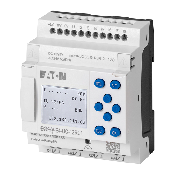
Page 98: Status Display On Easye4 Control Relays With Display And Keypad
3.3 Switch on 3.3.4 Status display on easyE4 control relays with display and keypad After being switched on, the easyE4 base device will start with the status display after the boot logo. The status display has six lines, with each one containing 16 characters. - Page 99 You can use the main menu from the status display in order to access the individual sub- menus. Press the OK button. The main menu will appear. Table 5: Main menu STOP ✓ RUN PARAMETERS SET CLOCK CARD INFORMATION SYSTEM-OPT. PROGRAM See also → chapter "3 Operation", page 127 easyE4 10/19 MN050009 EN www.eaton.com...
-
Page 100: Commissioning The Ethernet Network
3.3 Switch on 3.3.5 Commissioning the Ethernet network If you only want to communicate with one single easyE4, use an Ethernet cable to con- nect the easyE4 Ethernet port to your computer – please refer to → "Connecting the Eth- ernet cable", page 76... -
Page 101: Remote Operation
3. Commissioning 3.3 Switch on 3.3.6 Remote operation If you want to put the easyE4 device into operation without being present at the machine or system, make sure that you always know what exactly will happen when you do so. -
Page 102: Overview Of Switch-On Behavior
As soon as the easyE4 device starts, the options will be read. The easyE4 basic device will check whether a microSD has been inserted and whether there is a starting program on the microSD. The device will then switch to RUN or STOP mode depending on these parameters. - Page 103 Allow overwriting via card: If an microSD card with a starting program has been inserted, the device should load from the microSD card ② Options set again, since they could be overwritten by the loaded program easyE4 10/19 MN050009 EN www.eaton.com...
-
Page 104: Establishing An Ethernet Connection And Transferring A Program
3. Commissioning 3.5 Establishing an Ethernet connection and transferring a program 3.5 Establishing an Ethernet connection and transferring a program There is a connection via Ethernet that can be used to access the easyE4 base device for programming purposes. Physical connection Ethernet uses point-to-point connections, meaning that whenever more than two devices are connected, there needs to be a switch with a port for each device. - Page 105 3.5 Establishing an Ethernet connection and transferring a program Binary Decimal Subnet Mask 255.255.254.0 11111111 11111111 11111110 00000000 Network section 192.168.178.192 11000000 10101000 10110010 00000000 Table 7: Sample addresses for easyE4 easyE4 Decimal Binary IP Address 192.168.178.1 11000000 10101000 10110010 00000001 Subnet Mask 255.255.254.0...
- Page 106 3. Commissioning 3.5 Establishing an Ethernet connection and transferring a program Prerequisites that must be met in order to be able to access an easyE4 control relays: The PC must have an Ethernet port that is free and has been configured The PC's Ethernet port must be on the same subnet as the easyE4 base device.
- Page 107 Search for devices dialog box Figure 57: Search for devices with an IP address If there is an Ethernet connection, the easyE4 base device will be found and listed in the table with the corresponding parameters. Click on the Save as IP profile button to save the IP profile for the found easyE4 base device.
- Page 108 3. Commissioning 3.5 Establishing an Ethernet connection and transferring a program If a connection to multiple easyE4 base devices had already been established, there will be more entries available. In this case, select the IP address of the easyE4 base device you want under Interface.
- Page 109 When the project is loaded, the Ethernet settings in the project will be transferred to the easyE4 base device, or, more specifically: The parameter set under the Ethernet tab in the Project view will be transferred. Depending on how this set has been configured, the behavior of the Ethernet connection may change right after the project is loaded, and this may result in the device being disconnected.
-
Page 110: Automatic Booting From The Card
Since the RUN start option is enabled by default, the device will automatically switch to RUN mode. As soon as the easyE4 device switches to RUN mode, it will check whether there is a program in its internal memory. If there are none, the following step will be skipped. - Page 111 If this is the first time you click on this menu option, make sure to select the drive corresponding to the microSD card. The Card setup dialog box will appear. Transfer program Project/Card... menu option Figure 61: Offline dialog box for memory card Click the PC -> Card button. easyE4 10/19 MN050009 EN www.eaton.com...
- Page 112 <NET station NT1>. A plausibility check will then be run – please refer to → "Running a plausibility check," page 1. If this plausibility check is completed successfully, the following prompt will appear. easyE4 10/19 MN050009 EN www.eaton.com...
- Page 113 Figure 62: microSD memory card drive with PROGRAM folder contains BOOT.TXT and compiled test.prg program The card is now prepared with all the prerequisites for booting. You can now use auto- matic booting from the card – please refer to → "Automatic booting from the card", page 106. easyE4 10/19 MN050009 EN www.eaton.com...
-
Page 114: Preparing The Card In The Easye4 Device For Booting With Easysoft
3. Commissioning 3.6 Automatic booting from the card 3.6.2 Preparing the card in the easyE4 device for booting with easySoft 7 Prerequisites Licensed easySoft 7 version on the PC Insert the card into the device while the latter is de-energized. - Page 115 3. Commissioning 3.6 Automatic booting from the card Project/Card... menu option Figure 63: Offline dialog box for memory card easyE4 10/19 MN050009 EN www.eaton.com...
- Page 116 Select the NET station with the program that you want to transfer to the microSD memory card, e.g., <NET station NT1>. A plausibility check will then be run – please refer to → "Plausibility check", page 551. If the plausibility check is completed successfully, the following prompt will appear. easyE4 10/19 MN050009 EN www.eaton.com...
- Page 117 Figure 64: microSD memory card drive with PROGRAM folder contains BOOT.TXT and compiled test.prg program The card is now prepared with all the prerequisites for booting. You can now use auto- matic booting from the card – please refer to → "Automatic booting from the card", page 106. easyE4 10/19 MN050009 EN www.eaton.com...
-
Page 118: Preparing The Card For Booting On The Easye4 Device Itself
Prerequisites The microSD memory card must contain at least one compiled PRG program. The easyE4 device must be in STOP mode before it can be configured. If it is not, the device will point this out. Insert the memory card while the device is de-energized. - Page 119 Switch off the power supply. The card is now prepared with all the prerequisites for booting. You can now use auto- matic booting from the card – please refer to → "Automatic booting from the card", page 106. easyE4 10/19 MN050009 EN www.eaton.com...
-
Page 120: Reset - Resetting The Device To Factory Settings
Insert the microSD memory card. Switch on the easyE4 base device. Now turn off the easyE4 base device and remove the microSD memory card. The easyE4 base device will be reset. The program, password, and all settings will be deleted, and the network interface will work with auto-IP. -
Page 121: Updating Firmware
3. Commissioning 3.8 Updating firmware 3.8 Updating firmware As of firmware version V1.10, the firmware for the expansions in the easyE4 series can also be updated in addition to the base devices. The process varies for base devices and expansions. - Page 122 Updating the firmware for base devices All base devices can be updated with newer firmware. To find out which generation your easyE4 device belongs to, you can check the device menu or, during online communication with the easyE4 base device, the information in Communication view/HW Info tab.
- Page 123 Bootloader version 1.01: The configuration in the “e4update.ini” file will be read in the easyE4 bootloader and a compatibility check will be run. An update will not be carried out if the firmware on the device and the firmware on the card match.
- Page 124 The following applies when using bootloader version 1.00: If you do not remove the microSD memory card, the program will not start (when turn- ing on the device) until after the firmware is transferred again from the microSD memory card. easyE4 10/19 MN050009 EN www.eaton.com...
- Page 125 3.8 Updating firmware Firmware update expansion device An expansion device update must run via the device menu of a easyE4 base device. Expansion devices belonging to the first easyE4 generation (with firmware version 1.00) cannot be updated, as these devices do not have a bootloader physically. To find out which firmware version is found on the device, check the Communication view/HW Info tab during online communication.
- Page 126 Go to the main menu. Open the menu path SYSTEM OPTIONS\UPDATE\EXPANSION. Table 12: System option- s\Update UPDATE EXPANSION Select the number of the easyE4 expansion in the block; 1 to 11 are possible. Table 13: System option- s\Update\Expansion EXPANSION 1 -1 1 UPDATE F i l e n a m e 磣£¡¡¡¡££££££Ç...
- Page 127 3. Commissioning 3.8 Updating firmware See also → Section "Transfer program to the easyE4 device", page 153 → Section "Transferring programs from and to the microSD memory card", page → Section "Overview of switch-on behavior", page 98 → Section "Splash screen", page 565 →...
-
Page 128: Microsdmemory Card
3.9 microSDMemory card easyE4 base devices can be used with a microSD memory card. The easyE4 device supports microSD memory cards with a capacity of 128 MB to 32 GB (SD and SDHC, FAT12/16/32, Class 2 or 4 ). The following card manager functions for microSD memory cards and the online function are not available in demo mode. - Page 129 Use the P buttons to select the MANAGE SD CARD menu option and confirm your selection with OK. Use the P buttons to select the RELEASE CARD menu option and confirm your selection with OK. After this, the microSD memory card will no longer be accessible. easyE4 10/19 MN050009 EN www.eaton.com...
-
Page 130: Setting A Splash Screen For The Easy-E4
PC Figure 67: Storing the boot.bmp file As soon as the easyE4 device is switched on, the boot.bmp will be shown as a splash screen for the defined duration. In order for the splash screen to keep working, the microSD memory card must remain in the device. -
Page 131: Operation
LEDs' flashing patterns. → Section "Startup behavior of easyE4 control relays with LED indicators", page 88 4.1 Base device with display and buttons Figure 68: Display and keypad 4.1.1 LCD Display... -
Page 132: Display Color Backlight
The display's settings can be configured on the easyE4 device in the SYSTEM OPTIONS\SYSTEM\DISPLAY menu, → Section "Display", page 563 4.1.2 Keyboard... -
Page 133: Selecting Menus And Entering Values
To confirm a selection, press OK. to open the corresponding menu path. If necessary, use the cursor buttons while in a line to toggle between the right and left display areas. If this option is available, the character will appear. ó easyE4 10/19 MN050009 EN www.eaton.com... -
Page 134: Cursor Display
4. Operation 4.1 Base device with display and buttons 4.1.4 Cursor display The cursor buttons in the easyE4 program perform three functions: Move Enter Connect The current mode is indicated by the appearance of the flashing cursor. Current selection flashes on the easyE4 display... -
Page 135: Operating Modes Of The Easye4
The NET is run (Ethernet, web server, and Modbus TCP). the process image of the outputs is transferred to the physical outputs. The easyE4 devices with a display do not start with RUN mode if you deactivate the RUN MODE startup behavior. - Page 136 The main menu on the display is used to switch between operating modes, i.e., from RUN to STOP and vice versa,→ Section "STOP RUN operating mode menu", page 135 If a program has not been stored on the easyE4, it will not be possible to switch to RUN mode.
-
Page 137: Operation Of The Menu Selection And Value Entry
Change contact / relay. Insert new; save settings P1 input when used as P button P2 input when used as P button P3 input when used as P button P4 input when used as P button easyE4 10/19 MN050009 EN www.eaton.com... -
Page 138: Selecting A Device Menu
Table 16: Main menu STOP ✓ RUN PARAMETERS SET CLOCK CARD INFORMATION SYSTEM-OPT. PROGRAM A horizontal scroll bar indicates that other selection options are available. You may be able to reach them using the cursor keys easyE4 10/19 MN050009 EN www.eaton.com... -
Page 139: Overview Of The Menus On The Device
4.4.2 STOP RUN operating mode menu This submenu can be used to switch between operating modes. Table 19: STOP Table 20: RUN STOP ✓ RUN STOP? RUN? STOP RUN ✓ See also → Section "Operating modes of the easyE4", page 131 easyE4 10/19 MN050009 EN www.eaton.com... -
Page 140: Menu Parameter
Pressing the OK button will show the parameters for the individual function blocks in an additional submenu that can be used to modify these parameters with the cursor but- tons. Table 24: Time function block example T 01 Ü >I1 >I2 QV> easyE4 10/19 MN050009 EN www.eaton.com... -
Page 141: Set Clock Menu
4.4.4 Set clock menu This submenu can be used to set the date and time, select the display format for the date, and adjust the daylight saving time and radio clock settings on the easyE4 device. Opens additional menus Table 25: Set clock... -
Page 142: Menu Card
FREE XXXMB See also → Section "microSD memory card", page 1 → Section "Transferring programs from and to the microSD memory card", page → Section "Configuring the microSD card and device ID", page 586 easyE4 10/19 MN050009 EN www.eaton.com... -
Page 143: Menuinformation
4. Operation 4.4 Overview of the menus on the device 4.4.6 MenuInformation Shows the current status of the easyE4 device. Opens additional menus, The submenu is only provided in English Table 37: Main menu Table 38: Information Information\Actual Config STOP ✓ RUN... -
Page 144: System Options Menu
FRANCAIS ESPAŇOL ITALIANO NEDERLANDS POLSKI ČESKÝ PORTUGUÊS РУССКИЙ TÜRKÇE ROMÂNĀ MAGYAR Table 44: System option- Deletes the program in s\Delete progr. the easyE4 device. DELETE PROGR.? System options\Net The submenu is only provided in English easyE4 10/19 MN050009 EN www.eaton.com... - Page 145 → Section "Setting up a NET", page 625 → Section "Setting up a web server", page 646 → Section "Modbus TCP", page 632 → Section "E-mail function", page 670 → Section "microSD memory card", page 1 easyE4 10/19 MN050009 EN www.eaton.com...
-
Page 146: Program Menu
4.4 Overview of the menus on the device 4.4.8 Program menu This menu will only be available if the easyE4 is configured with its factory settings and/or when a program created with the EDP programming lan- guage has been stored on the easyE4 device. - Page 147 After editing the function blocks, the CANCEL and SAVE options will be available. Table 50: Program\Circuit dia- Table 51: Program\Function gram blocks SAVEÓ CANCELÓ easyE4 10/19 MN050009 EN www.eaton.com...
-
Page 148: Your First Edp Program
The easyE4 program will take care of the entire wiring for these components. All you have to do is then connect to the easyE4 any switches, sensors, lamps or con- tactors you wish to use. - Page 149 The cursor flashes at the top left, which is where you will start to wire your circuit dia- gram. Circuit diagram display Figure 70: Empty circuit diagram The last line shows the cursor's position: L: = Rung (Line). C: = Contact or coil field (Column). Amount of free memory in bytes. easyE4 10/19 MN050009 EN www.eaton.com...
-
Page 150: Draw A Wiring Diagram
The easyE4 automatically connects the contact to the power supply. The following example is provided for a lighting control. The easyE4 device takes on the wiring and the tasks of the circuit shown below. easyE4 10/19 MN050009 EN www.eaton.com... - Page 151 Q001 From the first contact to the output coil With easyE4 devices wire from the input to the output. The first input contact is I001 Press the OK button. easyE4 will insert the first contact, , at the cursor position.
- Page 152 When you move the arrow onto a contact or relay coil, it changes back to the cursor and can be reactivated if required. The easyE4 device automatically connects adjacent contacts up to the coil. Press the ALT to wire the cursor from through to the coil field.
-
Page 153: Testing The Circuit Diagram
Go back to the main menu. Select the STOP RUN menu option. The current operating mode is indicated on the display of the easyE4 device by a tick at RUN or STOP stop. Pressing the OK button enables you to toggle between the modes. -
Page 154: Control Options In Run Mode
Test using the power flow display Change to the circuit diagram display and press pushbutton S1. The relay picks up and the easyE4 displays the power flow with a double line. I001===I002===========Ä Q001 Figure 76: Power flow display 1 Power flow display: Inputs I001 and I002 are closed, relay Q1 has picked up Press pushbutton S2, that has been connected as a break contact. - Page 155 Press the ALT button. The zoom function will be turned off and the display will switch to the display status with contact and/or coil designations. Power flow display: Input I01 is closed, input I02 is open, relay Q1 has dropped out. easyE4 10/19 MN050009 EN www.eaton.com...
-
Page 156: Delete Program
NET parameterization. Proceed as follows to delete the program in the easyE4 device: easyE4 must be in STOP mode in order to extend, delete or modify the circuit diagram. Switch the easyE4 device to STOP mode. From the main menu, go to the SYSTEM OPTIONS menu. -
Page 157: Transfer Program To The Easye4 Device
4. Operation 4.6 Transfer program to the easyE4 device 4.6 Transfer program to the easyE4 device There are two options for directly transferring a finished .e70 program to an easyE4 device. With a microSD memory card With a direct Ethernet connection between the PC and easyE4 4.6.1 Transfer with a microSD memory card... - Page 158 4. Operation 4.6 Transfer program to the easyE4 device Click on the Project\ Card... menu option. easySoft 7 Project view Figure 80: Sample program open In the Select Folder dialog box that appears, select a folder where the LOGS and PROGRM folders that easySoft 7 needs should be created.
- Page 159 4. Operation 4.6 Transfer program to the easyE4 device The Card setup dialog box will appear. easySoft 7 Project View\Project\Card... Figure 81: Card setup dialog box You can use the Card section to specify the storage location, i.e., the drive, where the microSD memory card is located.
- Page 160 4. Operation 4.6 Transfer program to the easyE4 device Use this dialog box to enter the name that the program should have on the easyE4 device. Please make sure that this name does not have more than 14 characters (only letters and numbers are permitted).
- Page 161 Close the window Remove the microSD memory card from the drive. Insert the microSD memory card into the slot on the easyE4 base device. → Section "Inserting a microSD card", page 73 The easyE4 device will be ready for operation.
-
Page 162: Establish Ethernet Connection
This capability can be in the form of a local Ethernet port on the PC or a standard adapter (e.g., USB-to-Ethernet adapter). The PC's and the easyE4 base device's IP addresses must fall within the same range, i.e., the addresses' first two or three numbers must be the same, while the last number must be different and not equal to 0. - Page 163 Example using Windows Figure 84: Ethernet connection on PC You can now connect to your easySoft 7 device with the easyE4 programming soft- ware. See also → Section "Establishing an Ethernet connection and transferring a program", page...
- Page 164 4. Operation 4.6 Transfer program to the easyE4 device easyE4 10/19 MN050009 EN www.eaton.com...
-
Page 165: Programming On The Device
Programs/Circuit Diagram Figure 85: Circuit diagram display You wire contacts and coils of relays in the easyE4 circuit diagram from left to right, from the contact to the coil. The circuit diagram is created on a hidden wiring grid containing contact fields, coil fields and rungs. - Page 166 There are 256 rungs available in the circuit diagram, for wiring contacts and coils. For greater legibility the circuit diagram of the easyE4 device shows two contacts or one contact plus coil in a row on each rung. A total of 16 characters per circuit con- nection and five circuit connections plus the status line can be displayed sim- ultaneously.
-
Page 167: Circuit Diagram Elements
5.3 Circuit diagram elements 5.3 Circuit diagram elements A circuit diagram is a series of commands that the easyE4 device processes cyclically in RUN operating mode. Coils and contacts are interconnected in the circuit diagram. In RUN mode, a coil is switched on or off depending on the power flow and coil function set. -
Page 168: Contacts
Contacts such as N/O contacts are set to 1 when they are closed and 0 when they are opened. In the easyE4 circuit diagram you can wire contacts as make or break con- tacts. N/C contacts are indicated with a horizontal line above the operand concerned. -
Page 169: Coils
The options for setting output and marker relays are listed with the description of each coil function. A easyE4 device is provided with different types of relays and function blocks which can be wired in a circuit diagram via their coils (inputs). - Page 170 Figure 87: Impulse relay signal diagram A coil is automatically switched off in the event of a power failure and in STOP mode. Exception: retentive coils retain the 1 state. See also → Section "Retention function", page 578 easyE4 10/19 MN050009 EN www.eaton.com...
- Page 171 I 05---------------S Q 01 I 10---------------R Q 01 Q 01 Figure 89: Simultaneous triggering of The above example shows the Reset coil with priority when the Set and Reset coil are triggered at the same time. easyE4 10/19 MN050009 EN www.eaton.com...
- Page 172 This function is used if the coil is only meant to switch on a rising edge. When the coil status changes from 0 to 1, the coil switches its make contacts to 1 for one cycle. Figure 91: Signal diagram of cycle pulse with rising edge easyE4 10/19 MN050009 EN www.eaton.com...
- Page 173 1 to 0, the coil switches its make contacts to 1 for one cycle. Figure 92: Signal diagram of cycle pulse with negative edge A set coil is automatically switched off in the event of a power failure and in STOP mode. Retentive coils keep their logic state. easyE4 10/19 MN050009 EN www.eaton.com...
-
Page 174: Working With Contacts And Coils
5.4 Working with contacts and coils 5.4 Working with contacts and coils Switches, pushbuttons and relays from a conventional hardwired circuit diagram are wired in the easyE4 circuit diagram via input contacts and relay coils. Hardwired Wired with an easyE4 device... -
Page 175: Entering And Modifying Contacts
5.4.1 Entering and modifying contacts Figure 94: Contact legend You choose an input contact in the easyE4 device by means of the contact name and the contact number. Example: Base device input contact or function block contact consists of the abbre- viated function block name, the number, and the contact function. -
Page 176: Changing An N/O Contact To An N/C Contact
Bear in mind that the active state of an N/C contact is 0. The 0 state of a contact may, however, be present if the station is missing or is operating incorrectly. The use of an N/C contact in the circuit diagram without evaluating the diagnostics bit may cause incorrect interpretations. easyE4 10/19 MN050009 EN www.eaton.com... -
Page 177: Entering And Modifying Coils
Use the cursor buttons to change the value at the position. The easyE4 device will exit input mode as soon as you exit a contact or coil field with cursor buttons or the OK button. easyE4 10/19 MN050009 EN www.eaton.com... -
Page 178: Deleting Contacts And Coils
5.4.4 Deleting contacts and coils Use the buttons to move the cursor to a free contact or coil field. Press the DEL pushbutton. The contact or the coil will be deleted, together with any connections. easyE4 10/19 MN050009 EN www.eaton.com... -
Page 179: Creating And Modifying Connections
Press the ALT button to leave Connect mode. The easyE4 device closes the mode automatically as soon as you have moved the arrow to an occupied contact or coil field. In a rung, the easyE4 device connects contacts and the con- nection to the relay coil automatically if no empty fields are between them. -
Page 180: Deleting Connections
The circuit diagram display shows three of the 256 rungs at the same time. Rungs out- side of the display, including empty rungs, are scrolled by easyE4 automatically in the circuit diagram display if you move the cursor beyond the top or bottom of the display. -
Page 181: Got To A Rung
SAVE menu. Press the OK button. The entire program, circuit diagram and function blocks will be saved. After saving, you will be returned to the previous menu from which you have opened the circuit diagram. easyE4 10/19 MN050009 EN www.eaton.com... -
Page 182: Exiting The Circuit Diagram Without Saving
If the required contact or coil is located above the point of calling, start the search at the beginning of the circuit diagram. If the search is successful, you will automatically reach the required contact or coil field in the circuit diagram. easyE4 10/19 MN050009 EN www.eaton.com... -
Page 183: Switching With The Cursor Buttons
5.4 Working with contacts and coils 5.4.13 Switching with the Cursor Buttons You can use the four cursor buttons on the easyE4 device as hardwired inputs in the cir- cuit diagram. The P buttons can be used for testing circuits or for manual operation. The button func- tion is a useful addition for service and commissioning tasks. -
Page 184: Checking The Circuit Diagram
5.4.14 Checking the circuit diagram The easyE4 device features an integrated power flow display with which you can fol- low the switching states of contacts, relay and function block coils during operation. -
Page 185: Jumps
The use of jumps in the function block diagram is explained in → "LB - Jump label", page 491 and → "JC - Conditional jump", page 486. The easyE4 device allows the use of up to 32 jumps. Circuit diagram elements for jumps in the circuit diagram... - Page 186 5.4 Working with contacts and coils Backward jumps cannot be executed due to the way in which easyE4 works. If the jump label does not come after the jump coil, the jump will be made to the end of the circuit diagram.
-
Page 187: Wiring Net Operands In The Circuit Diagram
This mode is displayed by a flashing operand. ú Use the cursor button to move the cursor to the position to the left of the operand. A flashing zero appears as the initial value. easyE4 10/19 MN050009 EN www.eaton.com... - Page 188 Put (PT) and Get (GT) are used in order to exchange double word operands via the NET. For more information on the manufacturer function blocks: → Section "Working with function blocks", page 191 → Section "Function blocks", page 216 easyE4 10/19 MN050009 EN www.eaton.com...
- Page 189 NET station 2 sends the status of the P button P01 via SN1 to NET station 1. 2 slave 1 slave Destination Source The relevant circuit diagram is as follows: On NET station 1 the status of P1 is associated via RN01 as a count pulse for the counter relay C01. easyE4 10/19 MN050009 EN www.eaton.com...
- Page 190 More information about the function blocks: → Section "Function blocks", page 216 NET marker N.., nB.., nW.., nD... Every station that the NET marker describes can read any of the other stations. Figure 107: 1 slave Figure 108: 2 slave easyE4 10/19 MN050009 EN www.eaton.com...
-
Page 191: Transferring Programs From And To The Microsd Memory Card
Programs are normally transferred from easySoft 7 to the device so that they can be run on the device. If the easyE4 base device has a microSD memory card, the program can also be stored on this memory card.→ Section "Automatic booting from the card", page 1 You can store multiple programs on a single memory card. -
Page 192: Configuration On Base Devices With A Display
Data can be written to a binary file by using the DL (Data Logger) manufacturer function block. These logs can be managed here. MANAGE CARD Used to format and eject the card INFORMATION Provides information on the card size and the amount of free space left easyE4 10/19 MN050009 EN www.eaton.com... -
Page 193: Program Submenu
Requirement: The following option must be enabled when creating the program in easySoft: Allow overwriting via card You can use this submenu to manage the programs on the easyE4. The program transfer menu offers the following options: Table 68: Card\Program SET BOOT PROG. - Page 194 SAVE PROG. Overwrites the selected program with the program from the easyE4 SAVE AS Makes it possible to save the current program on the easyE4 under a new name See also → Section "microSD memory card", page 1 → Section "Transferring programs from and to the microSD memory card", page...
-
Page 195: Working With Function Blocks
Or vice versa: you create the function block in the function block editor, define the para- meters and use it then in the circuit diagram. With easyE4 devices you can insert up to 255 manufacturer function blocks in the function block list. - Page 196 RUN to allow (+) or prevent (-) changes to be made to reference points (constants). You must at least confirm the +/- character with the OK button. easyE4 10/19 MN050009 EN www.eaton.com...
-
Page 197: Function Block List
Press the ESC button in order to save the circuit diagram with the newly added function block. Answer the subsequent SAVE prompt with the OK button. The circuit diagram is saved and the easyE4 device changes to the next higher menu level. 5.6.2 Function block list The function block list can be used to access the function block editor. -
Page 198: Configuring Parameters In The Function Block Editor
Parameter display (+ appears/ – does not appear) Block name Basic parameters Function block Variable, inputs operand for inputs Function block out- puts Variable, operand for outputs Figure 110: Manufacturer function block display in the function block editor easyE4 10/19 MN050009 EN www.eaton.com... - Page 199 If, for example, the T timing relay function block is driven with a negative time ref- erence, it will no longer switch as expected. You should therefore take care to exclude such situations, as the easyE4 device cannot foresee these when the parameters are assigned.
- Page 200 2. RUN: Only access to the basic parameters is possible. It is only possible to change input values at manufacturer function blocks if they are constants. The modified constants are used directly for further pro- easyE4 10/19 MN050009 EN www.eaton.com...
-
Page 201: Parameters Menu
To remove a function block, you must remove it from the circuit diagram and from the function block list. Requirement: The easyE4 device must be in STOP mode. Switch to the circuit diagram display by selecting Main menu -> PROGRAMS -> CIRCUIT DIAGRAM. - Page 202 Tips for working with manufacturer function blocks Current ACTUAL values are deleted when you switch off the power supply or switch the easyE4 device to STOP mode. Exception: Retentive data keeps its state, → Section "Retention function", page 578. The most recent actual values are transferred to the operands every cycle. The data function block is an exception.
- Page 203 This also enables the transfer of negative values. The following applies to RUN mode: A easyE4 device processes the manufacturer function block after a pass through the circuit diagram. This takes the last status of the coils into account.
-
Page 204: Using Operands In A Program
1 bit BOOL Output bit via NET (send) 1 bit BOOL Network marker 1 bit BOOL Network marker byte 8 bit BYTE Network marker word 16 bit WORD Network marker double word 32 bit DINT easyE4 10/19 MN050009 EN www.eaton.com... - Page 205 - NET station n marker ID: Diagnostic alarm – LE - Output backlight P buttons – I - Bit input – Q - Bit output from another FB Assigning operands Value inputs Value outputs Constant Markers: MB, MD, MW easyE4 10/19 MN050009 EN www.eaton.com...
- Page 206 Boolean states 0 or 1. A marker bit is also called an auxiliary relay. easyE4 devices also manage the marker bits in marker bytes (MB), marker words (MW) and in marker double words (MD). A marker byte consists of 8 marker bits, a marker word of 16 marker bits and a marker double word of 32 marker bits.
- Page 207 Observing the following wiring rules will prevent the double assignment of marker bits. For easyE4, use: Marker bytes, starting at MB13 Marker words, starting at MW07 Marker double words, starting at MD04 The following operand tables show how this works. easyE4 10/19 MN050009 EN www.eaton.com...
- Page 208 368…- 360…- 352…- 344…- 336…- 328…- 320…- 312…- 304…- 296…- 288…- 280…- 272…- 264…- Byte Wor- 512…- 504…- 496…- 488…- 480…- 472…- 464…- 456…- 448…- 440…- 432…- 424…- 416…- 408…- 400…- 392…- Byte Wor- Byte easyE4 10/19 MN050009 EN www.eaton.com...
- Page 209 5. Programming on the device 5.7 Using operands in a program Wor- Byte Wor- Byte Wor- Byte Wor- Byte Wor- Byte Wor- Byte Wor- easyE4 10/19 MN050009 EN www.eaton.com...
- Page 210 5. Programming on the device 5.7 Using operands in a program Byte Wor- Byte Wor- Byte Wor- Byte Wor- Byte Wor- Byte Wor- Byte Wor- easyE4 10/19 MN050009 EN www.eaton.com...
- Page 211 5. Programming on the device 5.7 Using operands in a program Byte Wor- Byte Wor- Byte Wor- Byte Wor- Byte Wor- Byte Wor- Byte easyE4 10/19 MN050009 EN www.eaton.com...
- Page 212 5. Programming on the device 5.7 Using operands in a program Wor- Byte Wor- Byte Wor- Byte Wor- Byte Wor- Byte Wor- Byte Wor- easyE4 10/19 MN050009 EN www.eaton.com...
- Page 213 5. Programming on the device 5.7 Using operands in a program Byte Wor- Wor- Wor- Wor- Wor- Wor- Wor- Wor- easyE4 10/19 MN050009 EN www.eaton.com...
- Page 214 5. Programming on the device 5.7 Using operands in a program Wor- Wor- Wor- Wor- Wor- Wor- Wor- Wor- Wor- easyE4 10/19 MN050009 EN www.eaton.com...
- Page 215 5. Programming on the device 5.7 Using operands in a program Wor- Wor- Wor- Wor- Wor- Wor- Wor- Wor- easyE4 10/19 MN050009 EN www.eaton.com...
- Page 216 5. Programming on the device 5.7 Using operands in a program Wor- Wor- Wor- Wor- Wor- Wor- Wor- Wor- easyE4 10/19 MN050009 EN www.eaton.com...
- Page 217 IC - Counter-controlled interrupt function block Interaction between main program and interrupt program IE - Edge-controlled interrupt function block IT - Time-controlled interrupt function block Interaction between main program and interrupt program See also Cross-reference list - Finding operands in a program easyE4 10/19 MN050009 EN www.eaton.com...
- Page 218 5. Programming on the device 5.7 Using operands in a program easyE4 10/19 MN050009 EN www.eaton.com...
- Page 219 10/19 MN050009 EN www.eaton.com...
-
Page 220: Function Blocks
→ page 364 TC - Three step controller → page 379 VC - Value limitation → page 384 Data and register function blocks BC - Block compare → page 388 BT - Block transfer → page 395 easyE4 10/19 MN050009 EN www.eaton.com... - Page 221 IT - Time-controlled interrupt function block → page 525 User function blocks – used to create custom function blocks User function blocks are only available in easySoft 7 UF - User function block → page 533 easyE4 10/19 MN050009 EN www.eaton.com...
-
Page 222: Manufacturer Function Blocks
6.1.1 Timer modules 6.1.1.1 HW - 7-day time switch (Hour Week) easyE4 devices feature a real-time clock with a date and time functionality. When combined with the HW, HY or WT, YT function blocks, this real-time clock makes it possible to implement the functionality of a weekly timer and year time switch. - Page 223 Assigning operands You can assign the following operands to the function block outputs that are numeric outputs: Assigning operands Value outputs MB, MD, MW - Markers NB, NW, ND - NET markers NET stations n easyE4 10/19 MN050009 EN www.eaton.com...
- Page 224 Constants can be edited on the + Call enabled device, as can function block para- meters when using the EDP pro- gramming language. Edit interrupt routine Clicking on this button will open the interrupt routine Simulation possible easyE4 10/19 MN050009 EN www.eaton.com...
- Page 225 Information on the battery back-up time are provided on → Section "Back-upof real- time clock", page 702 After being switched on, the control relay will always update its switching state based on all existing switching time settings and will switch Q1 accordingly. easyE4 10/19 MN050009 EN www.eaton.com...
- Page 226 The time switch is required to switch from 10:00 to 18:00 from Fridays to Sundays. Figure 112: Signal diagram The HW time switch must be assigned the following parameters: Figure 113: Tab with parameters in the Programming view easyE4 10/19 MN050009 EN www.eaton.com...
- Page 227 The time switch is required to switch from Mondays to Fridays between 6:30 and 9:00 and between 17:00 and 22:30. Figure 114: Signal diagram The HW time switch must be assigned the following parameters: Figure 115: Tab with parameters in the Programming view easyE4 10/19 MN050009 EN www.eaton.com...
- Page 228 The time switch is required to switch on at 18:00 on Tuesdays and switch off at 6:00 on Saturdays. Figure 116: Signal diagram The HW time switch must be assigned the following parameters: Figure 117: Tab with parameters in the Programming view easyE4 10/19 MN050009 EN www.eaton.com...
- Page 229 If the on time and off time are the same, the output Q1 is switched off. The HW time switch must be assigned the following parameters: Figure 119: Tab with parameters in the Programming view Settings Time overlap easyE4 10/19 MN050009 EN www.eaton.com...
- Page 230 The time switch is to switch for 24 hours. On time at 00:00 on Monday and off time at 00:00 on Tuesday. Figure 120: Signal diagram The HW time switch must be assigned the following parameters: Figure 121: Tab with parameters in the Programming view 24 hours setting easyE4 10/19 MN050009 EN www.eaton.com...
- Page 231 → Section "T - Timing relay", page 246 → Section "WT - Weekly timer (WeekTable)", page 268 → Section "YT - Year time switch (Year Table)", page 261 → Section "AC - Astronomic clock ", page 272 easyE4 10/19 MN050009 EN www.eaton.com...
-
Page 232: Hy - Year Time Switch (Hora Year)
6.1 Manufacturer function blocks 6.1.1.2 HY - Year time switch (Hora Year) easyE4 devices feature a real-time clock with a date and time functionality. When combined with the HW, HY or WT, YT function blocks, this real-time clock makes it possible to implement the functionality of a weekly timer and year time switch. - Page 233 ON. In the same way, the year time switch switches the contact off with the first detected OFF, irrespective of whether another channel still sup- plies the ON signal. Please note that the time switches can only be configured up to the year 2099. easyE4 10/19 MN050009 EN www.eaton.com...
- Page 234 ID: Diagnostic alarm LE - Output backlight P device buttons I - Bit input Q - Bit output Q - Bit output of a FB 2) Only on projects with ≥ 2 base devices on NET easyE4 10/19 MN050009 EN www.eaton.com...
- Page 235 OFF time that are accurate to the day for each channel. Parameter display Constants can be edited on the + Call enabled device, as can function block para- meters when using the EDP pro- gramming language. Simulation possible easyE4 10/19 MN050009 EN www.eaton.com...
- Page 236 The year time switch should switch on at 00:00 on day 01.01.2022 and switch off when the OFF year has elapsed at 00:00 on day 01.01.2031. The parameters are set in one channel. Refer to the → "Example 1: Select year range", page 234 below for this time range. easyE4 10/19 MN050009 EN www.eaton.com...
- Page 237 Refer to the → "Example 7: Overlapping ranges", page 237 below for these time ranges. In these cases, a time cannot be configured for switching, and switching will always occur for the entire day, from 00:00 to 24:00. This is a set configuration that cannot be modified at runtime. easyE4 10/19 MN050009 EN www.eaton.com...
- Page 238 The year time switch HY01 should switch on at 1 March , 00:00 h, and remain switched on until 1 November, 00:00 h. The HY year time switch must be assigned the following parameters: Programming view/HY01/Year time switch parameters tab Figure 125: Entry screen in the programming software easyE4 10/19 MN050009 EN www.eaton.com...
- Page 239 00:00 on day 28.12 of each year. The HY year time switch must be assigned the following parameters: Programming view/HY01/Year time switch parameters tab Figure 127: Entry screen in the programming software easyE4 10/19 MN050009 EN www.eaton.com...
- Page 240 10 of each year and switch off at 00:00 on day 17 of the month. The HY year time switch must be assigned the following parameters: Programming view/HY01/Year time switch parameters tab Figure 129: Entry screen in the programming software easyE4 10/19 MN050009 EN www.eaton.com...
- Page 241 → Section "T - Timing relay", page 246 → Section "WT - Weekly timer (WeekTable)", page 268 → Section "YT - Year time switch (Year Table)", page 261 → Section "AC - Astronomic clock ", page 272 easyE4 10/19 MN050009 EN www.eaton.com...
-
Page 242: Ot - Operating Hours Counter
6.1 Manufacturer function blocks 6.1.1.3 OT - Operating hours counter General easyE4 base devices provide 4 operating hours counter func- tion blocks, OT01 through OT04. These function blocks output minutes and seconds in addition to hours. A comparison with a reference value that can be entered makes it possible, for instance, to signal when maintenance work is due. - Page 243 Bit inputs Constant 0, constant 1 M – Markers RN - Input bit via NET SN - Output bit via NET (send) N - Net marker bit nN - NET marker bit NET station n easyE4 10/19 MN050009 EN www.eaton.com...
- Page 244 NET (send) N - Network marker bit LE - Output backlight Q - Bit output I - Bit input of a FB 2) Only on projects with ≥ 2 base devices on NET easyE4 10/19 MN050009 EN www.eaton.com...
- Page 245 → Section "T - Timing relay", page 246 → Section "WT - Weekly timer (WeekTable)", page 268 → Section "YT - Year time switch (Year Table)", page 261 → Section "AC - Astronomic clock ", page 272 easyE4 10/19 MN050009 EN www.eaton.com...
-
Page 246: Rc - Real-Time Clock
6.1 Manufacturer function blocks 6.1.1.4 RC - Real-time clock General easyE4 Base devices provide exactly one real-time clock RC01. This function block can be used to read the date and time value of the device's real-time clock. This value is output in seven individual parameters than can each be processed further indi- vidually. - Page 247 Time: hour Range of 00 to 23 Time: minute Range of 00 to 59 Time: second Range of 00 to 59 Assigning operands You can assign the following operands to the function block outputs that are numeric outputs: easyE4 10/19 MN050009 EN www.eaton.com...
- Page 248 Constants can be edited on the + Call enabled device, as can function block para- meters when using the EDP pro- gramming language. Simulation possible Other Retention The function block does not recognize retentive data. easyE4 10/19 MN050009 EN www.eaton.com...
- Page 249 → Section "T - Timing relay", page 246 → Section "WT - Weekly timer (WeekTable)", page 268 → Section "YT - Year time switch (Year Table)", page 261 → Section "AC - Astronomic clock ", page 272 easyE4 10/19 MN050009 EN www.eaton.com...
-
Page 250: T - Timing Relay
6.1 Manufacturer function blocks 6.1.1.5 T - Timing relay General easyE4 base devices provide 32 timing relays (timer) T01…T32. You can use a time relay to delay the switching duration and the ON and OFF times of a switch contact. The times can be set from a range of 5 ms to 99 h 59 min. - Page 251 You can assign the following operands to the function block inputs that are numeric inputs. Operators Value inputs Constant, timer constant MD, MW, MB - Markers NB, NW, ND - NET markers nNB, nND, nND- NET markers NET station n IA - Analog input QA - Analog output easyE4 10/19 MN050009 EN www.eaton.com...
- Page 252 Operand value 5999 -> Time value is 99 min, 59 s. Example of time range H:M: Operand value 5999 -> Time value is 99 h, 59 min. Operating mode This parameter defines the switch function of the timing relay. easyE4 10/19 MN050009 EN www.eaton.com...
- Page 253 Note Seconds:Milliseconds Resolution: 5 ms Configurable as a constant: 00.005 to 999.995 (s.ms) M : S Minutes:Seconds Resolution: 1 s Configurable as a constant: 00:01 to 99:59 (min:s) H : M Hours:Minutes Resolution: 1 min easyE4 10/19 MN050009 EN www.eaton.com...
- Page 254 Rule: Time setpoint = Variable value/60 Integer Number of hours, Residual Number of minutes, You can only use analog values as setpoints if the value of the analog input is stable. Fluctuating analog values impair a repro- ducible timing response. easyE4 10/19 MN050009 EN www.eaton.com...
- Page 255 Range A: The time runs down from the SET time value. Range B: The time does not elapse because the trigger coil drops out prematurely. Range C: The Stop coil stops the time from elapsing. easyE4 10/19 MN050009 EN www.eaton.com...
- Page 256 Range E: The Reset coil resets the relay and the contact. Range F: After the reset coil is activated, the switching contact is switched off and the internal time counter is reset. The function relay waits for a new trigger pulse. easyE4 10/19 MN050009 EN www.eaton.com...
- Page 257 Range C: The Reset coil resets the relay and the contact. After the reset coil drops out, the relay continues to work normally. Range D: The Reset coil resets the relay and the contact when the function block is timing out. easyE4 10/19 MN050009 EN www.eaton.com...
- Page 258 The SET time ts consists of t1 plus t2 (switch function not retriggerable). Range F: The trigger coil drops out twice. The ACTUAL time t1 is cleared and the SET time ts elapses completely (retriggerable switch function). easyE4 10/19 MN050009 EN www.eaton.com...
- Page 259 Range A: The relay processes the two times without any interruption. Range B: The trigger coil drops out before the on-delay is reached. Range C: The stop coil stops the timeout of the on-delay. Range D: The stop coil has no effect in this range. easyE4 10/19 MN050009 EN www.eaton.com...
- Page 260 4: Switching contact (N/O contact) T…Q1 Range A: The trigger signal is short and is lengthened. Range B: The trigger signal is longer than the SET time. Range C: The stop coil interrupts the timing out of the set time. easyE4 10/19 MN050009 EN www.eaton.com...
- Page 261 How the timing relay works with the flashing operating mode, synchronous and asynchronous Figure 138: Signal diagram timing relay, single pulse 1 1: Trigger coil T..EN 2: Stop coil T..ST easyE4 10/19 MN050009 EN www.eaton.com...
- Page 262 Range A: The relay flashes for as long as the trigger coil is activated. Range B: The stop coil interrupts the timing out of the set time. Range C: The reset coil resets the relay. easyE4 10/19 MN050009 EN www.eaton.com...
- Page 263 . A marker activates the reset coil, while another marker activates the stop coil. T 02Q1---------------------------Ä Q 01 Figure 140: Wiring of the function block contact The signal from the function block will go directly to the device output. easyE4 10/19 MN050009 EN www.eaton.com...
- Page 264 → Section "OT - Operating hours counter ", page 238 → Section "RC - Real-time clock", page 242 → Section "WT - Weekly timer (WeekTable)", page 268 → Section "YT - Year time switch (Year Table)", page 261 easyE4 10/19 MN050009 EN www.eaton.com...
-
Page 265: Yt - Year Time Switch (Year Table)
6.1 Manufacturer function blocks 6.1.1.6 YT - Year time switch (Year Table) easyE4 devices feature a real-time clock with a date and time functionality. When combined with the HW, HY or WT, YT function blocks, this real-time clock makes it possible to implement the functionality of a weekly timer and year time switch. - Page 266 ID: Diagnostic alarm LE - Output backlight P device buttons I - Bit input Q - Bit output Q - Bit output of a FB 2) Only on projects with ≥ 2 base devices on NET easyE4 10/19 MN050009 EN www.eaton.com...
- Page 267 (all four channels will act on output Q1). There is an ON time and an OFF time that are accurate to the day for each channel. Parameter display Constants can be edited on the + Call enabled easyE4 10/19 MN050009 EN www.eaton.com...
- Page 268 In these cases, a time cannot be configured for switching, and switching will always occur for the entire day, from 00:00 to 24:00. This is a set configuration that cannot be modified at runtime. This example uses all four available modes. easyE4 10/19 MN050009 EN www.eaton.com...
- Page 269 Year time switch YT01 should switch on on 12/05 of every year at 00:00 and remain switched on until 12/28 of every year at 00:00. The YT year time switch must be assigned the following parameters: easyE4 10/19 MN050009 EN www.eaton.com...
- Page 270 00:00 and switch off on the 17th at 00:00. The YT year time switch must be assigned the following parameters: Programming view/YT01/Year time switch (new) parameters tab Figure 146: Entry screen in the programming software easyE4 10/19 MN050009 EN www.eaton.com...
- Page 271 → Section "OT - Operating hours counter ", page 238 → Section "RC - Real-time clock", page 242 → Section "T - Timing relay", page 246 → Section "WT - Weekly timer (WeekTable)", page 268 → Section "AC - Astronomic clock ", page 272 easyE4 10/19 MN050009 EN www.eaton.com...
-
Page 272: Wt - Weekly Timer (Weektable)
6.1 Manufacturer function blocks 6.1.1.7 WT - Weekly timer (WeekTable) easyE4 devices feature a real-time clock with a date and time functionality. When combined with the HW, HY or WT, YT function blocks, this real-time clock makes it possible to implement the functionality of a weekly timer and year time switch. - Page 273 MB, MD, MW - Markers NB, NW, ND - NET markers NET stations n QA - Analog output I - Value input of a FB 2) Only on projects with ≥ 2 base devices on NET easyE4 10/19 MN050009 EN www.eaton.com...
- Page 274 If + Call enabled is selected for the function block under Function block dia- gram/Parameters/, it will be possible to change the switching times in the PARAMETER menu on the device while in RUN / STOP mode. easyE4 10/19 MN050009 EN www.eaton.com...
- Page 275 → Section "RC - Real-time clock", page 242 → Section "T - Timing relay", page 246 → Section "YT - Year time switch (Year Table)", page 261 → Section "AC - Astronomic clock ", page 272 easyE4 10/19 MN050009 EN www.eaton.com...
-
Page 276: Ac - Astronomic Clock
1.10 or higher for the project. General easyE4 base devices provide 32 astronomic clock function blocks, AC01 through AC32. Output Q1 in these function blocks is switched on during the time between sunrise and sunset. - Page 277 ID: Diagnostic alarm LE - Output backlight P device buttons I - Bit input Q - Bit output Q - Bit output of a FB 2) Only on projects with ≥ 2 base devices on NET easyE4 10/19 MN050009 EN www.eaton.com...
- Page 278 NET (send) N - Network marker bit LE - Output backlight Q - Bit output I - Bit input of a FB 2) Only on projects with ≥ 2 base devices on NET easyE4 10/19 MN050009 EN www.eaton.com...
- Page 279 0 or 1 depending on the func- tion block. Parameter display Constants can be edited on the + Call enabled device, as can function block para- meters when using the EDP pro- gramming language. Simulation possible easyE4 10/19 MN050009 EN www.eaton.com...
- Page 280 Figure 148: Sunrise and sunset in Bonn Drevja in Norway The following is the geodata for the Drevja location in Norway: Latidude: 65.9780775 Longitude: 13.2348074 The sun does not set during the summer months (day 165 to 180). easyE4 10/19 MN050009 EN www.eaton.com...
- Page 281 Longitude: 9.7329299 The sunrise and sunset times remain the same throughout the whole year with little variation. Figure 150: Offset; O1=-2; O2=2; Q1=1 will switch on 2 hours before sunrise and off 2 hours after sunset easyE4 10/19 MN050009 EN www.eaton.com...
- Page 282 Figure 152: Offset; O1=1; O2= -1; Q1 will switch on 1 hour after sunrise and off 1 hour before sunset Figure 153: Offset; O1=-2; O2=2; Q1=1 will switch on 2 hours before sunrise and off 2 hours after sunset easyE4 10/19 MN050009 EN www.eaton.com...
- Page 283 Longitude: 0 Offset O1 = 5 Offset O2 = -7 In the winter months, the switch-off time is before the switch-on time. This will cause function block output Q1=0 to always remain off during these months. easyE4 10/19 MN050009 EN www.eaton.com...
- Page 284 → Section "OT - Operating hours counter ", page 238 → Section "RC - Real-time clock", page 242 → Section "T - Timing relay", page 246 → Section "WT - Weekly timer (WeekTable)", page 268 easyE4 10/19 MN050009 EN www.eaton.com...
-
Page 285: Counter Function Blocks
You can set a lower and higher limit setpoint as comparison values for the counter relay function block, as well as a start value. General easyE4 base devices provide 32 counter relays, C01 through C32. Each counter relay can count up and down and functions as a double word counter. - Page 286 2) Only on projects with ≥ 2 base devices on NET You can assign the following operands to the function block inputs that are bit inputs: Operators Bit inputs Constant 0, constant 1 M – Markers RN - Input bit via NET easyE4 10/19 MN050009 EN www.eaton.com...
- Page 287 QA - Analog output I - Value input of a FB 2) Only on projects with ≥ 2 base devices on NET You can assign the following operands to the function block outputs that are bit outputs: easyE4 10/19 MN050009 EN www.eaton.com...
- Page 288 0 or 1 depending on the func- tion block. Parameter display Constants can be edited on the + Call enabled device, as can function block para- meters when using the EDP pro- gramming language. Simulation possible easyE4 10/19 MN050009 EN www.eaton.com...
- Page 289 9: Contact (N/O) C..FB: Lower threshold value reached or undershot. 10: C..ZE = 1, if actual value is zero 11: C..CY = 1, if the value is out of range. • Range A: – The counter range has the value zero. easyE4 10/19 MN050009 EN www.eaton.com...
- Page 290 See also → Section "CF - Frequency counter", page 287 → Section "CH - High-speed counter", page 293 → Section "CI - Incremental Counter", page 299 → Section "Timing and counter relay example", page 557 easyE4 10/19 MN050009 EN www.eaton.com...
-
Page 291: Cf - Frequency Counter
The value range cannot be exceeded as the maximum measured value is less than the value range. General easyE4 base devices provide 4 frequency counters CF01…CF04. These high-speed frequency counters are intern- ally connected with the digital inputs I01…I04 and operate inde- pendently of the cycle time. - Page 292 I03 counter input for counter CF03 I04 counter input for counter CF04 NOTICE Avoid unforeseeable switching states. Switch C, CF, CH, CI function blocks only at one single point in the pro- gram. Otherwise, previous counts will be overwritten. easyE4 10/19 MN050009 EN www.eaton.com...
- Page 293 ID: Diagnostic alarm LE - Output backlight P device buttons I - Bit input Q - Bit output Q - Bit output of a FB 2) Only on projects with ≥ 2 base devices on NET easyE4 10/19 MN050009 EN www.eaton.com...
- Page 294 There is a square wave signal with a frequency of 50 Hz at device input I01. Outputs QV and QF of function block CF01 will have the following values depending on the chosen measuring interval: easyE4 10/19 MN050009 EN www.eaton.com...
- Page 295 QV quency being measured can 0.1s 500 0.5s 2 500 1.0s 5 000 2.0s 10 000 5.0s 25 000 10.0s 50 000 Simulation possible Other Signal diagram easyE4 10/19 MN050009 EN www.eaton.com...
- Page 296 See also → Section "CF - Frequency counter", page 287 → Section "CH - High-speed counter", page 293 → Section "CI - Incremental Counter", page 299 → Section "Timing and counter relay example", page 557 easyE4 10/19 MN050009 EN www.eaton.com...
-
Page 297: High-Speed Counter
I3: Counter input for counter CH03. I4: Counter input for counter CH04. General easyE4 Base devices provide 4 high-speed counters CH01…CH 04. The high-speed up and down counters are internally hard- wired with the digital inputs I01...I04 and operate inde- pendently of the cycle time. - Page 298 QV - QV - Numeric output of a FB 1) Only on function blocks T, AC 2) Only on projects with ≥ 2 base devices on NET You can assign the following operands to the function block inputs that are bit inputs: easyE4 10/19 MN050009 EN www.eaton.com...
- Page 299 You can assign the following operands to the function block outputs that are numeric outputs: Assigning operands Value outputs MB, MD, MW - Markers NB, NW, ND - NET markers NET stations n QA - Analog output easyE4 10/19 MN050009 EN www.eaton.com...
- Page 300 0 or 1 depending on the func- tion block. Parameter display Constants can be edited on the + Call enabled device, as can function block para- meters when using the EDP pro- gramming language. Simulation possible easyE4 10/19 MN050009 EN www.eaton.com...
- Page 301 9: Contact (N/O) CH..FB: Lower threshold value reached or undershot. 10: CH..ZE = 1, if actual value is zero. 11: CH..CY = 1, if the value is out of range • Range A: – The counter range has the value zero. easyE4 10/19 MN050009 EN www.eaton.com...
- Page 302 RUN mode, the counter relay will continue to work with the non- volatile actual value. See also → "C - Counter relay", page 281 → "CH - High-speed counter", page 293 → "CI - Incremental Counter", page 299 → "Timing and counter relay example", page 557 easyE4 10/19 MN050009 EN www.eaton.com...
-
Page 303: Ci - Incremental Counter
I3: Counter input for counter CI02, channel A. I4: Counter input for counter CI02, channel B. General information easyE4 base devices provide 2 high-speed incremental encoder counters, CI01 through CI02. The high-speed up and down coun- ters are internally hardwired with the digital inputs I01...I02 or I03...I04 and operate independently of the cycle time. - Page 304 Figure 161: CI function block counting down; QV=QV-4 NOTICE Avoid unforeseeable switching states. Switch C, CF, CH, CI function blocks only at one single point in the pro- gram. Otherwise, previous counts will be overwritten. easyE4 10/19 MN050009 EN www.eaton.com...
- Page 305 Constant 0, constant 1 M – Markers RN - Input bit via NET SN - Output bit via NET (send) N - Net marker bit nN - NET marker bit NET station n ID: Diagnostic alarm easyE4 10/19 MN050009 EN www.eaton.com...
- Page 306 Current counter value in RUN mode The pulses at channel A and channel B are counted. 2 pulses are counted per counting period. Example: 2 pulses at channel A and 2 pulses at channel B; value at CI..QV = 4 easyE4 10/19 MN050009 EN www.eaton.com...
- Page 307 0 or 1 not do anything. depending on the function block. Parameter display Constants can be edited on the device, + Call enabled as can function block parameters when using the EDP programming language. Simulation pos- sible easyE4 10/19 MN050009 EN www.eaton.com...
- Page 308 7: Contact (N/O) CI..OF: Upper limit threshold reached or exceeded. 8: Contact (N/O) CI..FB: Lower threshold value reached or undershot. 9: CI..ZE = 1, if actual value is zero 10: CI..CY = 1, if the value is out of range. easyE4 10/19 MN050009 EN www.eaton.com...
- Page 309 See also → Section "CI - Incremental Counter", page 299 → Section "CF - Frequency counter", page 287 → Section "CH - High-speed counter", page 293 → Section "Timing and counter relay example", page 557 easyE4 10/19 MN050009 EN www.eaton.com...
-
Page 310: Arithmetic And Analog Function Blocks
An analog value comparator or threshold value switch is used, for example, to compare analog values or marker contents and switch when defined threshold values are reached. General easyE4 base devices provide 32 analog comparators, A01 through A32. Analog comparators can be used to compare analog input values with a reference value. - Page 311 QV - QV - Numeric output of a FB 1) Only on function blocks T, AC 2) Only on projects with ≥ 2 base devices on NET You can assign the following operands to the function block inputs that are bit inputs: easyE4 10/19 MN050009 EN www.eaton.com...
- Page 312 MB, MD, MW - Markers NB, NW, ND - NET markers NET stations n QA - Analog output I - Value input of a FB 2) Only on projects with ≥ 2 base devices on NET easyE4 10/19 MN050009 EN www.eaton.com...
- Page 313 0 or 1 depending on the func- tion block. Parameter display Constants can be edited on the + Call enabled device, as can function block para- meters when using the EDP pro- gramming language. Simulation possible easyE4 10/19 MN050009 EN www.eaton.com...
- Page 314 – If the hysteresis limit is undershot with the actual value decreasing. • Range D: I1 with offset leaves the permissible value range. The contact CY closes. CY opens as soon as I1 with offset is once more within the value range. easyE4 10/19 MN050009 EN www.eaton.com...
- Page 315 → Section "CP – Comparator", page 326 → Section "LS - Value scaling", page 330 → Section "MM - Min-/Max function", page 335 → Section "PW - Pulse width modulation", page 345 → Section "PM - Performance map ", page 339 easyE4 10/19 MN050009 EN www.eaton.com...
-
Page 316: Ar - Arithmetic
General easyE4 Base devices provide 32 arithmetic function blocks, AR01 through AR32. These function blocks can be used to carry out the four basic arithmetic operations: addition, subtraction, multiplication, and division. - Page 317 Status 1 if the above value range is exceeded. Status 1 if the value of the function block output QV (the calculation result) equals zero (DWord) Current counter value in RUN mode Integer value range: -2,147,483,648 to +2,147,483,647 easyE4 10/19 MN050009 EN www.eaton.com...
- Page 318 EDP pro- gramming language. Simulation possible Addition example 42 + 1000 = 1042 2147483647 + 1 = Last valid value before this arithmetic operation, due to overflow (Carry) AR..CY = 1 -2048 + 1000 = -1048 easyE4 10/19 MN050009 EN www.eaton.com...
- Page 319 AR04 ADD + >I1 >I2 QV> Figure 166: Parameters on the device display Enter the function block settings here. The display contains the following elements: AR04 arithmetic Function block:Arithmetic function block easyE4 10/19 MN050009 EN www.eaton.com...
- Page 320 → Section "AR - Arithmetic", page 312 → Section "CP – Comparator", page 326 → Section "LS - Value scaling", page 330 → Section "MM - Min-/Max function", page 335 → Section "PW - Pulse width modulation", page 345 easyE4 10/19 MN050009 EN www.eaton.com...
-
Page 321: Av - Average
1.10 or higher for the project. General easyE4 base devices provide 32 average function blocks, AV01 through AV32. Averaging is a method used to smooth data series, and is primarily used, for example, to smooth temperatures or pro- duction data recorded over several hours or days by removing high frequency components. - Page 322 I1 will be taken into account. The currently calculated average value will be output at function block output QV. Mean- while, function block output QN will indicate how many values were read at I1 and used for the calculation. easyE4 10/19 MN050009 EN www.eaton.com...
- Page 323 Bit inputs Constant 0, constant 1 M – Markers RN - Input bit via NET SN - Output bit via NET (send) N - Net marker bit nN - NET marker bit NET station n easyE4 10/19 MN050009 EN www.eaton.com...
- Page 324 QA - Analog output I - Value input of a FB 2) Only on projects with ≥ 2 base devices on NET You can assign the following operands to the function block outputs that are bit outputs: easyE4 10/19 MN050009 EN www.eaton.com...
- Page 325 Parameter display Constants can be edited on the + Call enabled device, as can function block para- meters when using the EDP pro- gramming language. Simulation possible easyE4 10/19 MN050009 EN www.eaton.com...
- Page 326 Continuous operation average value EMA(n) = ROUND [ EMA +SF* ( I1 – EMA EMA(n) = Currently calculated exponential moving average n = 1…NO SF = Smoothing factor; value between 0 and 1 = Value at function block input I1; e.g., temperature value easyE4 10/19 MN050009 EN www.eaton.com...
- Page 327 In the example, the average value in continuous mode is calculated for the 24th value: EMA(23) = ROUND [ EMA(22)+0.08*( I1(23) – EMA(22) ] EMA(23) = ROUND [ 2035 + 0.08* (2004 – 2035) ] EMA(23) = ROUND [2032.52 ] = 2033 easyE4 10/19 MN050009 EN www.eaton.com...
- Page 328 20.11 20.25 20.33 20.41 20.43 20.42 20.54 – 20.67 – 20.79 – 20.92 – 21.08 – 21.29 – 21.50 – … … … … … – Retention The function block does not recognize retentive data. easyE4 10/19 MN050009 EN www.eaton.com...
- Page 329 → Section "MM - Min-/Max function", page 335 → Section "PM - Performance map ", page 339 → Section "PW - Pulse width modulation", page 345 → Section "FT - PT1-Signal smoothing filter ", page 358 easyE4 10/19 MN050009 EN www.eaton.com...
-
Page 330: Cp - Comparator
6.1.3.4 CP – Comparator This function block is used to compare variables and/or constants with each other. General easyE4 base devices provide 32 comparator function blocks (Compare) CP01 to CP32. Comparators are used to compare variables and constants with each other and output the relationship between them: Less than / Equal to / Greater than. - Page 331 QA - Analog output I - Value input of a FB 2) Only on projects with ≥ 2 base devices on NET You can assign the following operands to the function block outputs that are bit outputs: easyE4 10/19 MN050009 EN www.eaton.com...
- Page 332 Example of a CP configuration on a device display When using the function block in the circuit diagram for the first time, use OK to auto- matically enter the display of function blocks on the device display, as shown in the easyE4 10/19 MN050009 EN www.eaton.com...
- Page 333 → Section "AV - Average", page 317 → Section "LS - Value scaling", page 330 → Section "MM - Min-/Max function", page 335 → Section "PW - Pulse width modulation", page 345 → Section "PM - Performance map ", page 339 easyE4 10/19 MN050009 EN www.eaton.com...
-
Page 334: Ls - Value Scaling
6.1 Manufacturer function blocks 6.1.3.5 LS - Value scaling General easyE4 base devices provider 32 value scaling function blocks, LS01 through LS32. These function blocks can be used to transfer values from one value range to another. More specifically, a value scaling func- tion block will take one of the mathematical relationships you have specified and use it to scale the value at input LS..I1 in... - Page 335 The mathematical relationship is follows: m = Gradient Y0 = Y offset when X = 0 X1, Y1 = First value pair X2, Y2 = Second value pair g = Straight line with positive gradient Figure 172: Mathematical interrelationship easyE4 10/19 MN050009 EN www.eaton.com...
- Page 336 RN - Input bit via NET SN - Output bit via NET (send) N - Net marker bit nN - NET marker bit NET station n ID: Diagnostic alarm LE - Output backlight P device buttons easyE4 10/19 MN050009 EN www.eaton.com...
- Page 337 NET (send) N - Network marker bit LE - Output backlight Q - Bit output I - Bit input of a FB 2) Only on projects with ≥ 2 base devices on NET easyE4 10/19 MN050009 EN www.eaton.com...
- Page 338 → Section "AR - Arithmetic", page 312 → Section "CP – Comparator", page 326 → Section "MM - Min-/Max function", page 335 → Section "PW - Pulse width modulation", page 345 → Section "PM - Performance map ", page 339 easyE4 10/19 MN050009 EN www.eaton.com...
-
Page 339: Mm - Min-/Max Function
6.1 Manufacturer function blocks 6.1.3.6 MM - Min-/Max function General easyE4 base devices provide 32 Min-/Max function blocks, MM01 through MM32. These function blocks can be used to determine the maximum value and the minimum value of a changing analog value. This makes it, for example, easy to conveniently determine the mag- nitude of the pressure fluctuations inside a system. - Page 340 This message will only be displayed for or maximum value has been entered one cycle (DWord) Minimum value of I1 that was sampled during the active period Maximum value of I1 that was sampled during the active period easyE4 10/19 MN050009 EN www.eaton.com...
- Page 341 Constants can be edited on the + Call enabled device, as can function block para- meters when using the EDP pro- gramming language. Simulation possible Other Retention The function block does not recognize retentive data. easyE4 10/19 MN050009 EN www.eaton.com...
- Page 342 → Section "AR - Arithmetic", page 312 → Section "CP – Comparator", page 326 → Section "LS - Value scaling", page 330 → Section "PW - Pulse width modulation", page 345 → Section "PM - Performance map ", page 339 easyE4 10/19 MN050009 EN www.eaton.com...
-
Page 343: Pm - Performance Map
1.10 or higher for the project. General easyE4 base devices provide 4 performance map function blocks, PM01 through PM04. This characteristic curve function is imple- mented by reading the value at function block input I1, looking up the corresponding output value in a reference value table, and out- putting this output value at function block output QV. - Page 344 ID: Diagnostic alarm LE - Output backlight P device buttons I - Bit input Q - Bit output Q - Bit output of a FB 2) Only on projects with ≥ 2 base devices on NET easyE4 10/19 MN050009 EN www.eaton.com...
- Page 345 QA - Analog output I - Value input of a FB 2) Only on projects with ≥ 2 base devices on NET You can assign the following operands to the function block outputs that are bit outputs: easyE4 10/19 MN050009 EN www.eaton.com...
- Page 346 Parameter display Constants can be edited on the + Call enabled device, as can function block para- meters when using the EDP pro- gramming language. Simulation possible easyE4 10/19 MN050009 EN www.eaton.com...
- Page 347 Value at QV as a function of at I1 the operating mode Interpolating: 1 Next higher value: 2 Next lower value: 0 Nearest value: 2 Interpolating: 3 Next higher value: 3 Next lower value: 2 Nearest value: 3 Interpolating: 4 easyE4 10/19 MN050009 EN www.eaton.com...
- Page 348 → Section "AV - Average", page 317 → Section "CP – Comparator", page 326 → Section "LS - Value scaling", page 330 → Section "MM - Min-/Max function", page 335 → Section "PW - Pulse width modulation", page 345 easyE4 10/19 MN050009 EN www.eaton.com...
-
Page 349: Pw - Pulse Width Modulation
6.1 Manufacturer function blocks 6.1.3.8 PW - Pulse width modulation General easyE4 base devices provide two function blocks for pulse width modulation PW01…PW02. These function blocks generate a pulse train with a constant period. The main application for PW function blocks is when working with devices that feature transistor outputs. - Page 350 0 and 1023, you will have to normalize this value first of all. If you require an integral normalization factor, in this case the factor of 4, only multiplication with the AR arithmetic function block is required. easyE4 10/19 MN050009 EN www.eaton.com...
- Page 351 If the duration is below the set minimum on duration or minimum off duration, the Boolean control output E1 is set to 1. This control output E1 is used for monitoring during commissioning and does not have to be connected. easyE4 10/19 MN050009 EN www.eaton.com...
- Page 352 ID: Diagnostic alarm LE - Output backlight P device buttons I - Bit input Q - Bit output Q - Bit output of a FB 2) Only on projects with ≥ 2 base devices on NET easyE4 10/19 MN050009 EN www.eaton.com...
- Page 353 0 or 1 depending on the func- tion block. Parameter display Constants can be edited on the + Call enabled device, as can function block para- meters when using the EDP pro- gramming language. Simulation not possible easyE4 10/19 MN050009 EN www.eaton.com...
- Page 354 → Section "AR - Arithmetic", page 312 → Section "CP – Comparator", page 326 → Section "LS - Value scaling", page 330 → Section "MM - Min-/Max function", page 335 → Section "PM - Performance map ", page 339 easyE4 10/19 MN050009 EN www.eaton.com...
-
Page 355: Open-Loop And Closed-Loop Function Blocks
6.1 Manufacturer function blocks 6.1.4 Open-loop and closed-loop function blocks 6.1.4.1 DC - PID controller General easyE4 The base devices provide 32 PID controller function blocks DC01...DC32. Operating principle A closed-loop control circuit with a PID controller consists of the following com-... - Page 356 ED all need to be active in order for the proportional term, integral term, and derivative term to be calculated. Example: If only coils DC…EP and DC…EI are activated, the PID controller operates as a PI controller. easyE4 10/19 MN050009 EN www.eaton.com...
- Page 357 Manual manipulated variable When UNP mode is selected: and neg- Value range: -4096 ... +4095 ative values are entered at MV, the func- tion block returns a zero at output QV. easyE4 10/19 MN050009 EN www.eaton.com...
- Page 358 → "ST - Set cycle time", page 503. A combination of two devices easyE4 is ideal for applications requiring lengthy calculations or visualizations such as PID closed-loop control tasks with the PID controller and also visu- alization functions at the same time.
- Page 359 QA - Analog output I - Value input of a FB 2) Only on projects with ≥ 2 base devices on NET You can assign the following operands to the function block outputs that are bit outputs: easyE4 10/19 MN050009 EN www.eaton.com...
- Page 360 DC02EP d-Ä DC02EI v-Ä DC02ED M 52-----------------------------Ä DC02SE Figure 174: Wiring the function block coils The function block coils are activated by markers. DC02LI---------------------------Ä S M 96 Figure 175: Wiring of the function block contact easyE4 10/19 MN050009 EN www.eaton.com...
- Page 361 → Section "TC - Three step controller", page 379 → Section "VC - Value limitation ", page 384 → Section "BC - Block compare", page 388 → Section "BV - Boolean operation", page 444 → Section "PO - Pulse output", page 364 easyE4 10/19 MN050009 EN www.eaton.com...
-
Page 362: Ft - Pt1-Signal Smoothing Filter
I1 during the first processing cycle. This will speed up the PT1 starting behavior. Step response of the function block The step response of the FT-PT1 function is an e function. After a time t = Tg the nor- malized output value is 0.63 QV/QVmax. easyE4 10/19 MN050009 EN www.eaton.com... - Page 363 (by a factor of approximately 10): T A =10 ∙ t cyc . The sample time is set indirectly with the value for recovery time T G (please refer to the table above). The following therefore applies: t cyc << T A . easyE4 10/19 MN050009 EN www.eaton.com...
- Page 364 You can assign the following operands to the function block inputs that are numeric inputs. Operators Value inputs Constant, timer constant MD, MW, MB - Markers NB, NW, ND - NET markers nNB, nND, nND- NET markers NET station n IA - Analog input easyE4 10/19 MN050009 EN www.eaton.com...
- Page 365 QA - Analog output I - Value input of a FB 2) Only on projects with ≥ 2 base devices on NET You can assign the following operands to the function block outputs that are bit outputs: easyE4 10/19 MN050009 EN www.eaton.com...
- Page 366 Enter the function block settings here. FT17 + >I1 >TG >KP QV> Figure 179: Parameters shown on display easyE4 10/19 MN050009 EN www.eaton.com...
- Page 367 → Section "TC - Three step controller", page 379 → Section "VC - Value limitation ", page 384 → Section "BC - Block compare", page 388 → Section "BV - Boolean operation", page 444 → Section "PO - Pulse output", page 364 easyE4 10/19 MN050009 EN www.eaton.com...
- Page 368 6.1.4.3 PO - Pulse output General The DC versions of easyE4 base devices provide 2 pulse output function blocks, PO01 through PO02. These function blocks make it possibly to quickly output 24 V pulses in order to drive stepper motors. Pulse output PO01 is hardwired to device output Q1 and PO02 to device output Q2.
- Page 369 In order to do this, a PO function block supplies a user-defined number of square wave pulses (50% relative ON duration) at the permanently assigned high-speed device out- put Q1 or Q2. I1 for normal operation or P1 for inching operation. easyE4 10/19 MN050009 EN www.eaton.com...
- Page 370 The motor generally achieves its maximum power and torque at very low speeds. The higher the speed, the weaker the motor will be. Jog frequency at function block input PF The maximum frequency that the motor should be able to reach in jog mode. easyE4 10/19 MN050009 EN www.eaton.com...
- Page 371 RRF : Number of pulses in the acceleration sequence n RBF : Number of pulses in the braking sequence RF: Frequency change in the acceleration phase [mHz/step] BF: Frequency change in the braking phase [mHz/step] easyE4 10/19 MN050009 EN www.eaton.com...
- Page 372 For number of pulses enter the total number pulses for the entire sequence, consisting of the three individual acceleration, operating and braking phases. Integer value range: 0…+2 147 483 647 Start Frequency Integer value range: 0…5000 Hz Operating frequency Integer value range: 0…5000 Hz easyE4 10/19 MN050009 EN www.eaton.com...
- Page 373 QV - QV - Numeric output of a FB 1) Only on function blocks T, AC 2) Only on projects with ≥ 2 base devices on NET You can assign the following operands to the function block inputs that are bit inputs: easyE4 10/19 MN050009 EN www.eaton.com...
- Page 374 Assigning operands You can assign the following operands to the function block outputs that are numeric outputs: Assigning operands Value outputs MB, MD, MW - Markers NB, NW, ND - NET markers NET stations n easyE4 10/19 MN050009 EN www.eaton.com...
- Page 375 Constants can be edited on the + Call enabled device, as can function block para- meters when using the EDP pro- gramming language. Simulation not possible Other Retention The function block does not recognize retentive data. easyE4 10/19 MN050009 EN www.eaton.com...
- Page 376 Adding a comment for the selected operands can make the program easier to understand. Switch input EN=1. Start a positioning job with a rising edge at bit input S_. Check the acceptance of the job at device output AC. EN 0 Q1/2 easyE4 10/19 MN050009 EN www.eaton.com...
- Page 377 • Range B: Activating the coil PO..BR initiates the braking phase and reduces the frequency of the pulse sequence. • Range C: A voltage drop at coil PO..EN immediately switches off the pulse sequence from the device output. easyE4 10/19 MN050009 EN www.eaton.com...
- Page 378 Connect inputs EN and TP each to a contact suitable for activation. Check the acceptance of the job at device output AC. Jog mode will be executed as described below as a function of the duty cycle at func- tion block input TP. easyE4 10/19 MN050009 EN www.eaton.com...
- Page 379 Figure 182: Signal diagram for jog mode with specified number of steps P1 PF: Jog frequency FS: Start frequency QF: Current output frequency TP: Jog command AC: Positioning job active A: Pulse output until number P1 reached, triggered by TP if on duration ≦ 0.5 sec. easyE4 10/19 MN050009 EN www.eaton.com...
- Page 380 C: This is followed by the acceleration phase with RF all the way to the jog frequency. D: Motion continues with jog frequency PF. E: The deceleration phase is initiated with jog command TP = 0 and the frequency of the pulse sequence is reduced to the start frequency with BF. easyE4 10/19 MN050009 EN www.eaton.com...
- Page 381 "Parameters for jog operation." FS = start frequency = 200 Hz PF = 1000 Hz RF = Acceleration frequency change = 500 mHz/step BF = Frequency change in the braking phase = 2000 mHz/step easyE4 10/19 MN050009 EN www.eaton.com...
- Page 382 → Section "TC - Three step controller", page 379 → Section "VC - Value limitation ", page 384 → Section "BC - Block compare", page 388 → Section "BV - Boolean operation", page 444 → Section "PO - Pulse output", page 364 easyE4 10/19 MN050009 EN www.eaton.com...
- Page 383 6.1 Manufacturer function blocks 6.1.4.4 TC - Three step controller General easyE4 base devices provide 32 three-step controller function blocks, TC01 through TC32. TC three-step controllers feature three states for the manipulated variable. These states are implemented with two function block out- puts Q1, Q2, of which either none or only one can be closed.
- Page 384 I1, I2, H1, H2, XH, TC Constant Markers MD, MW, MB Analog inputs IA Analog output QA Numeric output from a different FB x You can assign the following operands to the function block inputs that are bit inputs: easyE4 10/19 MN050009 EN www.eaton.com...
- Page 385 RN - Input bit via NET SN _ Output bit via NET (send) N - Network marker bit ID: Diagnostic alarm LE - display brightness indicators I Bit input Q Bit output from another FB easyE4 10/19 MN050009 EN www.eaton.com...
- Page 386 Function block output Q2 = 1 switches the heating system on as soon as (I1-I2) > XH Hysteresis values H1 and H2 determine how long cooling or heating is required and, accordingly, the cooling/heating energy content. Figure 187: Signal diagram for three-step controller easyE4 10/19 MN050009 EN www.eaton.com...
- Page 387 → Section "FT - PT1-Signal smoothing filter ", page 358 → Section "VC - Value limitation ", page 384 → Section "BC - Block compare", page 388 → Section "BV - Boolean operation", page 444 → Section "PO - Pulse output", page 364 easyE4 10/19 MN050009 EN www.eaton.com...
- Page 388 6. Function blocks 6.1 Manufacturer function blocks 6.1.4.5 VC - Value limitation General easyE4 base devices provide 32 value limitation function blocks, VC01 through VC32. These function blocks can be used to output values within spe- cific limits. Operating principle The lower and upper limits are set using function block inputs SL (Low) and SH (High).
- Page 389 ID: Diagnostic alarm LE - Output backlight P device buttons I - Bit input Q - Bit output Q - Bit output of a FB 2) Only on projects with ≥ 2 base devices on NET easyE4 10/19 MN050009 EN www.eaton.com...
- Page 390 0 or 1 depending on the func- tion block. Parameter display Constants can be edited on the + Call enabled device, as can function block para- meters when using the EDP pro- gramming language. Simulation possible easyE4 10/19 MN050009 EN www.eaton.com...
- Page 391 → Section "FT - PT1-Signal smoothing filter ", page 358 → Section "TC - Three step controller", page 379 → Section "BC - Block compare", page 388 → Section "BV - Boolean operation", page 444 → Section "PO - Pulse output", page 364 easyE4 10/19 MN050009 EN www.eaton.com...
- Page 392 For this you define the number of bytes to be compared. The comparison is carried out in byte format for marker types MB, MW and MD. General easyE4 Base devices provide 32 block comparison function blocks, BC01 through BC32. This function block compares values from two contiguous marker ranges.
- Page 393 This type of parameter configuration error will occur, for example, when the number of elements exceeds the source or destination range or, due to an offset error, the source or destination range falls outside the available marker range. Application example Comparing marker data blocks MB23 MB30 NU 4 easyE4 10/19 MN050009 EN www.eaton.com...
- Page 394 Bit inputs Constant 0, constant 1 M – Markers RN - Input bit via NET SN - Output bit via NET (send) N - Net marker bit nN - NET marker bit NET station n easyE4 10/19 MN050009 EN www.eaton.com...
- Page 395 You can assign the following operands to the function block outputs that are bit outputs: Assigning operands Bit outputs M - Markers SN - Output bit via NET (send) SN - Output bit via NET (send) N - Network marker bit easyE4 10/19 MN050009 EN www.eaton.com...
- Page 396 0 or 1 depending on the function block. Parameter dis- Constants can be edited on the device, as can play function block parameters when using the EDP + Call programming language. enabled Simulation possible easyE4 10/19 MN050009 EN www.eaton.com...
- Page 397 I1 is compared with the data block with the start address present at input I2. >I2 Start of comparison range 2 >NO Number of elements to be compared in bytes per range, number: 1 - 383 easyE4 10/19 MN050009 EN www.eaton.com...
- Page 398 → Section "TC - Three step controller", page 379 → Section "VC - Value limitation ", page 384 → Section "BV - Boolean operation", page 444 → Section "PO - Pulse output", page 364 → Section "RE - Recipe records ", page 410 easyE4 10/19 MN050009 EN www.eaton.com...
- Page 399 The following marker types can be transferred and overwritten: MB, MW and MD. General easyE4 base devices provide 32 Block Transfer function blocks BT01...BT32. The block transfer function copies values from one marker range to a different, contiguous market range when the CPY (copy) operating mode is enabled.
- Page 400 Number of elements to be initialized or copied. Integer value range Operating mode INI: 1…+1024 Byte Operating mode CPY: 1…+1024 Byte Assigning operands You can assign the following operands to the function block inputs that are numeric inputs. easyE4 10/19 MN050009 EN www.eaton.com...
- Page 401 In Copy mode, the function block copies the complete data range of the size specified at NO from the source range to the destination range. You specify the start of the source range and the destination range via I1 (source address) and I2 (destination address). easyE4 10/19 MN050009 EN www.eaton.com...
- Page 402 Assigning operands You can assign the following operands to the function block outputs that are numeric outputs: Assigning operands Value outputs MB, MD, MW - Markers NB, NW, ND - NET markers NET stations n easyE4 10/19 MN050009 EN www.eaton.com...
- Page 403 When using the function block in the circuit diagram for the first time, use OK to auto- matically enter the display of function blocks on the device display, as shown in the fol- lowing figure. BT07 INI + >I1 >I2 >NO Figure 192: Parameters on the display easyE4 10/19 MN050009 EN www.eaton.com...
- Page 404 → Section "SR - Shift register", page 415 → Section "TB - Table function", page 423 → Section "RE - Recipe records ", page 410 → Section "Retention function", page 578 → Section "Organizing marker ranges", page 202 easyE4 10/19 MN050009 EN www.eaton.com...
- Page 405 6.1 Manufacturer function blocks 6.1.5.3 DB - Data function block General easyE4 base devices provide 32 data function blocks DB01…DB32. This function block makes it possible to copy bytes, words, or double words to an operand for only one cycle.
- Page 406 MB, MD, MW - Markers NB, NW, ND - NET markers NET stations n QA - Analog output I - Value input of a FB 2) Only on projects with ≥ 2 base devices on NET easyE4 10/19 MN050009 EN www.eaton.com...
- Page 407 RUN to STOP and when the power supply is switched off. If the device is started in RUN mode, the data block will continue to work with the actual value stored in non-volatile memory. easyE4 10/19 MN050009 EN www.eaton.com...
- Page 408 When using the function block in the circuit diagram for the first time, use OK to auto- matically enter the display of function blocks on the device display, as shown in the fol- lowing figure. DB16 + >I1 QV> Figure 198: Parameters on the display easyE4 10/19 MN050009 EN www.eaton.com...
- Page 409 → Section "SR - Shift register", page 415 → Section "TB - Table function", page 423 → Section "RE - Recipe records ", page 410 → Section "Retention function", page 578 → Section "Organizing marker ranges", page 202 easyE4 10/19 MN050009 EN www.eaton.com...
- Page 410 6.1 Manufacturer function blocks 6.1.5.4 MX - Data multiplexer General easyE4 base devices provide 32 data multiplexer function blocks, MX01 through MX32. You can use a data multiplexer to select a value from eight input values, I1 through I8. The func- tion block will then provide this value at output QV for further processing.
- Page 411 P device buttons I - Bit input Q - Bit output Q - Bit output of a FB 2) Only on projects with ≥ 2 base devices on NET Function block outputs Description Note (Bit) easyE4 10/19 MN050009 EN www.eaton.com...
- Page 412 0 or 1 depending on the func- tion block. Parameter display Constants can be edited on the + Call enabled device, as can function block para- meters when using the EDP pro- gramming language. Simulation possible easyE4 10/19 MN050009 EN www.eaton.com...
- Page 413 → Section "SR - Shift register", page 415 → Section "TB - Table function", page 423 → Section "RE - Recipe records ", page 410 → Section "Retention function", page 578 → Section "Organizing marker ranges", page 202 easyE4 10/19 MN050009 EN www.eaton.com...
- Page 414 1.10 or higher for the project. General easyE4 base devices provide 8 recipes RE01…RE08. Normally, the word "recipe" is used to refer to a combination of ingredients with quantities, temperatures, and times that is used to make a product –...
- Page 415 Constant 0, constant 1 M – Markers RN - Input bit via NET SN - Output bit via NET (send) N - Net marker bit nN - NET marker bit NET station n ID: Diagnostic alarm easyE4 10/19 MN050009 EN www.eaton.com...
- Page 416 You can assign the following operands to the function block outputs that are bit outputs: Assigning operands Bit outputs M - Markers SN - Output bit via NET (send) SN - Output bit via NET (send) easyE4 10/19 MN050009 EN www.eaton.com...
- Page 417 Parameter display Constants can be edited on the + Call enabled device, as can function block para- meters when using the EDP pro- gramming language. Simulation possible easyE4 10/19 MN050009 EN www.eaton.com...
- Page 418 → Section "BT - Block transfer", page 395 → Section "DB - Data function block", page 401 → Section "MX - Data multiplexer", page 406 → Section "SR - Shift register", page 415 → Section "TB - Table function", page 423 easyE4 10/19 MN050009 EN www.eaton.com...
- Page 419 6. Function blocks 6.1 Manufacturer function blocks 6.1.5.6 SR - Shift register General easyE4 base devices provide 32 shift register function blocks, SR01 … SR32. These function blocks can be used to shift bits or double words by one pos- ition with every clock pulse.
- Page 420 SR function block - shift register (DWORD) A rising edge at FP (ForwardPulse) causes the double word value at data input I1 to be transferred to the first register field D1. The original contents of the register fields are easyE4 10/19 MN050009 EN www.eaton.com...
- Page 421 The function block and its parameters Function block inputs Description Note (Bit) 1: Activates the function block. The checkbox for the Function block release by EN is necessary parameter must first be enabled Forward Pulse Single easyE4 10/19 MN050009 EN www.eaton.com...
- Page 422 ID: Diagnostic alarm LE - Output backlight P device buttons I - Bit input Q - Bit output Q - Bit output of a FB 2) Only on projects with ≥ 2 base devices on NET easyE4 10/19 MN050009 EN www.eaton.com...
- Page 423 You can assign the following operands to the function block outputs that are bit outputs: Assigning operands Bit outputs M - Markers SN - Output bit via NET (send) SN - Output bit via NET (send) N - Network marker bit easyE4 10/19 MN050009 EN www.eaton.com...
- Page 424 Constants can be edited on the + Call enabled device, as can function block para- meters when using the EDP pro- gramming language. Simulation possible Other Retention The function block does not recognize retentive data. easyE4 10/19 MN050009 EN www.eaton.com...
- Page 425 The DW operating mode for the double word marker format. The double word markers for receiving the production code. SR01 DW + >I1 MD11 >I2 D1> MD01 D2> MD02 D3> MD03 D4> D5> D6> D7> D8> Figure 202: Parameters on the device display easyE4 10/19 MN050009 EN www.eaton.com...
- Page 426 → Section "MX - Data multiplexer", page 406 → Section "TB - Table function", page 423 → Section "RE - Recipe records ", page 410 → Section "Retention function", page 578 → Section "Organizing marker ranges", page 202 easyE4 10/19 MN050009 EN www.eaton.com...
- Page 427 6.1 Manufacturer function blocks 6.1.5.7 TB - Table function General easyE4 base devices provide 32 table function function blocks, TB01 through TB32. The table function block allows you to easily create and read table entries in the form of double words (32 bit).
- Page 428 QV - QV - Numeric output of a FB 1) Only on function blocks T, AC 2) Only on projects with ≥ 2 base devices on NET You can assign the following operands to the function block inputs that are bit inputs: easyE4 10/19 MN050009 EN www.eaton.com...
- Page 429 You can assign the following operands to the function block outputs that are bit outputs: Assigning operands Bit outputs M - Markers SN - Output bit via NET (send) SN - Output bit via NET (send) easyE4 10/19 MN050009 EN www.eaton.com...
- Page 430 Position the function block on a contact field and select the same function block number in the Circuit Diagram Element tab that you have assigned to the coil. If required, change the switch function of the contact from break to make contact. easyE4 10/19 MN050009 EN www.eaton.com...
- Page 431 → Section "MX - Data multiplexer", page 406 → Section "SR - Shift register", page 415 → Section "RE - Recipe records ", page 410 → Section "Retention function", page 578 → Section "Organizing marker ranges", page 202 easyE4 10/19 MN050009 EN www.eaton.com...
- Page 432 6.1.6 NET Function Blocks 6.1.6.1 GT - Get values from NET General easyE4 Base devices provide 32 function blocks GT01…GT32 (GET). The list of operands and function blocks will only include this function block if the project view features a NET consisting of at least two devices.
- Page 433 2) Only on projects with ≥ 2 base devices on NET Function block outputs Description Note (Bit) 1: if a new value transferred from the NET network is present. Only valid for one processing cycle easyE4 10/19 MN050009 EN www.eaton.com...
- Page 434 NET station. PT: Number of the transmit function Possible function block num- block (e.g. PT 20) by which the trans- bers: 01...32 mitting NET station puts a value onto the NET. Simulation not possible easyE4 10/19 MN050009 EN www.eaton.com...
- Page 435 The function block does not recognize retentive data. See also → Section "PT - Put values to NET", page 432 → Section "GT - Get values from NET", page 428 → Section "Setting up a NET", page 625 easyE4 10/19 MN050009 EN www.eaton.com...
- Page 436 6.1 Manufacturer function blocks 6.1.6.2 PT - Put values to NET General easyE4 base devices provide 32 function blocks PT01…PT32 (PUT). The list of operands and function blocks will only include this function block if the project view features a NET consisting of at least two devices.
- Page 437 ID: Diagnostic alarm LE - Output backlight P device buttons I - Bit input Q - Bit output Q - Bit output of a FB 2) Only on projects with ≥ 2 base devices on NET easyE4 10/19 MN050009 EN www.eaton.com...
- Page 438 The para- EN will not do anything. meter will be automatically set easyE4 10/19 MN050009 EN www.eaton.com...
- Page 439 The function block does not recognize retentive data. See also → Section "GT - Get values from NET", page 428 → Section "PT - Put values to NET", page 432 → Section "Setting up a NET", page 625 easyE4 10/19 MN050009 EN www.eaton.com...
- Page 440 6.1 Manufacturer function blocks 6.1.6.3 SC - Synchronizing clock via NET General easyE4 Base devices provide exactly one function block SC01 (Send Clock). This function block allows you to selectively place the date and time onto the network. All other NET stations accept the date and time of the transmitting station and set their device real- time clock accordingly.
- Page 441 ID: Diagnostic alarm LE - Output backlight P device buttons I - Bit input Q - Bit output Q - Bit output of a FB 2) Only on projects with ≥ 2 base devices on NET easyE4 10/19 MN050009 EN www.eaton.com...
- Page 442 0 or 1 depending on the func- tion block. Parameter display Constants can be edited on the + Call enabled device, as can function block para- meters when using the EDP pro- gramming language. Simulation not possible Other Retention easyE4 10/19 MN050009 EN www.eaton.com...
- Page 443 03:33:00. The time is accepted by all stations. See also → Section "GT - Get values from NET", page 428 → Section "PT - Put values to NET", page 432 → Section "Setting up a NET", page 625 easyE4 10/19 MN050009 EN www.eaton.com...
- Page 444 You can use the alarm function block to send e-mails to specific recipients in a targeted manner when specific events occur. General easyE4 base devices provide 32 alarm function blocks, AL01 through AL32. One e-mail with a defined subject and a defined 160-character message text can be sent with each function block.
- Page 445 ID: Diagnostic alarm LE - Output backlight P device buttons I - Bit input Q - Bit output Q - Bit output of a FB 2) Only on projects with ≥ 2 base devices on NET easyE4 10/19 MN050009 EN www.eaton.com...
- Page 446 The web server will be selectively Turning off the web server saves turned on and off based on AL_EN. processing time long as there is a state of 1 In order for this to work, the web server easyE4 10/19 MN050009 EN www.eaton.com...
- Page 447 → Section "JC - Conditional jump", page 486 → Section "LB - Jump label", page 491 → Section "MR - MasterReset ", page 493 → Section " NC - Numerical converter", page 497 → Section "ST - Set cycle time", page 503 easyE4 10/19 MN050009 EN www.eaton.com...
- Page 448 This function block can be used to define logical operators between the input signal and output signal. General easyE4 base devices provide 32 (Boolean operation) function blocks, BV01 through BV32. This means that the values at func- tion block inputs BV…I1 and BV…I2 will be connected with a Boolean operator.
- Page 449 1: if the value of the function block output QV (the operation result) equals zero (DWord) Result of the operation Assigning operands You can assign the following operands to the function block outputs that are numeric outputs: easyE4 10/19 MN050009 EN www.eaton.com...
- Page 450 Example I1 AND I2 = QV decimal binary 13 219 0000 0000 0000 0000 0011 0011 1010 0011 57 193 0000 0000 0000 0000 1101 1111 0110 1001 4 897 0000 0000 0000 0000 0001 0011 0010 0001 easyE4 10/19 MN050009 EN www.eaton.com...
- Page 451 → Section "JC - Conditional jump", page 486 → Section "LB - Jump label", page 491 → Section "MR - MasterReset ", page 493 → Section " NC - Numerical converter", page 497 → Section "BV - Boolean operation", page 444 easyE4 10/19 MN050009 EN www.eaton.com...
- Page 452 32 text display function blocks, D01 through D32. Each of these function blocks can be used to output a custom text display on the easyE4 display or on another external display device and to allow custom input using the device's P buttons.
- Page 453 ID: Diagnostic alarm LE - Output backlight P device buttons I - Bit input Q - Bit output Q - Bit output of a FB 2) Only on projects with ≥ 2 base devices on NET easyE4 10/19 MN050009 EN www.eaton.com...
- Page 454 Programming view. If it is the first time you are configuring the function block, the configuration dialog box will show an empty text display consisting of 6 lines with 16 characters each. easyE4 10/19 MN050009 EN www.eaton.com...
- Page 455 The text display with display priority 001 will have the highest priority, while the text display with 032 will have the lowest priority. The text display with the highest priority will be displayed as long as it is enabled (EN=1).
- Page 456 Activation P buttons The P buttons on the easyE4 device can be used for input and menu control purposes at runtime. You can use these parameters to individually define which buttons should be enabled, and the specific button configuration can be different for each individual text display.
- Page 457 After doing so, you will need to open the text display editor and enter the text in each lan- guage for each text element being used. Figure 205: Text display function block, language tab Language selection during runtime Allows device operators to switch language at runtime. easyE4 10/19 MN050009 EN www.eaton.com...
- Page 458 In this example, D07 will be displayed until it is acknowledged with D07_AI=1, after which the display will switch to D02, i.e., the only remaining text dis- play. easyE4 10/19 MN050009 EN www.eaton.com...
- Page 459 D02_EN=1. Figure 207: Signal diagram for text display with text function blocks with an identical priority of 3 Rolling time: D03 = 1s; D04 = 3s; D05 = 1s easyE4 10/19 MN050009 EN www.eaton.com...
- Page 460 Entering data on the display via a D text function block If an easyE4 with a display is used with the text function block and the cursor buttons are enabled in the configuration, operators will be able to enter data using these but- tons.
- Page 461 → Section "JC - Conditional jump", page 486 → Section "LB - Jump label", page 491 → Section "MR - MasterReset ", page 493 → Section " NC - Numerical converter", page 497 → Section "D - Text display", page 448 easyE4 10/19 MN050009 EN www.eaton.com...
- Page 462 Message texts, times, dates, and checkboxes as input and output elements Simple value entry and controls User-controlled acknowledgements Ticker text with variable speeds Variable display times Prioritization by the user Multi-language capabilities Can also be used in user function blocks easyE4 10/19 MN050009 EN www.eaton.com...
- Page 463 Each element will get its own text color and background color as parameters. If you use the inverse display mode, the colors will be swapped. If you enter 0 as a color, "default color" will be used. easyE4 10/19 MN050009 EN www.eaton.com...
- Page 464 6.1 Manufacturer function blocks Insert special characters In addition to the characters on your keyboard, you can also enter special characters . To do so, use the CTRL+C/CTRL+V or ALT+ASCII code shortcuts. Figure 209: Character table Special characters easyE4 10/19 MN050009 EN www.eaton.com...
- Page 465 "Associated variable" tab: The settings in this tab can be used to select a byte, word, or double word value from the operand resources and the function block inputs and out- puts so that it can be displayed. easyE4 10/19 MN050009 EN www.eaton.com...
- Page 466 Enter the text you want into the Static text (01) tab/Text field, e.g., <Sample Text>. Move your cursor over one of the element handles and drag the handle until the static text element has the size you want. easyE4 10/19 MN050009 EN www.eaton.com...
- Page 467 You can use the settings in the corresponding tabs to enter the actual text and set the language, the display mode, and the display speed. easyE4 10/19 MN050009 EN www.eaton.com...
- Page 468 In this case, the interval at which they are displayed will correspond to the value configured with the Display time parameter. easyE4 10/19 MN050009 EN www.eaton.com...
- Page 469 The default text will be shown as soon as the value of the associated variable is less than the lowest specified status value. Resize mode Exact value If you select the exact value, a text will only be displayed if the value is exactly equal to the configured value mode. easyE4 10/19 MN050009 EN www.eaton.com...
- Page 470 And for each value that is greater than or equal to the highest specified status value, the message text for that status value will be shown (all the way to the end of the value range). easyE4 10/19 MN050009 EN www.eaton.com...
- Page 471 The maximum value will depend on the type of associated variable. In this particular case, it is a marker word with a value range of 0 to 65535. In this specific example, the default text will not be shown. easyE4 10/19 MN050009 EN www.eaton.com...
- Page 472 Date and time elements are available in various display formats. Drag a date and time display element to the screen and then select the format you want. The example above contains two data and time display elements configured with the same background color. easyE4 10/19 MN050009 EN www.eaton.com...
- Page 473 10/19 MN050009 EN www.eaton.com...
- Page 474 6.1 Manufacturer function blocks Value entry You can also use the display and the keyboard on the easyE4 to enable operators to enter input. To do this, drag a <value entry> element onto the screen. The value entry element is indicated with <99999>, with the superscript <1> indicating that the element is meant for value input.
- Page 475 Example: Entering data on the display via a D text function block If an easyE4 with a display is used with the text function block and the cursor buttons are enabled in the configuration, operators will be able to enter data using these but- tons.
- Page 476 – please refer to → Section "Example: Entering data on the dis- play via a D text function block", page 471. easyE4 10/19 MN050009 EN www.eaton.com...
- Page 477 This element is configured exactly the same way as a timing relay value display – please refer to → Section "Example: Entering data on the display via a D text function block", page 471 The only difference is that the element allows for operator input. easyE4 10/19 MN050009 EN www.eaton.com...
- Page 478 → Section "JC - Conditional jump", page 486 → Section "LB - Jump label", page 491 → Section "MR - MasterReset ", page 493 → Section " NC - Numerical converter", page 497 → Section "D - Text display editor", page 458 easyE4 10/19 MN050009 EN www.eaton.com...
- Page 479 You can use the data logger function block to write operating data with a timestamp to a log file on a memory card in the easyE4 base device. In order for this function block to work, a memory card must always be inserted in the device. You can select a filename for the log file when configuring the function block.
- Page 480 ID: Diagnostic alarm LE - Output backlight P device buttons I - Bit input Q - Bit output Q - Bit output of a FB 2) Only on projects with ≥ 2 base devices on NET easyE4 10/19 MN050009 EN www.eaton.com...
- Page 481 NET (send) N - Network marker bit LE - Output backlight Q - Bit output I - Bit input of a FB 2) Only on projects with ≥ 2 base devices on NET easyE4 10/19 MN050009 EN www.eaton.com...
- Page 482 Up to n log files will be created in succession in a single folder. The name of the files will be <number>.log, where <number> will be an eight-digit number that is counted up start- ing from 00000001.log. The individual log files are only visible on the file level. easyE4 10/19 MN050009 EN www.eaton.com...
- Page 483 You can set a delta (ΔI1 through ΔI4) for the four analog val- ues at DL_I1 through DL_I4. Please note that all data will always be logged with each log operation. Programming view/DL1 easyE4 10/19 MN050009 EN www.eaton.com...
- Page 484 From the catalog, drag a N/O to the function block input DL01_T1. In the Contact tab, configure the operand as P device button Figure 212: Workspace with function block and device button Click on the function block DL and configure as shown in the following illustration. easyE4 10/19 MN050009 EN www.eaton.com...
- Page 485 Establish an online connection to the device with Communication view/Con- nection/Online. Make sure that the Status indicator is switched off using Communication menu bar/Status display OFF. Click on the button on the Card... in the area Program/Configuration. easyE4 10/19 MN050009 EN www.eaton.com...
- Page 486 Delete all Deletes all the log files found on the memory card. Click on Card => PC. If this button cannot be enabled, make sure that the card is not released in the device. easyE4 10/19 MN050009 EN www.eaton.com...
- Page 487 If the recording is exported to Excel, the content of several log files is exported into one Excel file. In the dialog, only one file is shown as well, such as MYLOG Figure 214: Card content after logging has ended easyE4 10/19 MN050009 EN www.eaton.com...
- Page 488 12:08:59 1481 2321 2018-07- 12:09:00 1481 2322 2018-07- 12:09:00 1481 2322 2018-07- 12:09:01 1481 2322 2018-07- 12:09:01 1481 2322 2018-07- 12:09:02 1481 2322 2018-07- 12:09:02 1481 2322 2018-07- 12:09:03 1480 2321 2018-07- 12:09:03 1480 2321 easyE4 10/19 MN050009 EN www.eaton.com...
- Page 489 → Section "JC - Conditional jump", page 486 → Section "LB - Jump label", page 491 → Section "MR - MasterReset ", page 493 → Section " NC - Numerical converter", page 497 → Section "DL - Data logger", page 475 easyE4 10/19 MN050009 EN www.eaton.com...
- Page 490 This function block is only available when using the EDP (easy Device Programming) programming language. easyE4 base devices provide 32 conditional jump function blocks, JC01 through JC32. You can use JC function blocks to branch off for- ward to an LB jump label function block within the function block dia- gram and skip several function blocks while doing so.
- Page 491 Drag the conditional jump function block JC.. onto a coil field of the circuit diagram and in the Properties Field window select the function block number already used in the pos- itioning. Connect the JC..EN coil with an appropriate contact for activation. easyE4 10/19 MN050009 EN www.eaton.com...
- Page 492 RN - Input bit via NET SN - Output bit via NET (send) N - Net marker bit nN - NET marker bit NET station n ID: Diagnostic alarm LE - Output backlight P device buttons easyE4 10/19 MN050009 EN www.eaton.com...
- Page 493 N - Network marker bit LE - Output backlight Q - Bit output I - Bit input of a FB 2) Only on projects with ≥ 2 base devices on NET Parameter set Parameter set Description Note – easyE4 10/19 MN050009 EN www.eaton.com...
- Page 494 → Section "DL - Data logger", page 475 → Section "LB - Jump label", page 491 → Section "MR - MasterReset ", page 493 → Section " NC - Numerical converter", page 497 → Section "ST - Set cycle time", page 503 easyE4 10/19 MN050009 EN www.eaton.com...
- Page 495 If the jump label is located upstream of the jump location (backward jump), the program will branch off to the end of the function block diagram. In this case, the conditional jump function block output will be set to state E1 = 1. easyE4 10/19 MN050009 EN www.eaton.com...
- Page 496 → Section "DL - Data logger", page 475 → Section "JC - Conditional jump", page 486 → Section "MR - MasterReset ", page 493 → Section " NC - Numerical converter", page 497 → Section "ST - Set cycle time", page 503 easyE4 10/19 MN050009 EN www.eaton.com...
- Page 497 6.1 Manufacturer function blocks 6.1.7.8 MR - MasterReset General easyE4 base devices provide 32 master reset function blocks MR01 to MR32. These function blocks can be used to set the markers and all device outputs to a state of 0.
- Page 498 QA - Analog output I - Value input of a FB 2) Only on projects with ≥ 2 base devices on NET You can assign the following operands to the function block outputs that are bit outputs: easyE4 10/19 MN050009 EN www.eaton.com...
- Page 499 When using the function block in the circuit diagram for the first time, use OK to auto- matically enter the display of function blocks on the device display, as shown in the fol- lowing figure. easyE4 10/19 MN050009 EN www.eaton.com...
- Page 500 → Section "DL - Data logger", page 475 → Section "JC - Conditional jump", page 486 → Section "LB - Jump label", page 491 → Section " NC - Numerical converter", page 497 → Section "ST - Set cycle time", page 503 easyE4 10/19 MN050009 EN www.eaton.com...
- Page 501 1: Activates the function block. (DWord) Operand to be converted Integer value range, decimal not all the way due to BCD lim- itation BCD: -9 999 999 … +9 999 999 Decimal: -161 061 273 … +161 061 273 easyE4 10/19 MN050009 EN www.eaton.com...
- Page 502 The binary value present at input I1 is converted to a BCD value and supplied at the out- put QV. The binary value is displayed as a decimal value. Description Note Converts a BCD value to a binary value. Converts a binary value to a BCD value. easyE4 10/19 MN050009 EN www.eaton.com...
- Page 503 0 or 1 depend- ing on the function block. Parameter display Constants can be edited on the + Call enabled device, as can function block para- meters when using the EDP pro- gramming language. Simulation possible easyE4 10/19 MN050009 EN www.eaton.com...
- Page 504 Since each decimal value is represented with four bytes or eight nibbles and each nibble in the BCD code can assume a value of 9, the largest number that can be represented is 9999999. The smallest number that can be represented is - 9,999,999. easyE4 10/19 MN050009 EN www.eaton.com...
- Page 505 Value range 1001 1001 9 999 999 1001 1001 exceeded 1001 1001 1001 1001 1001 1001 1001 1001 1001 1001 The most significant nibble determines the sign. For negative numbers, the two's complement will be calculated. easyE4 10/19 MN050009 EN www.eaton.com...
- Page 506 → Section "DL - Data logger", page 475 → Section "JC - Conditional jump", page 486 → Section "LB - Jump label", page 491 → Section "MR - MasterReset ", page 493 → Section "ST - Set cycle time", page 503 easyE4 10/19 MN050009 EN www.eaton.com...
- Page 507 6.1 Manufacturer function blocks 6.1.7.10 ST - Set cycle time General easyE4 base devices provide 32 set cycle time function blocks, ST01 through ST32. This function block allows a set cycle time to be defined. This cycle time is adjusted automatically if the maximum cycle time used in the program is less than this specified value.
- Page 508 A program consisting of the bit circuit diagram and function block generates a mean cycle time of approx. 12 ms. Setting the set cycle time to 30 ms will ensure that the cycle times are kept constant at this value. easyE4 10/19 MN050009 EN www.eaton.com...
- Page 509 → Section "DL - Data logger", page 475 → Section "JC - Conditional jump", page 486 → Section "LB - Jump label", page 491 → Section "MR - MasterReset ", page 493 → Section " NC - Numerical converter", page 497 easyE4 10/19 MN050009 EN www.eaton.com...
- Page 510 IC01 through IC08. This does not apply to the EDP programming language. easyE4 makes it possible to quickly respond to various events. This makes it possible, for instance, to switch outputs on or off outside of the main program's routine. Only bit operators are allowed within an inter- rupt program.
- Page 511 Function block outputs IC_Q1 through IC_Q4 can be set from the interrupt program. The corresponding interrupt program outputs are Q01 through Q04. Main program Interrupt program Figure 221: Input and output states being passed between the main program and interrupt program easyE4 10/19 MN050009 EN www.eaton.com...
- Page 512 -2,147,483,648 to +2,147,483,647 Assigning operands You can assign the following operands to the function block inputs that are numeric inputs. Operators Value inputs Constant, timer constant MD, MW, MB - Markers NB, NW, ND - NET markers easyE4 10/19 MN050009 EN www.eaton.com...
- Page 513 Pulse at device input I1 – I8 counts down. incremental counter Double evaluation With automatic up/down counting dir- ection detection, two counter inputs I1…I8, counter input channel A, pulse I1…I8, counter input channel B, pulse easyE4 10/19 MN050009 EN www.eaton.com...
- Page 514 IC function block with incremental counter operating mode, up or down count; Double evaluation Function block outputs Description Note (Bit) Bit output used to provide operand states from the interrupt program to the main program. (DWord) Current count Integer value range: -2,147,483,648 to +2,147,483,647 easyE4 10/19 MN050009 EN www.eaton.com...
- Page 515 Edit interrupt routine Clicking on the button will open the interrupt routine Simulation possible 6.2.1.4 Other Retention The function block does not recognize retentive data. The interrupt program does not have any retentive data. easyE4 10/19 MN050009 EN www.eaton.com...
- Page 516 Device inputs Interrupt source CF01 frequency counter CF02 frequency counter CF03 frequency counter CF04 frequency counter CH01 high-speed meter CH02 high-speed meter CH03 high-speed meter CH04 high-speed meter CI01 incremental counter easyE4 10/19 MN050009 EN www.eaton.com...
- Page 517 Inside the interrupt program, QP04 will be used to set device output Q4 to 1 directly. Q01 will be used to set function block output Q1 to 1. The system will then jump back to the main program. easyE4 10/19 MN050009 EN www.eaton.com...
- Page 518 6. Function blocks 6.2 interrupt function blocks Figure 222: easySoft 7 Main program Pulse counter with external direction Figure 223: easySoft 7 Interrupt program Pulse counter with external direction easyE4 10/19 MN050009 EN www.eaton.com...
- Page 519 Q1 to 1 and main program marker M250 to 1. This way, the container status will be signaled. Figure 224: easySoft 7 Main program, two counter inputs Figure 225: easySoft 7 Interrupt program, two counter inputs easyE4 10/19 MN050009 EN www.eaton.com...
- Page 520 M511 is set in the main program so that it can be used to move back to the home position. Device input I3: channel A Device input I4: channel B The target position is specified on marker MW512. Figure 226: easySoft 7 Main program Incremental counter easyE4 10/19 MN050009 EN www.eaton.com...
- Page 521 6. Function blocks 6.2 interrupt function blocks Figure 227: easySoft 7 Interrupt program Incremental counter easyE4 10/19 MN050009 EN www.eaton.com...
- Page 522 Figure 228: easySoft 7 Main program Frequency measurement Figure 229: easySoft 7 Interrupt program Frequency measurement See also → Section "IE - Edge-controlled interrupt", page 519 → Section "IT - Time-controlled interrupt function block", page 525 easyE4 10/19 MN050009 EN www.eaton.com...
- Page 523 8 edge-controlled interrupt function blocks, IE01 through IE08. This does not apply to the EDP programming language. easyE4 makes it possible to quickly respond to various events. This makes it possible, for instance, to switch outputs on or off outside of the main program's routine.
- Page 524 Q1 – Q4. The function block has its own 32-marker-bit marker range for processing the interrupt program. Available functions within an interrupt program Interrupt programs are not available when using the EDP programming language. easyE4 10/19 MN050009 EN www.eaton.com...
- Page 525 QV - QV - Numeric output of a FB 1) Only on function blocks T, AC 2) Only on projects with ≥ 2 base devices on NET You can assign the following operands to the function block inputs that are bit inputs: easyE4 10/19 MN050009 EN www.eaton.com...
- Page 526 MB, MD, MW - Markers NB, NW, ND - NET markers NET stations n QA - Analog output I - Value input of a FB 2) Only on projects with ≥ 2 base devices on NET easyE4 10/19 MN050009 EN www.eaton.com...
- Page 527 I1. Device output Q1 is set in the interrupt program and the product is cut. Device output Q2 is reset. The interrupt program Q01 passes marker 211 to the main program with Q1 and signals that the cutting device is active. easyE4 10/19 MN050009 EN www.eaton.com...
- Page 528 Processing must be initiated. Figure 231: easySoft 7 Main program Slope Figure 232: easySoft 7 Interrupt program Slope See also → Section "IE - Edge-controlled interrupt", page 519 → Section "IT - Time-controlled interrupt function block", page 525 easyE4 10/19 MN050009 EN www.eaton.com...
- Page 529 IT01 through IT08. This does not apply to the EDP pro- gramming language. easyE4 makes it possible to quickly respond to various events. This makes it possible, for instance, to switch outputs on or off outside of the main program's routine. Only bit operators are allowed within an interrupt program.
- Page 530 Jump if 1, Jump if 0, Return if 1, Return if 0 Logic gates AND, AND NOT, OR, OR NOT, XOR, XNOR Conditional statement – – √ Simple alternative – – √ Multiple alternatives – – √ easyE4 10/19 MN050009 EN www.eaton.com...
- Page 531 Bit inputs Constant 0, constant 1 M – Markers RN - Input bit via NET SN - Output bit via NET (send) N - Net marker bit nN - NET marker bit NET station n easyE4 10/19 MN050009 EN www.eaton.com...
- Page 532 Function block outputs Description Note (Bit) Bit output used to provide operand states from the interrupt program to the main program. easyE4 10/19 MN050009 EN www.eaton.com...
- Page 533 In total, no more than 8 interrupt sources are allowed to be processed in a single pro- gram. The valid interrupt sources are the IC, IE, IT interrupt function blocks and the CF, CH, and CI high-speed counters that are directly connected to the device inputs. For easyE4 10/19 MN050009 EN www.eaton.com...
- Page 534 One input, I01 – I08 can be assigned freely (max. 8, none can be assigned more than once) IC01 – IC08 Two inputs, I01 – I08 can be assigned freely (max. 8, none can be assigned more than easyE4 10/19 MN050009 EN www.eaton.com...
- Page 535 Example of a time-controlled interrupt function block in easySoft 7 Output Q4 needs to be reset after a specific time. This time should be independent from the main program's cycle time so that the switch-off point in time is always the same. easyE4 10/19 MN050009 EN www.eaton.com...
- Page 536 Operating mode: On-delayed Figure 234: easySoft 7 Main program Time-controlled Figure 235: easySoft 7 Interrupt program Time-controlled See also → Section "IT - Time-controlled interrupt function block", page 525 → Section "IE - Edge-controlled interrupt", page 519 easyE4 10/19 MN050009 EN www.eaton.com...
- Page 537 6.3 UF - User function block Only possible with easySoft 7. 6.3.1 General easyE4 base devices provide 128 user function blocks, UF01 through UF128. You can configure these function blocks yourself and then use them in the main program the same way as manufacturer function blocks.
- Page 538 The pro- gram is limited only by the available program memory. When a main program is loaded onto an easyE4 device or into the current project, all the user function blocks used in the main program will be loaded as well.
- Page 539 In short, this section is used to specify how big the number of parameters passed from the main program should be. You can choose to configure all the other options later on if you want. The "Configuring a user function block" section goes into them in greater detail. easyE4 10/19 MN050009 EN www.eaton.com...
- Page 540 <UF – Light timer V1.10>, and then click on the "Configure user function block" button in the toolbar. Right-click on the tab for the user function block in the work pane and select the Configure... option. easyE4 10/19 MN050009 EN www.eaton.com...
- Page 541 "Creating a user function block" field. Please note that, although the "Configure user func- tion block" dialog box will show the programming language you originally selected, it will no longer be possible to change it. easyE4 10/19 MN050009 EN www.eaton.com...
- Page 542 You can use the options in this dialog box to define the number of digital and analog inputs and outputs for your user function block. These inputs and outputs will then form the interface between the user function block and the main program. You can configure easyE4 10/19 MN050009 EN www.eaton.com...
- Page 543 Project view/ System settings tab Figure 238: Screenshot of Retention section that can be found in the System settings tab in the Project view (including sample values) Value range for the function blocks, instances that can be stored retentively: easyE4 10/19 MN050009 EN www.eaton.com...
- Page 544 The values from the input field will be automatically converted to MB marker bytes. Retention bytes The entire retentive marker range for an easyE4 must not exceed 400 bytes. The total of the retention bytes for the main program and user function blocks (UF) will be displayed in the Project view, in the System settings tab.
- Page 545 Save the user function block and switch to the Programming view for the main pro- gram. The user function block will appear in the list of operands and function blocks with a green icon that means that it is not being used in the project yet. easyE4 10/19 MN050009 EN www.eaton.com...
- Page 546 2. Open the user function block and select the Program/Show user function block comments… menu option. 3. Select the user function block in the main program. The comments will be shown in the tab. easyE4 10/19 MN050009 EN www.eaton.com...
- Page 547 In order to call a user function block in a main program that uses the FBD programming language, drag the function block like a normal function block to the work pane in the Programming view. easyE4 10/19 MN050009 EN www.eaton.com...
- Page 548 The function block will now appear in the leftmost pane with a yellow icon, and the tab in the work pane will also change color to yellow, which means that the function block is being used in the project. easyE4 10/19 MN050009 EN www.eaton.com...
- Page 549 All the user function blocks used in a project's main programs will be part of the project file and will be saved together with the project. If there are any user function blocks, the tabs will change accordingly: easyE4 10/19 MN050009 EN www.eaton.com...
- Page 550 Finally, the "Function block outputs" drop-down menu will list the various individual out- puts, together with information specifying whether the contact is connected internally. In addition, you will be able to select the bit logic for digital outputs. Programming view Figure 245: Coil tab easyE4 10/19 MN050009 EN www.eaton.com...
- Page 551 The NAME and VERSION you entered originally will be used to define the user function block's type and version. These two pseudo inputs cannot remain unconnected and are not allowed to be mapped outside of the function block call. easyE4 10/19 MN050009 EN www.eaton.com...
- Page 552 Please note that if you close a modified user func- tion block, the system will ask whether you want to save or discard the changes. All user function blocks are stored in the \ProgramData\Eaton\easySoft 7\UserFBs folder.
- Page 553 A maximum of 12 bit inputs and outputs can be used A maximum of 8 analog inputs and outputs can be used Device-specific operands (ID, LE, P) and NET operands (N, NB, NW, ND, RN, SN) are not supported for user function blocks. easyE4 10/19 MN050009 EN www.eaton.com...
- Page 554 Clicking on the "Select Folder" button may result in any of the following scenarios if there is a problem: In the five cases below, you will be able to select a different folder: easyE4 10/19 MN050009 EN www.eaton.com...
- Page 555 6.3.7.1 Plausibility check When exporting a user function block, a user function block check that determines whether the user function block can be executed in the easyE4 device's current state will be triggered. This is especially necessary for user function blocks programmed using ST, as entering impermissible operands is possible in these cases.
- Page 556 You will be able to select a different file Yes— The existing function block will be replaced with the imported function block easyE4 10/19 MN050009 EN www.eaton.com...
- Page 557 2. User function blocks folder in list of operands and function blocks/Delete user function blocks… context menu option 3. List of operands and function blocks <name>/Delete context menu option The following dialog box will appear if you use one of the first two options: easyE4 10/19 MN050009 EN www.eaton.com...
- Page 558 7 or to one from a uf7 file (i.e., a user function block that has been previously exported). Accordingly, the following dialog box will appear: Figure 248: Location of user function block user for comparison dialog box easyE4 10/19 MN050009 EN www.eaton.com...
- Page 559 The comparison uses a text-based line-to-line comparison as a basis. The function units for each network will be grouped together in order to make the comparison easier to follow. The comparison itself will be visualized in a simplified ASCII character image. easyE4 10/19 MN050009 EN www.eaton.com...
- Page 560 2. You can open the project, in which case the user function block in it will over- write the user function block in easySoft 7. To solve the conflict, you can also rename the user function block found in easySoft 7 and then open the project. easyE4 10/19 MN050009 EN www.eaton.com...
- Page 561 Enter circuit diagram Enter the following circuit diagram while using the EDP programming language. I 05-----------------------------Ä C 01C I 06-----------------------------Ä C 01RE C 01OF---------------------------Ä T 01EN T 01Q1---------------------------Ä Q01 Figure 253: Wiring of counter and timing relay easyE4 10/19 MN050009 EN www.eaton.com...
- Page 562 The + character means that the parameters of this timing relay can be modified using the PARAMETERS menu. Confirm the value input with OK. Press ESC to leave entry. T 01 >I1 002,000 >I2 002,000 QV> Figure 255: Enter ParameterT01 easyE4 10/19 MN050009 EN www.eaton.com...
- Page 563 6.4 Timing and counter relay example Testing the circuit diagram: Switch easyE4 to RUN operating mode and return to the program. You can display every parameter set via the function relays menu. Move the cursor onto C 01 and press OK.
- Page 564 6. Function blocks 6.4 Timing and counter relay example easyE4 10/19 MN050009 EN www.eaton.com...
- Page 565 It is important to note where the relevant system setting can be configured, i.e., with the display on the EASY-E4-...-12...C1(P) under SYSTEM OPTIONS and/or only in easySoft 7 after selecting the device. Programming and integrating the easyE4 device into a group are also important within this context.
- Page 566 Used to set the device menu language, → Section "Switch languages", page 570 DELETE PROGR. Deletes the program on the easyE4 from the device memory Used to configure a NET GROUP as a group of multiple devices, → Section "Setting up a NET", page 625...
- Page 567 Value: 0 will cause the display to be switched off in sleep mode TIMEOUT Used to set the time in minutes or seconds after which the display will go to sleep if the easyE4 is not being actively operated PAINT Relevant to easyE4 remote operation Color value of 0 –...
- Page 568 ID check. If you do this, it will be possible to transfer all program types to the base device through a microSD memory card or through easySoft 7 regardless of whether an ID has been set in the program itself. easyE4 10/19 MN050009 EN www.eaton.com...
- Page 569 Table 78: System Option- s\Splash Screen DISPLAY TIME See also → "Setting a splash screen for the EASY-E4-...-12...C1(P) display" section, page 1 easyE4 10/19 MN050009 EN www.eaton.com...
- Page 570 7.5 NET 7.5 NET This submenu can be used to configure the NET addresses for the easyE4 device. The other stations, i.e., easyE4 devices, must also be configured accordingly in order for it to be possible to establish a connection.
- Page 571 If this field is enabled, the NET stations of a group with NET-IDs 02 through 08 will take their current RUN or STOP operating mode from the NET station with NET-ID 1. See also → Section "Setting up a NET", page 625 easyE4 10/19 MN050009 EN www.eaton.com...
- Page 572 The last line on the status display will indicate whether there is an active connection. New easyE4 base devices will come with the Auto IP setting configured by default. In order to configure the settings differently on the EASY-E4-...-12...C1(P), use the menu...
- Page 573 The easyE4 expansion device must be connected to the base device with the EASY-E4- CONNECT1 plug connector. The number of the easyE4 expansion is determined based on the position after the base devices, starting with 1 from the left. The maximum number 11 can be assigned to an expansion in the assembly block.
- Page 574 Select the Languages menu option. Click on the language you want. Before the change can be applied, the software will need to be closed and restarted. Dutch is only available as a menu language on the base device. easyE4 10/19 MN050009 EN www.eaton.com...
- Page 575 After power up, the easyE4 device switches directly to RUN mode if it contains a valid program. If, on the other hand, there is no program in the easyE4 device, it will remain in STOP mode. If the device is connected via Ethernet, it can be configured.
- Page 576 If the program on the memory card is different to the program in the easyE4 device, the program from the card will be loaded on power up first of all and then started in RUN mode.
- Page 577 If there is a checkmark ü next to the menu option, the program will be loaded from the memory card and applied as soon as the easyE4 device is switched on. If there is no check mark, the current program will be kept.
- Page 578 7. System settings 7.10 Debounce 7.10 Debounce easyE4 is factory set to evaluate input signals with an input delay, the so-called debounce function. This ensures that any contact bouncing of switches and push- buttons is masked out. There are certain applications in which detecting very brief input signals is necessary.
- Page 579 Click on the System settings tab. Go to the Comments section and look for the Download comments checkbox. To turn on, enable the checkbox by clicking on it. To turn off, disable the checkbox by clicking on it. easyE4 10/19 MN050009 EN www.eaton.com...
- Page 580 7. System settings 7.12 P buttons 7.12 P buttons "P buttons" are the cursor buttons on easyE4 devices with a display and keypad. When working with EASY-E4-...-12...C1(P) devices, you can use the buttons as a con- tact in your circuit diagram.
- Page 581 Click on the System settings tab. Go to the Program name section and look for the input field. Enter the name you want into the text field so that it will be applied to the program. easyE4 10/19 MN050009 EN www.eaton.com...
- Page 582 The values from the input field will be automatically converted to MB marker bytes. Retention bytes The entire retentive marker range for an easyE4 must not exceed 400 bytes. The total of the retention bytes for the main program and user function blocks (UF) will be displayed in the Project view, in the System settings tab.
- Page 583 To turn off, disable the checkbox by clicking on it. To configure the corresponding retention as necessary, enable the Marker contents and/or Function block contents checkbox. Define the ranges that should remain retentive by selecting them and entering the cor- responding values. easyE4 10/19 MN050009 EN www.eaton.com...
- Page 584 Please keep potential unforeseen and/or undesirable consequences in mind! Retention bytes will show the amount of memory needed as you enter the values you want. Check whether there is enough memory. easyE4 10/19 MN050009 EN www.eaton.com...
- Page 585 7.15 Security – password protection Configuring password settings and password-protected areas is only possible on easyE4 devices with a display or must alternatively be configured in easySoft 7. Password protection can be used to lock access to various areas. At least one area must be protected.
- Page 586 Protects against access to the Ethernet interface of this device. Data exchange via the net is not affected. Take into account the restricting effect of a protected interface if you have to reset the easyE4 device. DELETE When this function is not activated, the question “DELETE PROG?” will FUNCTION appear if the password entry is entered incorrectly four times.
- Page 587 The password will be enabled in order to → Section "Defining password-protected areas", page 581. Changing a password Press the OK button on the easyE4 to open the main menu. Go to SYSTEM OPTIONS\SECURITY\PASSWORD. If a password has been assigned, the submenu for the password will be displayed.
- Page 588 To turn off, disable the checkbox by clicking on it. You can use any numbers or letters for the six-character password. Special characters and umlauts are not permitted. Enter the password into the input field. Confirm the password by entering it again. easyE4 10/19 MN050009 EN www.eaton.com...
- Page 589 7.15 Security – password protection If you enable the checkbox, the password will be shown in cleartext. When you save the project, the password will be enabled for the <program>.e70. The Delete password button will reset the password easyE4 10/19 MN050009 EN www.eaton.com...
- Page 590 You can enter a six-digit number as a Program/device ID into the input field. This ID ensures that a program will be transfered on the easyE4 device only if the IDs match. The system will use the device ID and program ID you entered in order to check whether it is permissible to transfer the selected program to the corresponding base device.
- Page 591 7. System settings 7.17 Time and Date setting 7.17 Time and Date setting easyE4 devices feature a real-time clock (RTC) with a date and time functionality. This real-time clock forms the basis for all the time-based operations controlled with the easyE4.
- Page 592 SUMMERTIME END In "Rule," select when you want daylight saving time to start and when you want it to end. The easyE4 will apply your settings and will automatically change the clock on the dates you selected. Setting radio clock Alternatively, you can also have the system synchronize its clock with a radio time sig- nal.
- Page 593 OFFSET: +000' The input entered on the easyE4 device will be overwritten every time a pro- gram is transferred. This means that in order to always have the coordin- ates available on the device, the coordinate information must be stored in easySoft 7 for the program.
- Page 594 Use the drop-down menus to select the input you want to use and the time offset, in [min], at the location where the easyE4 is being used. Finally, you can use the Daylight saving time section to configure the corresponding set- tings as needed.
- Page 595 The new option will be saved on the local system. NET-GROUP If you are using a NET GROUP, you can select a easyE4 device from the group that will serve as the time reference for all the other devices in the NET GROUP.
- Page 596 7. System settings 7.17 Time and Date setting easyE4 10/19 MN050009 EN www.eaton.com...
- Page 597 8. easyE4 Inside 8. easyE4 Inside easyE4 10/19 MN050009 EN www.eaton.com...
- Page 598 Process circuit Write ③ ① image diagram and func- process tion image block diagram Local Local inputs outputs ② Function Function block block inputs outputs Markers Markers Diagnostics NET sta- information tions out- puts easyE4 10/19 MN050009 EN www.eaton.com...
- Page 599 Segment 5 In the fifth segment the easyE4 device assigns all coils in one pass, from the circuit dia- gram line 1 - n, with the new switch states from the process image of the outputs.
- Page 600 The output data of a function block is imme- diately up-to-date after it has been processed. The function blocks are processed by the easyE4 device in the order of the function block list (→ FUNCTION BLOCKS menu).
- Page 601 MFD devices will be shown as "other" NET sta- tions. easySoft 7 will use the previous devices and the operands used as a basis in order to optimize the easyE4 hardware and the new <xyz>.e70 program. easyE4 10/19 MN050009 EN www.eaton.com...
- Page 602 The device's station number, on a single line, e.g., NET-ID: (MAC address of the device), two display lines MAC ADDRESS: e.g. 0022C712343E e.g.:EASYE4-12UC1 Assigned DNS device name for the ETHERNET DEVICE NAME: network → chapter "8 System settings", page 561 xxx.xxx.xxx.xxx IP-ADDRESS: xxx.xxx.xxx.xxx SUBNET MASK: xxx.xxx.xxx.xxx...
- Page 603 A NET group can be made up of up to eight easyE4 base devices. Within the group, the easyE4 base devices can communicate with each other. If, however, you want devices...
- Page 604 The value range for the bus delay is 10 ms to 255 ms. The following rule of thumb applies: Case A: When using PUT/GET and network markers: Bus delay in ms = (number of NET stations - 1) * 4 * 2 + 6 easyE4 10/19 MN050009 EN www.eaton.com...
- Page 605 7, set the bus delay as high as possible for your application. To do this, you will need to disconnect each device from the Ethernet and use easySoft 7 to change the bus delay point by point. easyE4 10/19 MN050009 EN www.eaton.com...
- Page 606 8. easyE4 Inside 8.5 Operating states easyE4 8.5 Operating states easyE4 easyE4 devices feature various operating states. Switched off- no supply voltage available Powered up If there is no program on the base device, the base device will remain in the STOP operating mode and it will not be possible to execute any programs.
- Page 607 The time required from reading the inputs to switching the contacts (setting the outputs) in the circuit diagram can be increased on the easyE4 base device using an input delay, the so-called I-DEBOUNCE, please refer to → Section "Debounce", page 574 This function is useful, for example, in order to ensure a clean switching signal despite contact bounce.
- Page 608 0 to 1 (A). If applicable, this time must also include the cycle time (B) since a easyE4 device does not detect the signal until the start of a cycle. When the DC signal drops from 1 to 0 with debounce active, the same delay time (C) of 20 ms applies.
- Page 609 For more information, please refer to the device data sheet → Section "Technical data", page 699 When debounce is deactivated ensure that input signals are free of noise. The easyE4 device responds to very short sig- nals. To allow reliable recognition and processing of the input signal...
- Page 610 8.6 Device easyE4 time responses 8.6.2.2 Delay time for operation with AC power supply In the case of AC inputs, the easyE4 device will read the input signal every period with a scan cycle of t The scan cycle depends on the supply frequency.
- Page 611 0 to 1 (A) internally. Figure 270: Switching behavior of AC input signal with DEBOUNCE deactivated If a positive half-cycle is not detected the easyE4 switches off the contact (B). Switch-on delay (normally): I1 … I8: 25 ms (21 ms) Off-delay (normally): I1 …...
- Page 612 8.6 Device easyE4 time responses 8.6.3 Timing characteristics of expansion devices You can use the EASY-E4-CONNECT1 connector to connect the easyE4 base device to up to 11 expansions and assemble them into a single device block. This connector will not only establish the mechanical connection between the devices, but also the elec- trical connection –...
- Page 613 ID14 Transistor outputs in the base device are experiencing an overload or a short circuit; the outputs will be switched off and then checked again after 30 seconds. ID15 – ID16 – easyE4 10/19 MN050009 EN www.eaton.com...
- Page 614 ID19 There is an interrupt overload. One or more interrupt function blocks are being used, and the interrupt function block sequence is overloading the easyE4's controller. Not all interrupt function blocks can be run correctly. Additional diagnostic messages for the expansion devices can be assigned to dia- gnostic operands ID25 through ID96 based on the relevant device characteristics.
- Page 615 The overload / short circuit fault scenario can be detected for the base device with oper- and ID14. ID14 = 1, error Expansion devices feature a "DIAG" output that you can assign to operands ID25 through ID96 for each device. easyE4 10/19 MN050009 EN www.eaton.com...
- Page 616 9. Operating system diagnostic messages 9.2 Diagnostics buffer 9.2 Diagnostics buffer Only possible with easySoft 7. During online operation, the diagnostic buffer will be shown in the Communication view. Additional information on this in the easySoft 7 Help easyE4 10/19 MN050009 EN www.eaton.com...
- Page 617 EASY-E4-CONNECT1 connector LED ETHERNET/NET (base device only) No Ethernet cable connected; supply voltage off The port is not enabled; the easyE4 device does not have an IP address Yellow, continuous light Ethernet cable connected...
- Page 618 9. Operating system diagnostic messages 9.3 LED status messages on the device easyE4 10/19 MN050009 EN www.eaton.com...
- Page 619 DHCP STATIC IP Prerequisites that must be met in order to be able to access an easyE4 control relays: The PC must have an Ethernet port that is free and has been configured The PC's Ethernet port must be configured for auto-IP.
- Page 620 Either the device configured in the Project view is not physically present or it is not compatible with the configured device. Example: EASY-E4-DC-6AE1 is configured in the Project view, but an EASY-E4- DC-4PE1 is physically present easyE4 10/19 MN050009 EN www.eaton.com...
- Page 621 7 is being used and that the physical device is not found in the device catalog. In this case, you will need to install a newer software version. The plausibility check will output any relevant compatibility errors and/or warnings based on the compatibility rules. easyE4 10/19 MN050009 EN www.eaton.com...
- Page 622 In easySoft 7, the connection to the device always has to be established in the Com- munication view. By default, the easyE4 base device will be set to Auto IP and have a NET ID of 0. Prerequisites that must be met in order to be able to access an easyE4 control relays: The PC must have an Ethernet port that is free and has been configured The PC's Ethernet port must be configured for auto-IP.
- Page 623 The easyE4 base device's NET ID (if any) IP Address The easyE4 base device's IP address (as per the device's Ethernet settings) DeviceName If there is no device name in the data record that is currently selected, a new connection pro- file will be automatically created with the device's current IP address.
- Page 624 Enable con- figuration via net- work option. Go to the Com- munication view/Connection section and click on the Online button. Click on the PC => Device button in the Program / Configuration section. easyE4 10/19 MN050009 EN www.eaton.com...
- Page 625 Terminating the connection to the device In order to terminate the online connection, click on the Offline button in the Con- nection section. The connection to the device will be terminated. The status line will show "OFFLINE." easyE4 10/19 MN050009 EN www.eaton.com...
- Page 626 Setting up a connection to multiple devices on the NET Before the first time a connection is established, easyE4 devices in a NET group will not know which NET ID and which parameters they should use in order to establish a con- nection.
- Page 627 This is only possible if the project has been loaded, with the option enabled, onto the device at least once – please refer to Enable configuration via network New. In order to transfer these settings to the easyE4 device in the NET group, follow the steps below:...
- Page 628 Click on the => Device button. The parameters for establishing the connection (i.e., the Ethernet settings) will be loaded onto the easyE4 device. Select the next device that should correspond to the second device in the project from the list of found devices → Section "Establish connection to device", page 618...
- Page 629 It was designed specifically with the needs of straightforward transfers between easyE4 devices in mind. Within a NET, every device has read access to the NET operands of any other device in its group. In addition to this, data can be trans- ferred both cyclically and acyclically.
- Page 630 PC. 10.1.1 Access on the NET There can be a max. of 8 easyE4 devices in a single NET group. Access is based on various NET operands and function blocks. 1. Network markers (N, NB, NW, ND) (cyclical access) Every single device in the group is allowed read access to the network markers of the other devices in the group.
- Page 631 TCP. A total of ten NET groups (groups 1 through 10) can be run on a single Ethernet network at one time. This is the equivalent of a maximum of 80 easyE4 base devices that can communicate with each other.
- Page 632 NET stations important to them are still communicating, each station cyclically sends a heartbeat every second (1 s). If a heartbeat is not received, the corresponding error bit ID01 – 08 will be set to "1" until a heartbeat is detected. easyE4 10/19 MN050009 EN www.eaton.com...
- Page 633 → Section "Establishing an Ethernet connection and transferring a program", page 100 A NET ID needs to be assigned to every easyE4 base device and to every station added to the project as an other NET station. Project view...
- Page 634 Available device IDs in the NET-GROUP Remote RUN If this field is enabled, the NET stations of a group with NET-IDs 02 through 08 will take their current RUN or STOP operating mode from the NET station with NET-ID 1. easyE4 10/19 MN050009 EN www.eaton.com...
- Page 635 → Section "GT - Get values from NET", page 428 → Section "PT - Put values to NET", page 432 → Section "SC - Synchronizing clock via NET", page 436 → Section "Establishing an Ethernet connection and transferring a program", page easyE4 10/19 MN050009 EN www.eaton.com...
- Page 636 Modbus TCP ensures communications with devices: That do not necessarily have to be part of the easyE4 family of products That are not found in a NET group That do not implement NET.
- Page 637 Modbus TCP client and that is able to send commands to the lower-level server. Since the easyE4 control relays can work with various Modbus TCP clients available on the market, only standard-compliant Modbus TCP functions are supported.
- Page 638 (1 but per output state; 1=ON, 0=OFF) 2. The LSB of the first byte, i.e., bit 0, contains the state of the output that is addressed first in the request. The other outputs follow in ascending order. easyE4 10/19 MN050009 EN www.eaton.com...
- Page 639 The other inputs follow in ascending order. 3. If a byte is not used fully, the unused bits will be padded with 0's. Once the response is encoded, it is sent. easyE4 10/19 MN050009 EN www.eaton.com...
- Page 640 10. Connection to other devices 10.2 Modbus TCP 10.2.2.3 Read Holding Registers 0x03: Function 0x03 reads internal registers (e.g., marker words in the easyE4) word by word. Table 115: Request-PDU Function Code 1 byte 0x03 ;Read Holding Registers Start address...
- Page 641 The first byte = Hi; the second byte = Lo b. Example: - Register word Hi0x00 - Register word Lo0x0A - Content of marker word 0x000A 3. The LSB within the byte is bit 0 Once the response is encoded, it is sent. easyE4 10/19 MN050009 EN www.eaton.com...
- Page 642 In other words, the response is identical to the corresponding request and is used for confirmation purposes only. 10.2.2.6 Write Multiple Registers 0x10: This function writes n * 16 bits to N registers ((NET) marker words in the easyE4) Table 120: Request-PDU Function Code 1 byte 0x10 ;Write Multiple Registers...
- Page 643 Exception Code 1 byte 02 or 03 or 04 Exception Code 02 = Starting address is invalid, i.e.: 0 (the user keeps specifying addresses as one-based addresses) Undefined* (please refer to the "Modbus map" table) or easyE4 10/19 MN050009 EN www.eaton.com...
- Page 644 Exception Code 1 byte 02 or 03 or 04 Exception Code 02 = Starting address is invalid, i.e.: 0 (the user keeps specifying addresses as one-based addresses) Undefined* (please refer to the "Modbus map" table) or Un-enabled* easyE4 10/19 MN050009 EN www.eaton.com...
- Page 645 0 (the user keeps specifying addresses as one-based addresses) Undefined*(please refer to table → Section "Modbus map", page 643) or Un-enabled* Exception Code 03 = The number of registers is not >= 0x0001 and <= 0x007B easyE4 10/19 MN050009 EN www.eaton.com...
- Page 646 Fault Code 1 byte 0x80 + Function code Exception Code 1 byte 01 This will indicate to the client that the desired function is not supported by the server. easyE4 10/19 MN050009 EN www.eaton.com...
- Page 647 10. Connection to other devices 10.2 Modbus TCP 10.2.4 Modbus map Table 122: How the Modbus registers and read data for the Modbus server are mapped easyE4 control relays Function code Modbus Operand Description Remark Modbus reg. # 0x01 Bit output 1...
- Page 648 NET marker words. 2032 NW32 NET marker word 32 If a function code is used on Modbus registers that are not listed (gray), a value of 0 or an exception code will be returned. easyE4 10/19 MN050009 EN www.eaton.com...
- Page 649 10. Connection to other devices 10.2 Modbus TCP Table 123: How the Modbus registers and write data for the easyE4 Modbus server are mapped Function Modbus Operand Description Remark codeModbus reg.# 0x06 (Write Single 1001 Marker word 1 Register) …...
- Page 650 10.3 Setting up a web server Only possible with easySoft 7. The web server is intended to make it even more convenient for users to use an easyE4 control relay. This web server makes it possible to use a web client (i.e., a web browser) to access the device as though it were being accessed directly on the easyE4 base device.
- Page 651 Access control If this option is enabled, everyone will be granted read access to the easyE4 base device. As soon as the web client starts, the contents will be Anonym- shown without requiring the user to log in.
- Page 652 In order to be able to access the easyE4 base device through a web client later on, an administrator must be able to log in to the easyE4 base device. – this will require a password.
- Page 653 Enter a password into the corresponding text field. Setting the web server login text If there are multiple easyE4 base devices on the Ethernet network, you can assign a dif- ferent web server login text to each device. This web server login text will then appear in the login dialog box for the web client, where it can be used to make sure that the device to which a connection is being established is actually the desired device.
- Page 654 Enable this option if you want anonymous read access to be allowed. If this option is enabled, everyone will have read access to the easyE4 base device. As soon as the web client starts, the contents will be shown without requir- ing the user to log in.
- Page 655 If you want to change a user or their password, simply click on the button to → "Web server passwords and user names dialog box", page 1 The settings will take effect as soon as you store the project on the easyE4 base device.
- Page 656 Please note that each access to the easyE4 base device increases the secur- ity risk from the outside. For this reason, please note EATON's recommendations on product safety.
- Page 657 To start the web client, follow the steps below: Open your web browser. You may need to accept the IP address for easyE4 in the browser settings for the proxy server. We recommend using an encrypted IP connection with the HTTPS port. Accord- ingly, enter the following into the address bar: "https://"...
- Page 658 Project view/ Tab web server/ Access protection area. The web client will start and you will be able to access the easyE4 base device. The spe- cifics of this access will depend on the web server function configuration set up in the Project view/Webserver/Access control section.
- Page 659 Since the language selection is stored exclusively in the browser, each web client can show the device content in a different language. Menu bar Description easySoft Webclient Device Show/hide catalog – – Button used to select the easyE4 operating state : green RUN, red STOP easyE4 10/19 MN050009 EN www.eaton.com...
- Page 660 Web client start menu with the most important information regarding the connected device. Remote dis- The remote display will be shown in the work pane (only the administrator has access to this remote display). This display is operated exactly the same way as the easyE4 play base device itself. Operands Operands can be modified.
- Page 661 10.4 Web client Update operands The web client queries all data in the easyE4 base devices cyclically at a specific inter- val. This interval is referred to as the "web client cycle time" and is configurable. The default value is 450 ms. The data is stored temporarily in the web client's storage area.
- Page 662 There is an option to zoom in 0.25 (25%) increments. By default, the zoom range is set to 2 and has a value range from 0.25 to 15.75. The zoom level will be stored locally in the web client even after closing the session. easyE4 10/19 MN050009 EN www.eaton.com...
- Page 663 10.4 Web client Operands In the operating range, operands show the states of the local bit and value operands of the device, see → "Overview of operands for numeric formats", page 202. Figure 282: Operands easyE4 10/19 MN050009 EN www.eaton.com...
- Page 664 NET operands. In order to emphasize which device the web client is currently connected to and which operands are being shown, we recommend assigning device names, e.g., "EasyE2". Figure 283: NET operands easyE4 10/19 MN050009 EN www.eaton.com...
- Page 665 (please refer to → "Parameter list", page 668 as well). The web client has the option of putting together a custom view of the easyE4 base device's and its expansions' operands. This view is defined in the parameter list. The parameter list can be made up of all available operands, i.e., EASY-E4-...
- Page 666 The administrator can enable and disable write access for all writable operands in the parameter list in order to set up permissions for another person. To do this, the para- meter list needs to be exported and then imported into the browser being used by other people. easyE4 10/19 MN050009 EN www.eaton.com...
- Page 667 Save temporary changes permanently Clicking on the SaveAllFBChanges button will result in all the changes made in all web clients since the last time the easyE4 base device was started being retentively copied to the device. Only digital constant, analog constant, and time constant values will be copied.
- Page 668 Diagnostics displays which diagnostics operands are set and their meaning. In the web client, the values listed in the Bit column are equal to the diagnostics operands. For more information on diagnostics options, see also → "Operating system diagnostic mes- sages", page 609. Figure 285: Diagnostics easyE4 10/19 MN050009 EN www.eaton.com...
- Page 669 IP address. Any changes in the web client must be confirmed after a query. The modified data is not transferred to the device until then. The standard user has read only access to the Network settings. easyE4 10/19 MN050009 EN www.eaton.com...
- Page 670 All changes in the web client must be confirmed after a query. The modified file is then transferred to the device. The standard user has read only access to the email settings. easyE4 10/19 MN050009 EN www.eaton.com...
- Page 671 The web server offers the option for an application programming interface JSON API. Any program can access and edit the easyE4 data from this interface, for example the program of an enterprise software. easySoft 7 is not required. The API can be used in all high-level languages that provide a library for HTTP GetRequests, for example Java Script, Python, VBa, C++.
- Page 672 → " Parameter list enabled", page 647. Inactive If this option is set to Disabled, creating a parameter list will not be allowed. The menu item Separate operands is not displayed in the web client's catalog. This easyE4 10/19 MN050009 EN www.eaton.com...
- Page 673 Please note that reducing the web client's cycle time can place an excessive load on the easyE4 device and block device responses under certain circumstances.
- Page 674 10.5 E-mail function 10.5 E-mail function Only possible with easySoft 7. The e-mail function can be used to have the easyE4 control relay send a message to up to three different recipient groups. Precondition: In order for the e-mail function to work, there must be an Ethernet connection between the easyE4 control relay and an server.
- Page 675 You will need to enter the connection data for the mail server in the Mail server settings section. If the settings do not match, it will not be possible to send the easyE4 system messages. The mail server can either be defined with an IP address or with the DNS name (preferably).
- Page 676 Internet search by <SMTP server> followed by the mail server; for example Yahoo, Googlemail, gmx. An email account must definitely be set up with the mail server. If easyE4 should trans- fer the email via a public network, an email account must be set up with a provider. The...
- Page 677 10. Connection to other devices 10.5 E-mail function Example: Sending an email with easyE4 if there is an operating mode change In the following example, an easyE4 base device should send an email if the operating mode changes. IP: 192.168.0.2 IP: 192.168.0.1...
- Page 678 IP settings in the Search for devices window in the Communication view during testing. Enter a name for the easyE4 base device in the field Device name, such as <myEasyE4>. The Device name is noted in the email.
- Page 679 Figure 293: Ethernet tab with settings from the example Programming Before you can load your project onto the easyE4 base device, you must first create a small program. Otherwise, the plausibility check will report an error. Switch to Programming view.
- Page 680 Subject: [EXTERNAL] Device: myEasyE4- Enter RUN Device : myEasyE4 Time : 2019- 02- 01 14:52:55 IP : 192. 168. 0. 12 State : STOP Message reason: Enter RUN Figure 294: Email example when the operating mode changes easyE4 10/19 MN050009 EN www.eaton.com...
- Page 681 Example: Sending an email with alarm function block AL You now expand the previous example → chapter "10 E-mail function", page 670 by adding an alarm function block AL. After pressing the P button P1 on the easyE4 base device, the easyE4 should send an email. Precondition: You have created a project using the example Sending email with easyE4 when the operating mode changes.
- Page 682 Trigger the event and send the email. Press the P button P1 < on the device to trigger the event. Check the incoming email folder to see whether an email is received shortly after this; such as testuser1@eaton.com. easyE4 10/19 MN050009 EN www.eaton.com...
- Page 683 AL; Message Reason is AL01_E1=1 Figure 296: Example email when triggered by alarm function block AL01 See also → Section "AL - Alarm function block", page 440 easyE4 10/19 MN050009 EN www.eaton.com...
- Page 684 10.6 Convenient visualization for easyE4 10.6 Convenient visualization for easyE4 For simple control applications, the easyE4 relay has the option of running the visu- alization through the display on the base device. However, you can also use an XV-102-AO-35TQRB-1E4 touch display as an operating terminal for much more convenient project visualization.
- Page 685 7. If a easyE4 device does not behave as expected, the following tips can help you in rec- tifying any possible problems. If a program does not function as expected, in spite of a thorough simulation in easySoft 7, the power flow display in the EASY-E4-...-12...C1(P)
- Page 686 "*.FW" corresponding to the expansion device on the microSD Continuous display ERROR: EEPROM The memory for storing the retentive values or easyE4 replace the easyE4 circuit diagram memory is faulty. ERROR: CLOCK Clock error easyE4 replace easyE4 10/19 MN050009 EN www.eaton.com...
- Page 687 Time or time switch parameters not correct Check time and parameters wrong times Message when using a Memory card in easyE4 device contains no cir- Change easyE4 device type or memory card PROG cuit diagram the circuit diagram on the...
- Page 688 Activating RUN mode in Menu STOP mode SYSTEM OPTIONS. The contacts of the BC (data The display of the easyE4 is being updated to Ignore this section of the power block comparison) and BT intermediate states too frequently although flow display.
- Page 689 You have deleted the program on a NET station and thus also its NET configuration. Reconfigure the NET via station 1. You have expanded an existing NET station and replaced it with a new device which cannot be assigned parameters. Flashing NET operating fault-free easyE4 10/19 MN050009 EN www.eaton.com...
- Page 690 11. Faults 11.4 Functionality of the NET faulty easyE4 10/19 MN050009 EN www.eaton.com...
- Page 691 12. Maintenance 12. Maintenance easyE4 10/19 MN050009 EN www.eaton.com...
- Page 692 12.1 Cleaning and maintenance 12.1 Cleaning and maintenance The easyE4 are maintenance-free. However, the following work may need to be carried out: Cleaning the easyE4 when soiled. When soiled: CAUTION POINTY, SHARP OBJECTS AND CORROSIVE LIQUIDS When cleaning the device: Do not use any pointy or sharp objects (e.g., knives).
- Page 693 Contact your local supplier or technical support for repairs. CAUTION DESTRUCTION The easyE4 should only be opened by the manufacturer or by an author- ized center. Operate the device until only with the enclosure fully closed and sealed. Use the original packaging to ship the device.
- Page 694 12.3.1 Storage and transport CAUTION UV LIGHT Plastics will become brittle when exposed to UV light. This artificial aging will reduce the easyE4 unit's lifespan. Protect the device from dir- ect sunlight and other sources of UV radiation. CAUTION SHORT-CIRCUIT HAZARD If the device is or has been exposed to environmental fluctuations (ambi- ent temperature, air humidity), condensation may form on or inside it.
- Page 695 12. Maintenance 12.3 Storage, transport and disposal The easyE4 is sturdily built, but the components inside it are sensitive to excessively strong vibrations and/or mechanical shock. Accordingly, make sure to protect the easyE4 from mechanical loads that exceed the scope of the unit's intended use.
- Page 696 12. Maintenance 12.3 Storage, transport and disposal easyE4 10/19 MN050009 EN www.eaton.com...
- Page 697 A.1 Dimension and weight specifications A.2 Approvals and declarations A.3 Technical data A.3.1 Data sheets A.4 Required memory for function blocks A.5 Further information A.6 Sample Projects A.6.1 easyE4_Lauflicht_EDP.e70 application example Alphabetical index List of Figures Glossary easyE4 10/19 MN050009 EN www.eaton.com...
- Page 698 48.5 mm (1.91") 56.5 mm (2.22") 59.6 mm (2.35") Figure 298: Dimensions in mm (Inch) base devices Width x Height x Depth 71.5 mm x 90 mm x 58 mm (2.81" x 3.54" x 2.28") easyE4 10/19 MN050009 EN www.eaton.com...
- Page 699 71.5 mm x 90 mm x 58 mm (2.81" x 3.54" x 2.28") (without plug) Weight Refer to the data sheet for the device; varies between 139 g and 230 g depending on the specific model easyE4 10/19 MN050009 EN www.eaton.com...
- Page 700 35.5 mm x 90 mm x 58 mm (1.4" x 3.54" x 2.28") (without plug) Weight Refer to the data sheet for the device; varies between 79 g and 232 g depending on the specific model easyE4 10/19 MN050009 EN www.eaton.com...
- Page 701 Appendix A.1 Dimension and weight specifications easyE4 10/19 MN050009 EN www.eaton.com...
- Page 702 The following specifications apply to all easyE4 devices. Approvals and declarations easyE4 approval present easyE4 units comply with all applicable European Union (EU) Directives and feature the CE marking. NEMA easyE4 device complies with the applicable guidelines in North America...
- Page 703 197224 - EASY-E4-DC-4PE1 With push in connection 197510 - EASY-E4-UC-8RE1P 197512 - EASY-E4-DC-8TE1P 197511 - EASY-E4-UC-16RE1P 197513 - EASY-E4-DC-16TE1P 197514 - EASY-E4-AC-8RE1P 197515 - EASY-E4-AC-16RE1P with analog inputs with temperature inputs 197516 - EASY-E4-DC-6AE1P 197517 - EASY-E4-DC-4PE1P easyE4 10/19 MN050009 EN www.eaton.com...
- Page 704 Accessory devices Cat No. and type Description 198513 XV-102-AO-35TQRB-1E4 Touch display for easyE4, 24 VDC, 3.5 Zoll, TFTcolor, Ethernet 198514 XV100-BOX-E4-DC1 Starter package consisting of EASY-E4-DC-12TC1, XV-102-AO- 35TQRB-1E4 touch display, Ethernet switch, three patch cables, and license for easySoft 7...
- Page 705 EASY-E4- UC-12RC1 DC-12TC1 AC-12RC1 12RCX1 12TCX1 12RCX1 Basic function Control relay, expandable with I/O expansions from the easyE4 series; Ethernet port for connecting to a network Real-time clock Display with Monochrome Monochrome Monochrome keypad 6 x 16 lines 6 x 16 lines...
- Page 706 ± 5 s/day (± 0.5 h⁄year) are possible The supercapacitor's full charge will be reached if the easyE4 device is connected to the power supply for 24 hours. easyE4 10/19 MN050009 EN www.eaton.com...
- Page 707 Radio interference suppression In accordance with EN Class B 61000-6-3 Burst according to IEC/EN 61000- Supply cables: 2 kV Signal cables: 2 kV Power pulses (Surge) according to IEC/EN 61000- 1 kV (supply cables, symmetrical) easyE4 10/19 MN050009 EN www.eaton.com...
- Page 708 Appendix A.3 Technical data 2 kV (supply cables, asymmetrical) Radiated RFI according to IEC/EN 61000- 10 V easyE4 10/19 MN050009 EN www.eaton.com...
- Page 709 Each function block will reserve the memory space listed below when unconnected. In addition, text function block D has extensive static operating parameters that require additional memory space. Table 124: Memory Required FB Function blocks Instance 1 Instance 2 – – – – – – easyE4 10/19 MN050009 EN www.eaton.com...
- Page 710 Please note that connections between function blocks also require memory. The following information was determined using the FBD programming language. Table 125: Memory Required FB CP CP - Comparator Connected to Memory Required Function block Operand bytes inputs/outputs CP (not connected) TOTAL easyE4 10/19 MN050009 EN www.eaton.com...
- Page 711 Message text (without text) + per text with 16 characters Date and time display DZ Weekday Timing relay value display Entry elements Value entry Latching pushbutton Message text selection (without text) + per text with 16 characters easyE4 10/19 MN050009 EN www.eaton.com...
- Page 712 Appendix A.4 Required memory for function blocks D - Text display Memory Required Function block inputs/outputs bytes Date and time entry Timing relay value entry 1) Potentially less memory required if optimization is possible easyE4 10/19 MN050009 EN www.eaton.com...
- Page 713 For helpful videos that explain how to use specific functions, please visit the product page at http://www.eaton.eu/easy. Product training The Eaton Experience Center Training (EEC) has a series of training courses available for the easyE4. For more information, as well as to download the workshop catalog, please visit: easyE4 10/19 MN050009 EN www.eaton.com...
- Page 714 Appendix A.5 Further information http://www.eaton.eu/training Community easyForum is an additional source of help that can be found on the Internet at: http://www.easy-forum.net Cybersecurity Eaton recommends implementing measures for protecting against cyberattacks. Eaton cybersecurity https://www.eaton.com/us/en-us/company/news-insight- s/cybersecurity.html https://www.eaton.com/cybersecurity Secure Hardening Guideline MZ049001EN...
- Page 715 Appendix A.6 Sample Projects A.6 Sample Projects To get a quick look at the possibilities offered by the easyE4 series, please visit the cor- responding product page on the Internet (the page includes a series of application examples and tutorials).
- Page 716 Fast pulse speed (0.30 sec) Medium pulse speed (0.60 sec) Slow pulse speed (1 sec) C1-C4 Number of pulses Number of pulses H1 Chaser light on times Chaser light on times Figure 302: Circuit diagram for easyE4 chaser light easyE4 10/19 MN050009 EN www.eaton.com...
- Page 717 10/19 MN050009 EN www.eaton.com...
- Page 718 Alarm function block BOOL definition Ambient climatic conditions 45, 690, 701 Boolean operation Analog Signals BOOT.TXT 109, 113 Analog value comparison Brake sequence Brand names API key Product names Approvals Break-Down Service BT - Block transfer easyE4 10/19 MN050009 EN www.eaton.com...
- Page 719 Connection rules for operands CI - Incremental Counters for Visualization Devices Connections Circuit diagram External Checking Constants Elements Assigning, function block input Saving Contact Circuit diagram creation, Troubleshooting Changing, N/O – N/C Cleaning Connect Cursor buttons easyE4 10/19 MN050009 EN www.eaton.com...
- Page 720 Rising edge Decimal numbers Cycle time 345, 359, 503, 576 Declarations Default colors display Default IP address D - Text display Default NET ID Bar graph Defining password-protected areas Date and time display Delay time easyE4 10/19 MN050009 EN www.eaton.com...
- Page 721 Recycling Faults Features Dividing Firmware update DL - Data logger Firmware update expansion device Download Firmware version 118, 538 Download Center Firmware version 1.12 Fixed IP address DWORD definition Frequency change PO - Pulse output easyE4 10/19 MN050009 EN www.eaton.com...
- Page 722 519, 525 Guest logon Interrupt function block 519, 525 Counter-controlled Time-controlled Hardware counter Interrupt load 512, 529 Hardware inputs Inversion Hardware output Contactor function Hazards Inverting Device-specific Contact High-speed counter High-speed counter functions IP address, fixed easyE4 10/19 MN050009 EN www.eaton.com...
- Page 723 Copy MB, MW + MD Checking of the NET Memory card LED ETHERNET 89, 613 Memory display, circuit diagram LED POW/RUN 88-89, 613 Message Less than 306, 327 PROG INVALID Message text Lifespan Message text selection Backlight microSD LIFO easyE4 10/19 MN050009 EN www.eaton.com...
- Page 724 131, 330, 353, 358, 497, 503 Operands Timing relay NET-GROUP 566, 630 Operating sequence NET-ID 566, 630 Pulse output NET - Definition Operating states NET settings Operating system V1.00 update NET station heartbeat Operation Network function blocks Proper easyE4 10/19 MN050009 EN www.eaton.com...
- Page 725 Rate time Tv Pulse output RC - Real-time clock PO - Pulse output Ports Read log files PreventInputScroll Reading values from the network Product information Real-time clock Product training Synchronizing via network Program cycle time Recipe easyE4 10/19 MN050009 EN www.eaton.com...
- Page 726 Settings web client Retention with function relays Retentive markers Shift register Rolling text Shifting bits forward/backward Rolling time Shifting double words forward/backward Showing easyE4 operands in the web client RUN START Signal smoothing Rung Adding/Deleting SNTP synchronization 590-591 Change Source address...
- Page 727 Timing relay value entry Single pulse switching Stop Transit damage Switch off time Transport Timing and counter relay example Trigger input (trigger coil) Trigger input "PT - PUT" Network T – Timing relay logic relay easyE4 10/19 MN050009 EN www.eaton.com...
- Page 728 User function block storage location Wiring arrow User function block yellow WORD definition User function blocks WT - Weekly timer Comparing Using the web client Value display Value entry Year time switch Value limitation Yellow user function block easyE4 10/19 MN050009 EN www.eaton.com...
- Page 729 YT - Year time switch Zoom function Zoom increment easyE4 10/19 MN050009 EN www.eaton.com...
- Page 730 Figure 25: Expansion parameter tab, using the EASY-E4-DC-4PE1 as an example Figure 26: Slot for microSD Figure 27: Ethernet port on base device Figure 28: Inserting a memory card Figure 29: Removing the memory card easyE4 10/19 MN050009 EN www.eaton.com...
- Page 731 Figure 57: Search for devices with an IP address Figure 58: Saving the found device's IP profile Figure 59: Selecting the easyE4 device's IP address Figure 60: Connection to the easyE4 device established and program trans- ferred Figure 61: Offline dialog box for memory card Figure 62: microSD memory card drive with PROGRAM folder contains easyE4 10/19 MN050009 EN www.eaton.com...
- Page 732 Figure 90: Inverse contactor function signal diagram Figure 91: Signal diagram of cycle pulse with rising edge Figure 92: Signal diagram of cycle pulse with negative edge Figure 93: Circuit diagram with inputs Figure 94: Contact legend easyE4 10/19 MN050009 EN www.eaton.com...
- Page 733 Figure 122: Tab with parameters in the Programming view Figure 123: Year time switch parameters tab with and example in which a year range is being selected Figure 124: Entry screen in the programming software Figure 125: Entry screen in the programming software easyE4 10/19 MN050009 EN www.eaton.com...
- Page 734 1 hour before sunset Figure 153: Offset; O1=-2; O2=2; Q1=1 will switch on 2 hours before sunrise and off 2 hours after sunset Figure 154: Offset; O1=-2; O2=-2; Q1=1 will switch on 2 hours before sunrise 279 easyE4 10/19 MN050009 EN www.eaton.com...
- Page 735 Figure 182: Signal diagram for jog mode with specified number of steps P1 Figure 183: Signal diagram for jog mode with specified jog frequency, P1 after deceleration phase reached Figure 184: Signal diagram for jog mode with specified jog frequency, P1 not reached after deceleration phase easyE4 10/19 MN050009 EN www.eaton.com...
- Page 736 Figure 212: Workspace with function block and device button Figure 213: Data logger tab with set parameters for the programming view Figure 214: Card content after logging has ended Figure 215: Activated function block in the function block status display easyE4 10/19 MN050009 EN www.eaton.com...
- Page 737 Figure 240: User function block comments being shown in the tab Figure 241: UF Blinker1 user function block used in the main program Figure 242: Inputs/outputs wiring Figure 243: Contact tab Figure 244: Analog contact tab Figure 245: Coil tab easyE4 10/19 MN050009 EN www.eaton.com...
- Page 738 Figure 262: Submenu for changing the password Figure 263: Assigning a program password Figure 264: How the EDP evaluates circuit diagrams and function blocks Figure 265: easyE4 input assigned a switch Figure 266: Delay times for evaluating an DC input signal and an activated debounce...
- Page 739 Figure 298: Dimensions in mm (Inch) base devices Figure 299: Dimensions in mm (Inch) extensions 4SU Figure 300: Dimensions in mm (Inch) extensions 2SU Figure 301: Dimensions in mm (Inch) Figure 302: Circuit diagram for easyE4 chaser light easyE4 10/19 MN050009 EN www.eaton.com...
- Page 740 10/19 MN050009 EN www.eaton.com...
- Page 741 8-bit channels (grayscale, RGB, CMYK, etc.) CEST Central European Summer Time *.uf7 User function block file format CIDR ClasslessInterDomainRouting *.zip ZIP file format used to compress and archive files Card Information Structure easyE410/19 MN050009 ENwww.eaton.com...
- Page 742 77 DHCP Dynamic Host Configuration Protocol easyConnect Data connection for easyE4 with each other via DHCP (used to obtain an IP address automatically) bus connector plug EASY-E4-CONNECT1 You can enable this setting if you do not want to configure every single individual computer...
- Page 743 IP address. commands MESZ Central European Summer Time Human-machine interface Human Machine Interface Manual - Operation manual Modulo From the Latin modulo, i.e., "a small measure" easyE4 10/19 MN050009 EN www.eaton.com...
- Page 744 Object standard for the expansion cards for portable Static or dynamic element used for engineering computers used in Eaton touch panels. PCMCIA purposes. Static objects are located in the cards are energy-efficient and support hot plug- view's background and do not change at ging, i.e., they can be replaced during ongoing...
- Page 745 This rewritable flash data storage devices that are also means that subnet masks define the max- used with Eaton and are commonly referred to imum size of the corresponding subnetworks. as microSD cards. Data written to these cards...
- Page 746 Operator using the device on which the user assigned to an IP address in WINS so that a interface created with Galileo is running. computer will continue to be recognized even if its IP address changes. Universal Time Coordinated easyE4 10/19 MN050009 EN www.eaton.com...
- Page 747 Eaton’s electrical business is a global leader with expertise in power dis- Eaton Addresses Worldwide: tribution and circuit protection; backup power protection; control and auto- www.eaton.eu mation; lighting and security; structural solutions and wiring devices; solutions for harsh and hazardous environments; and engineering ser- vices.
Need help?
Do you have a question about the easyE4 and is the answer not in the manual?
Questions and answers