Table of Contents
Advertisement
Advertisement
Table of Contents

Related Manuals for Eaton EMS2 Series


Summary of Contents for Eaton EMS2 Series
- Page 1 Manual 10/19 MN034003EN Electronic motor starter EMS2…...
- Page 2 No part of this manual may be reproduced, stored in a retrieval system, or transmit- ted in any form or by any means, electronic, mechanical, photocopying, micro-film- ing, recording, or otherwise, without the prior written permission of Eaton Industries GmbH, Bonn, Germany.
- Page 3 Danger! Dangerous electrical voltage! Before commencing the installation • Disconnect the power supply of the device. • Wherever faults in the automation system may cause damage to persons or property, external measures must • Ensure that devices cannot be accidentally retriggered. be implemented to ensure a safe operating state in the •...
-
Page 5: Table Of Contents
= 9 A............ 17 Plug-in motor starter ROSF for mounting on an adapter ..19 Mounting..................21 Layout of devices with adapter EMS2-XTH ......... 22 3.2.1 Layout of devices with adapter EMS2-XBB or MSFS ....24 EMS2… Electronic motor starter 10/19 MN034003EN www.eaton.com... - Page 6 Motor starters with push-in terminals for top-hat rail mounting .. 51 8.1.3 Plug-in motor starters ..............52 Adapters ..................52 Accessories................. 53 Connectors .................. 53 9.1.1 Three-phase current connector............ 53 9.1.2 Control current connector ............55 Fuses ................... 55 Index ................... 57 EMS2… Electronic motor starter 10/19 MN034003EN www.eaton.com...
-
Page 7: About This Manual
Installation requires a qualified electrician 0.3 Additional documents For further information, see the following documentation: • Manual MN120008EN, ”Electronic motor starter EMS2 with SWD” • Instruction leaflet IL034064ZU, “EMS2” • Instruction leaflet IL034089ZU, „EMS2 – Safety“ EMS2… Electronic motor starter 10/19 MN034003EN www.eaton.com... -
Page 8: Abbreviations And Symbols
Warns of the possibility of hazardous situations that could result in serious injury or even death. DANGER Warns of hazardous situations that result in serious injury or death. 0.4.3 Tips → Indicates useful tips. EMS2… Electronic motor starter 10/19 MN034003EN www.eaton.com... -
Page 9: General Information - Ems2 Electronic Motor Starter
EN 60079-14 specifies additional measures. Directive 2014/34/EC (ATEX) on the approximation of the laws of the Member States concerning devices and protective systems intended for use in potentially explosive areas has been in force since 20.04.2016. EMS2… Electronic motor starter 10/19 MN034003EN www.eaton.com... -
Page 10: Safety Directives
(EC type examination certificate and other approvals if appropriate). Electronic motor starters are not allowed to operate with variable frequency drives. For emergency stop applications, the machine must be prevented from restarting automatically by a higher-level control system. EMS2… Electronic motor starter 10/19 MN034003EN www.eaton.com... -
Page 11: Ems2 Device Overview
1 General information – EMS2 electronic motor starter 1.3 EMS2 device overview 1.3 EMS2 device overview EMS2 series electronic motor starters serve to switch and protect three- phase asynchronous motors. Depending on the version, the following functions are available: •... -
Page 12: Type Code
RO: Reversing starter without safety function ROS: Reversing starter with safety function ROSF: Reversing starter with safety function for surface mounting on an Device series Electronic motor starter EMS2 of the 2nd generation EMS2… Electronic motor starter 10/19 MN034003EN www.eaton.com... -
Page 13: Motor Starters
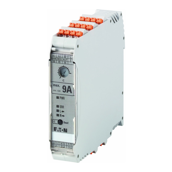
LED R (yellow) – for reversing starters or LED ON (yellow) – for direct starters i Set/reset button j Terminals for input voltage k Terminals for output voltage l Top-hat rail fitting EMS2… Electronic motor starter 10/19 MN034003EN www.eaton.com... -
Page 14: Motor Starter Without Safety Function (Do, Ro)
The motor starter itself also works if the current is under this minimum value. This state is displayed by the flashing of both LEDs PWR and ERR. The relay output also signals an alarm. EMS2… Electronic motor starter 10/19 MN034003EN www.eaton.com... -
Page 15: Block Diagrams
2.2 Motor starter without safety function (DO, RO) 2.2.1 Block diagrams SET/ RESET RESET Reset Figure 2: Block diagram direct starter SET/ RESET RESET Reset Figure 3: Block diagram reversing starter EMS2… Electronic motor starter 10/19 MN034003EN www.eaton.com... -
Page 16: Terminal Assignment
Relay output for fault messages Relay output for fault messages Relay output for fault messages RES / MAN Input for manual resetting of error messages RES / AUT Input for automatic resetting of error messages EMS2… Electronic motor starter 10/19 MN034003EN www.eaton.com... -
Page 17: Motor Starter With Safety Function (Dos, Ros)
The motor starter itself will also work even though the current is under the minimum value. This is indicated by both PWR and ERR LEDs flashing. The relay output also signals an alarm. EMS2… Electronic motor starter 10/19 MN034003EN www.eaton.com... -
Page 18: Block Diagrams
The voltages supplying the motor starter on terminals A1 and A2 and the voltage which activates terminals ON or R and L do not need to originate from the same source. Reference point for activation is terminal E. EMS2… Electronic motor starter 10/19 MN034003EN www.eaton.com... -
Page 19: Example Of A Reversing Starter
Relay output for fault messages Relay output for fault messages Relay output for fault messages RES / MAN Input for manual resetting of error messages RES / AUT Input for automatic resetting of error messages EMS2… Electronic motor starter 10/19 MN034003EN www.eaton.com... -
Page 20: Mounting
EMS-XBR-… (→ section 9.1.1, “Three-phase current connec- tor”, page 53) three-phase current connectors can be used to connect the supply terminals 1L1, 3L2 and 5L3 of up to 5 devices in a row. EMS2… Electronic motor starter 10/19 MN034003EN www.eaton.com... -
Page 21: Layout Of Devices With I E = 9 A
Contact the motor manufacturer to establish the actual value. EMS2 devices with a rated operational current I of 2.4 A or 3 A can be operated at temperatures up to 60 °C without restriction. EMS2… Electronic motor starter 10/19 MN034003EN www.eaton.com... - Page 22 20 mm: 6.5 A > 4.7 A → permissible! • Conclusion: The EMS2 motor starter can be used for this application, but must be mounted with a distance of at least 20 mm between the devices. EMS2… Electronic motor starter 10/19 MN034003EN www.eaton.com...
-
Page 23: Plug-In Motor Starter Rosf For Mounting On An Adapter
3 Plug-in motor starter ROSF for mounting on an adapter 3 Plug-in motor starter ROSF for mounting on an adapter Plug-in motor starters of the EMS2 series are available exclusively as reversing starters with a safety function (EMS2-ROSF-…). → The motor starters described in this Section must not be oper- ated in potentially explosive Exe increased safety (ATEX) areas. - Page 24 A2 and the voltage which activates terminals R and L do not need to originate from the same source. Reference point for activation is terminal E. Figure 10:Mutual (left) and separate (right) voltage sources for supply and control inputs EMS2… Electronic motor starter 10/19 MN034003EN www.eaton.com...
-
Page 25: Mounting
In addition, EMS2-ROSF motor starters are compatible with the Motor Starter Feeder System (MSFS). → Note that a direct linking of devices with a rated operational current I of 9 A can lead to a reduction in performance (derating) under some circumstances. EMS2… Electronic motor starter 10/19 MN034003EN www.eaton.com... -
Page 26: Layout Of Devices With Adapter Ems2-Xth
The maximum current during start-up of the motor is derived by multiplying the motor rated current with the “startup factor”, which with standard asyn- chronous motors is usually between 6 and 10. Contact the motor manufacturer to establish the actual value. EMS2… Electronic motor starter 10/19 MN034003EN www.eaton.com... - Page 27 20 mm distance: 6.7 A > 4.7 A → permissible! • Conclusion: The motor starter EMS2 can be used for this application; it must, however, be mounted with at least 20 mm distance between the next device. EMS2… Electronic motor starter 10/19 MN034003EN www.eaton.com...
-
Page 28: Layout Of Devices With Adapter Ems2-Xbb Or Msfs
= 3 A = 60 °C [°C] Figure 14: Derating curve for directly linked devices with I = 9 A = temperature of the current busbar = ambient temperature in the control panel EMS2… Electronic motor starter 10/19 MN034003EN www.eaton.com... -
Page 29: Short-Circuit / Motor Protection
Fuse 16 A FF / gR (10 x 38 mm) 10 kA 500 V Fuse 20 A FF / gR (10 x 38 mm) 5 kA 400 V Fuse 30 A CC (10 x 38 mm) 30 kA 480 V EMS2… Electronic motor starter 10/19 MN034003EN www.eaton.com... -
Page 30: Use In Ul Environment
For use with a “low voltage, limited energy, isolated power sup- ply” use copper cables approved to at least 75 °C. The device is designed for use with a “low voltage, limited energy, isolated power supply”. EMS2… Electronic motor starter 10/19 MN034003EN www.eaton.com... -
Page 31: Motor Protection
1000 Class 10 A 10 I / I Figure 16: Tripping characteristics class 10A t = tripping time I = actual motor current = setting of the motor protection on the device EMS2 EMS2… Electronic motor starter 10/19 MN034003EN www.eaton.com... -
Page 32: Symmetry Detection
A 230 V AC brake must be connected to the 4/T2 terminals and the star point of the motor. WARNING Increase motor current monitoring to the nominal brake current. This should be set accordingly on the hybrid motor starter. EMS2… Electronic motor starter 10/19 MN034003EN www.eaton.com... -
Page 33: Conditions When Setting The Motor Protection
Compare the set value with that which is displayed on the ▶ LEDs (→ table 10, page 30). or QR code Leaving parameterization mode ▶ Press the RESET button. Press > 1 sec EMS2… Electronic motor starter 10/19 MN034003EN www.eaton.com... -
Page 34: Displaying The Set Value
Setting I = 2.4 A = 3 A = 9 A (EMS2-…-2.4...) (EMS2-…-3...) (EMS2-…-9...) – 0.18 0.18 0.25 0.41 0.44 0.56 0.71 0.68 0.87 0.88 1.02 1.117 1.33 1.48 1.63 1.79 1.94 2.09 2.25 EMS2… Electronic motor starter 10/19 MN034003EN www.eaton.com... -
Page 35: Tripping And Reset
(depending on the previously driven operating direction). Reset EMS2 series motor starters have a “thermal memory”, which means that a reset after the motor protection has tripped is possible only once a waiting period (cooling-down time) has passed. - Page 36 4 Short-circuit / motor protection 4.2 Motor protection EMS2… Electronic motor starter 10/19 MN034003EN www.eaton.com...
-
Page 37: Application Examples
(→ section 5.1, “Single-channel controlled stop application (cat. 3, SIL 3, PL e) with error prevention”, page 34, → section 5.2, “Reversing starter 24 V DC with safety function (dual-channel) (cat. 3, SIL 3, PL e)”, page 36). EMS2… Electronic motor starter 10/19 MN034003EN www.eaton.com... -
Page 38: Single-Channel Controlled Stop Application (Cat. 3, Sil 3, Pl E) With Error Prevention
The mutual reference point of the control inputs (terminal E) is switched via the safety relay. The preset for the control commands for the operating direction takes place directly at 24 V DC on the L or R terminal. EMS2… Electronic motor starter 10/19 MN034003EN www.eaton.com... - Page 39 A1 and A2 is switched off by the safety relay. Please also refer to Page 33 for more information about the lifespan of devices. → Motor starter and safety relay should be located in the same control panel. EMS2… Electronic motor starter 10/19 MN034003EN www.eaton.com...
-
Page 40: Reversing Starter 24 V Dc With Safety Function (Dual-Channel) (Cat. 3, Sil 3, Pl E)
(terminal E) and the control commands L and R are switched via the safety relay. The preset for the control commands for the operating direction takes place directly at 24 V DC on the L or R terminal. EMS2… Electronic motor starter 10/19 MN034003EN www.eaton.com... - Page 41 A1 and A2 is switched off by the safety relay, which causes a reduction in the lifespan of the motor starter. Please also note the information about the lifespan of devices on Page 33. EMS2… Electronic motor starter 10/19 MN034003EN www.eaton.com...
- Page 42 5 Application examples 5.2 Reversing starter 24 V DC with safety function (dual-channel) (cat. 3, SIL 3, PL e) EMS2… Electronic motor starter 10/19 MN034003EN www.eaton.com...
-
Page 43: Status Messages
– yellow no designation – yellow ERR – red ERR – red no designation – yellow L – yellow ON – yellow R – yellow Figure 22: LEDs on direct and reversing starters EMS2… Electronic motor starter 10/19 MN034003EN www.eaton.com... - Page 44 6 Status messages 6.1 LEDs on the front of the device The status LEDs in combination provide information about the device status LED does not light up LED lights up LED flashes EMS2… Electronic motor starter 10/19 MN034003EN www.eaton.com...
- Page 45 Error has occurred during clockwise Automatic, as soon as the error has • No motor connected operation. The power circuit is still been remedied • Motor current < I for more connected. than 2 s EMS2… Electronic motor starter 10/19 MN034003EN www.eaton.com...
-
Page 46: Output Relay
It is possible to reset the device using a manual command during this period of time. The condition for this is that the cooling-down time for a manual reset (approx. 2 minutes) has passed. (One of the L, R or ON LEDs is flash- ing). EMS2… Electronic motor starter 10/19 MN034003EN www.eaton.com... -
Page 47: Manual Reset
In this case, connecting the PLC to terminal A2 could destroy the PLC. → The error is not reset when the reset signal is applied; it is reset when it is withdrawn (falling edge). EMS2… Electronic motor starter 10/19 MN034003EN www.eaton.com... - Page 48 6 Status messages 6.3 Resetting after an error message EMS2… Electronic motor starter 10/19 MN034003EN www.eaton.com...
-
Page 49: Technical Data
In a domestic environment, this device may cause radio interference, in which case the user cause radio interference, in which case the user may be required to take adequate measures. may be required to take adequate measures. EMS2… Electronic motor starter 10/19 MN034003EN www.eaton.com... - Page 50 LOW < 9.6 V DC LOW < 44 V AC HIGH > 19.2 V DC HIGH > 85 V AC Protection against polarity reversal Typical break time < 30 ms < 70 ms EMS2… Electronic motor starter 10/19 MN034003EN www.eaton.com...
- Page 51 42 V AC - 550 V AC 42 V AC - 550 V AC Rated operational current AC51 Rated operational current AC53a Permissible load current range 0.18 A - 3 A 1.5 A - 9 A EMS2… Electronic motor starter 10/19 MN034003EN www.eaton.com...
- Page 52 4.2 FIT at 40 °C ambient temperature – failures (du = dangerous, undetectable) SFF (Safe Failure Fraction) 99.8 % at 40 °C ambient temperature – DC (Diagnostic Coverage) 99.4 % at 40 °C ambient temperature – EMS2… Electronic motor starter 10/19 MN034003EN www.eaton.com...
- Page 53 (6 months / 36 months) at 40 °C ambient temperature: – (Average Probability of Failure on Demand) 6 months: 1,97487 x 10 36 months: 12,1362 x 10 Safety level according to IEC 61508-1: SIL 2 – EMS2… Electronic motor starter 10/19 MN034003EN www.eaton.com...
- Page 54 7 Technical data EMS2… Electronic motor starter 10/19 MN034003EN www.eaton.com...
-
Page 55: Dimensions
Figure 25: EMS2-DO-Z-…, EMS2-RO-Z-…, EMS2-DOS-Z-…, EMS2-ROS-Z-… 8.1.2 Motor starters with push-in terminals for top-hat rail mounting • EMS2-DO-T-… • EMS2-RO-T-… • EMS2-DOS-T-… • EMS2-ROS-T-… 22.5 mm 113.6 mm (4.47") (0.89") Figure 26: EMS2-DO-T-…, EMS2-RO-T-…, EMS2-DOS-T-…, EMS2-ROS-T-… EMS2… Electronic motor starter 10/19 MN034003EN www.eaton.com... -
Page 56: Plug-In Motor Starters
EMS2-ROSF-… 22.5 mm 114 mm (4.49") (0.89") 125 mm (4.92") Figure 27: EMS2-ROSF-… 8.2 Adapters 22.5 mm 34 mm 41.5 mm 22.5 mm (0.89") (1.34") (1.63") (0.89") Figure 28: EMS2-XTH Figure 29: EMS2-XBB60 EMS2… Electronic motor starter 10/19 MN034003EN www.eaton.com... -
Page 57: Accessories
22.5 mm from one another. The length l of the connection cable is 3 m. Figure 30: Three-phase current connector EMS2… Electronic motor starter 10/19 MN034003EN www.eaton.com... - Page 58 22.5 mm screw terminals EMS2-XBR-Z-3 22.5 mm EMS2-XBR-Z-4 22.5 mm EMS2-XBR-Z-5 22.5 mm EMS2-XBR-T-2 for devices with 22.5 mm push-in terminals EMS2-XBR-T-3 22.5 mm EMS2-XBR-T-4 22.5 mm EMS2-XBR-T-5 22.5 mm EMS2… Electronic motor starter 10/19 MN034003EN www.eaton.com...
-
Page 59: Control Current Connector
10 x 38 mm 20A /690V (CC) / Superflink gR EMS2-ROSF-Z-9-24VDC 3x 10x38-30A-GR 10 x 38 mm 30A /690V (CC) / Superflink gR 1) We recommended using fuses manufactured by Mersen or fuses with similar characteristics EMS2… Electronic motor starter 10/19 MN034003EN www.eaton.com... - Page 60 9 Accessories 9.2 Fuses EMS2… Electronic motor starter 10/19 MN034003EN www.eaton.com...
-
Page 61: Index
....... . 21 MSFS (Motor Starter Feeder System) ..21 EMS2… Electronic motor starter 10/19 MN034003EN www.eaton.com...
Need help?
Do you have a question about the EMS2 Series and is the answer not in the manual?
Questions and answers