
Subscribe to Our Youtube Channel
Related Manuals for Fuji Electric Micro-Controller X Socket type


Summary of Contents for Fuji Electric Micro-Controller X Socket type
- Page 1 Digital temperature controller Micro-Controller X Socket type Type: PXF4 Operation Manual INP-TN5A4117-E...
-
Page 3: Safety Instructions
Safety Instructions Please read the safety instructions throughly before using the equipment. The safety instructions must be observed by every user to prevent accidents. Failure to comply with the instructions contained in this manual may reduce the safety of the equipment. The safety instructions are classified into “Warning”... -
Page 4: Warning
WARNING Installation and wiring This equipment is intended to be used under the following conditions. ● Ambient temperature -10 to 50°C 90%RH or less (Non condensation) Operating humidity Installation category According to IEC 61010-1 Pollution degree Recommended fuse 250 V AC, 0.1 A, T (Time-Lag) (100 to 240 V AC), 400 V DC/AC, 1 A, T (Time-Lag) (24 V DC/AC) Usage environment Indoor use... -
Page 5: Maintenance
If the voltage exceeds 50 V DC (which is called as hazardous voltage), install a basic insulation between all ● terminals and the ground, and supplementary insulation on the digital outputs. Note that the insulation class for this equipment is as follows. Before installing, please confirm that the insulation class for equipment meets usage requirements. -
Page 6: Caution
Caution Installation Please avoid installing in the following locations. ● • Locations in which the ambient temperature falls outside the range of –10 to 50 °C when equipment is in use. • Locations with rapid temperature changes, leading to dew condensation •... -
Page 7: Wiring
Do not block the air vents on the top and bottom of the case. ● Wiring For thermocouple input, use the designated compensation lead; for RTD input, use wires with small lead wire ● resistance and without any resistance difference among the three wires. To avoid noise conductor effects, input signal wires should be separated from electric power lines or load lines. -
Page 8: Table Of Contents
Contents Safety Instructions ........................1 WARNING ..............................2 Installation and wiring ..........................2 Maintenance ............................3 Caution ..............................4 Installation............................... 4 Panel mounting ............................4 Wiring ..............................5 Operation ..............................5 Others ..............................5 For Proper Use ........................8 Model Specifications........................ 9 Part names and functions .................... - Page 9 3-2 2nd block parameter ..........................30 [P] Proportional band (030) ........................30 [i] Integral time (031) ..........................30 [d] Derivative time (032) ........................30 [HyS] Hysteresis range for ON/OFF control (033) ..................32 [bAL] Output convergence value (036) ....................34 [AR] Anti-reset windup (037) ........................
-
Page 10: For Proper Use
For Proper Use Confirmation of model Please confirm that the model delivered matches your order. code “Model Specifications” (see page 9) Installation and Mounting External dimensions • Panel cutout • Panel mounting dimensions “4 Installation and Mounting” (instruction manual) Wiring Terminal connection diagram “5 Wiring”... -
Page 11: Model Specifications
Model Specifications 4 5 6 7 8 9 10 11 12 13 Digit Specification Note <Front panel size W×H> 48×48mm <Input signal> Universal input Universal input (PXV/PXW/PXZ) Note 1 <Control output> Relay contact (SPDT) SSR drive output Current output <Terminal form> Socket type <Revision code>... -
Page 12: Part Names And Functions
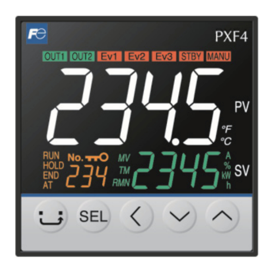
Part names and functions This section describes the names and functions of each part of the front panel. The front panel has the PV and SV displays, the status indicator lamps, and the setting keys, etc. Their functions are explained below. Please read and understand them before using the PXF. -
Page 13: 1-2 Indicators
Indicators 1-2 Indicators (1) Process variable (PV) Indicates the process variable. In the parameter setup mode, the parameter name is displayed. (2) OUT1 indicator Lights during control output is ON. (3) EV1, EV2 indicators Lights during digital output 1 to 2 are ON. (4) STBY indicator Lights when the stanby is set to ON. -
Page 14: 1-3 Digital Characters
Part names and functions 1-3 Digital characters The following tables provide correspondence between digital characters used for the display of the controller and alphanumerical characters. (See the following table for details.) Digital character Alphabet Digital character Numer ― ―... -
Page 15: Basic Operation
Basic Operation 2-1 Basic operation The below figure illustrates the mode transition and the key operations. Power ON Operation Mode To switch between SV and MV Press To change the setpoint ● Press to change the value. ● Press to move to the next digit. ●... -
Page 16: Changing Sv (Set Value)
Basic Operation 2-2 Changing SV (Set value) [Description] ––––––––––––––––––––––––––––––––––––––––––––––––––––––– The SV is a target value for control. SV must be within the range between [ SV-L] (lower limit) and [SV-H] (upper limit) which belong to Pid ● parameter. Related parameters: SV (Set value) lower limiter [SV-L], SV (Set value) upper limiter [SV-H] (see page 58) ●... -
Page 17: 2-3 Parameters List
Parameters List 2-3 Parameters List The following explains each channel parameter. The range of the parameters in the shaded area indicates the industrial values. ● When you change the PV input lower limit (P-SL), PV input upper limit (P-SU), or decimal place position (P-dP), reconfigure all the industrial values. -
Page 18: 2Nd Block Parameter
Basic Operation 2nd block parameter Factory Parameter Parameter Reference Parameter name Setting range No Display symbol default setting mask DSP page Proportional band 0.0 to 999.0 (%) DSP3-2 Integral time 0 to 3200 (sec) DSP3-4 Derivative time 0.0 to 999.9 (sec) 60.0 DSP3-8 Hysteresis range for ON/... - Page 19 Parameters List Factory Parameter Parameter Reference Parameter name Setting range No Display symbol default setting mask DSP page SV lower limit (SV-L) to SV-1 1st target SV 0 (°C) DSP6-8 SV upper limit (SV-H) %FS tM1R 1st ramp time 0.00 to 99.59 0:00 DSP6-16 tM1S...
-
Page 20: 3Rd Block Parameter
Basic Operation 3rd block parameter Factory Parameter Parameter Reference Parameter name Setting range No Display symbol default setting mask DSP page P-N1 Control action 0 to 3 DSP9-16 SV-L SV (Set value) lower limiter 0 to 100%FS 0 (°C) DSP9-32 SV-H SV (Set value) upper limiter 0 to 100%FS... -
Page 21: Temperature Control Functions
Temperature control functions 2-4 Temperature control functions This controller has five types of temperature control function. Select according to type and use. Temperature control Description functions Switches output control ON/OFF according to the SV/PV magnitude relationship. ON/OFF (2-position) Control systems can be built from simple elements such as SSR. This is appropriate control for situations where high accuracy is not required. -
Page 22: Parameter Functions And Setting Procedure
Parameter functions and setting procedure 3-1 1st block parameter MANU Manual mode selection (001) [Description] ––––––––––––––––––––––––––––––––––––––––––––––––––––––– Allows you to select how to set the manipulated variable, automatically or manually. Setpoint Description Automatically Manually MANU indicator lights during manual operation. (see page 11) ●... -
Page 23: [Stby] Standby Setting (002)
1st block parameter Stby Standby setting (002) [Description] ––––––––––––––––––––––––––––––––––––––––––––––––––––––– Allows you to switch between run and standby. Setpoint Description Operation mode Standby mode STBY indicator lights during stanby. (see page 11) ● When hold alarms is on, the hold function activates when you switch the standby setting from “ oN ” to “ oFF .” ●... -
Page 24: [Prog] Ramp Soak Control (004)
Parameter functions and setting procedure PRoG Ramp soak control (004) [Description] ––––––––––––––––––––––––––––––––––––––––––––––––––––––– Allows you to switch between Ramp soak states. Setpoint Description Ramp soak is stopped. Ramp soak starts. Ramp soak hold. To release the hold, select “ RUN ” again. This function automatically changes the SV (Set value) according to the program pattern set in advance as shown ●... - Page 25 1st block parameter [Setting example] Starting the ramp soak program –––––––––––––––––––––––– Display Operating procedure Press and hold the key for about one second during the SV/PV display. appears. ➔ ➔ Press the key to display Press the key. ➔ The setpoint starts blinking. ➔...
-
Page 26: [Lach] Alarm Latch Cancel (005)
Parameter functions and setting procedure LACH Alarm latch cancel (005) [Description] ––––––––––––––––––––––––––––––––––––––––––––––––––––––– Allows you to cancel the alarm latch. Setpoint Description keeps the latch on releases latch [Setting example] Unlatching the alarm ––––––––––––––––––––––––––––––––– Display Operating procedure Press and hold the key for about one second during the SV/PV display. -
Page 27: [At] Auto-Tuning (006)
1st block parameter Auto-tuning (006) [Description] ––––––––––––––––––––––––––––––––––––––––––––––––––––––– Running auto-tuning automatically sets the optimal PID. Setpoint Description Stops or finishes the auto-tuning. Starts the normal auto-tuning. L-oN Starts the low-PV auto-tuning. There are the following two types in auto-tuning. ● Normal type AT start Process AT calculating... - Page 28 Parameter functions and setting procedure [Setting example] Running Auto-tuning ––––––––––––––––––––––––––––––––– Display Operating procedure Press and hold the key for about one second during the SV/PV display. appears. ➔ ➔ Press the key to display Press the key. ➔ The setpoint starts blinking. ➔...
-
Page 29: [Tm1] [Tm2] Timer 1 Display (007), Timer 2 Display (008)
1st block parameter Timer 1 display (007), Timer 2 display (008) [Description] ––––––––––––––––––––––––––––––––––––––––––––––––––––––– Displays the remaining time of the timer 1 and the timer 2. The remaining time of the ON/OFF-delay timer is counted down. When the counter shows “ 0 ,” the alarm relay ●... -
Page 30: [Al1] [A1-L] [A1-H] Alarm 1 Settings (010 , 011, 012)
Parameter functions and setting procedure A1-H Alarm 1 settings (010, 011, 012) A1-L A2-H Alarm 2 settings (013, 014, 015) A2-L [Description] ––––––––––––––––––––––––––––––––––––––––––––––––––––––– Allows you to set the alarm setpoint. AL1, AL2: Alarm ● A1-L, A2-L: Low-limit alarm ● A1-H, A2-H: High-limit alarm ●... -
Page 31: [Loc] Key Lock (019)
1st block parameter LoC Key lock (019) [Description] ––––––––––––––––––––––––––––––––––––––––––––––––––––––– Prevents SV parameters from being changed. Description Setpoint Unlocked (reset) All settings are unchangeable from the controller, but changeable via communication. Only the SV is changeable from the controller, and all settings are changeable via communication. All settings are changeable from the controller, but unchangeable via communication. -
Page 32: 2Nd Block Parameter
Parameter functions and setting procedure 3-2 2nd block parameter Proportional band (030) Integral time (031) Derivative time (032) [Description] ––––––––––––––––––––––––––––––––––––––––––––––––––––––– Allows you to set PID (Proportional Band, Integration Time, Differential Time). Setting range P: 0.0 to 999.9% i: 0 to 3200 seconds d: 0.0 to 999.9 seconds The following control methods are available with PID settings. - Page 33 2nd block parameter [Setting example] Setting P = 10.0%, I = 100sec, D = 20sec ––––––––––––––––– Display Operating procedure Press and hold the key for about three seconds during the SV/PV display. ➔ appears. ➔ Press the key. ➔ The setpoint starts blinking. ➔...
-
Page 34: [Hys] Hysteresis Range For On/Off Control (033)
Parameter functions and setting procedure HyS Hysteresis range for ON/OFF control (033) [Description] ––––––––––––––––––––––––––––––––––––––––––––––––––––––– If you set the control method parameter [CtRL] to “ oNoF ,” set the hysteresis for on/off control in this parameter. Setting range 0 to 50%FS The controllability varies with the size of the hysteresis. - Page 35 2nd block parameter [Setting example] Changing the hysteresis range from 25%FS to 30%FS –––––– Display Operating procedure Press and hold the key for about three seconds during the SV/PV display. ➔ appears. ➔ Press the key to display Press the key.
-
Page 36: [Bal] Output Convergence Value (036)
Parameter functions and setting procedure bAL Output convergence value (036) [Description] ––––––––––––––––––––––––––––––––––––––––––––––––––––––– Output convergence value is a function that adds an offset to MV value. Setting range -100 to 100% By this function, the [bAL] offset is added to original MV which is the result of PID calculation determined by ●... -
Page 37: [Ar] Anti-Reset Windup (037)
2nd block parameter Anti-reset windup (037) [Description] ––––––––––––––––––––––––––––––––––––––––––––––––––––––– Anti-reset windup is a function that limits the range of valid integration to control overshooting. Setting range 0 to 100%FS The anti-reset windup function ([AR]) disables the integration when the PV falls outside of the Ar set range that ●... -
Page 38: [Ctrl] Control Algorithm (038)
Parameter functions and setting procedure CtRL Control algorithm (038) [Description] ––––––––––––––––––––––––––––––––––––––––––––––––––––––– This controller has five temperature control functions. Select the best control method for your application. Setpoint Description oNoF ON/OFF (2-position) control PID control FUZY Fuzzy control SELF Self tuning control Pid2 PID2 control (1) ON/OFF (2-position) control (oNoF) - Page 39 2nd block parameter (2) PID control (Pid) PID control starts when the parameter [CtRL] is “ Pid.” PID control calculate Pid and output the result according to the set values of the parameters [P], [i], [d], and [AR]. (-5 to 105%) Each parameter can be set either by manually tuning the values or by running auto-tuning ([AT]) to automatically set the values.
- Page 40 Parameter functions and setting procedure (5) PID2 control (Pid2) This type of control reduces overshoot during control for processes that turn the control target off and then on again. Set value Suppresses overshoot Controller power Close Close Control loop Open The algorithm used prevents over-integration of the PID calculations even while the control loop is still open.
-
Page 41: [Slfb] Pv (Process Variable) Stable Range (039)
2nd block parameter SLFb PV (Process variable) stable range (039) [Description] ––––––––––––––––––––––––––––––––––––––––––––––––––––––– Self-tuning logic recognizes that control is stable if PV is staying within the SV ± [SLFb]. Setting range 0 to 100%FS It is not necessary to set this parameter under normal conditions. ●... -
Page 42: [Onof] Hysteresis Mode (040)
Parameter functions and setting procedure oNoF Hysteresis mode (040) [Description] ––––––––––––––––––––––––––––––––––––––––––––––––––––––– Selects the hysteresis operation during two-position control. Description Setpoint Performs two-position control with the range between [SV+HyS/2] and [SV-HyS/2]. Performs two-position control with the range between [SV, SV+HyS] and [SV, SV-HyS]. Setpoint: oFF Setpoint: oN Reverse... -
Page 43: [Tc] Cycle Time Of Control Output 1 (041)
2nd block parameter Cycle time of control output 1 (041) [Description] ––––––––––––––––––––––––––––––––––––––––––––––––––––––– Output ON When using contact output and SSR drive output with PV input inside the proportional band, output will switch between ON and OFF at regular intervals. Setting range Proportional cycle 1 to 150 sec... -
Page 44: [P-N2] Input Signal Code (043)
Parameter functions and setting procedure P-N2 Input signal code (043) [Description] ––––––––––––––––––––––––––––––––––––––––––––––––––––––– Allows you to select PV input source from thermocouples, RTD, and others. Setpoint Description Setpoint Description RTD JPt100 Thermocouple N RTD Pt100 Thermocouple PL-II PL-2 Thermocouple J Thermocouple W Thermocouple K 0-5V 0 to 5 V DC... -
Page 45: [P-Sl] Lower Limit Of Measuring Range (044)
2nd block parameter P-SL Lower limit of measuring range (044) P-SU Upper limit of measuring range (045) [Description] ––––––––––––––––––––––––––––––––––––––––––––––––––––––– Allows you to set the upper/lower limit of PV input within the PV input 1200℃ measurement range. 1000℃ Setting range Scaling range -1999 to 9999 upper/lower limit 200℃... - Page 46 Parameter functions and setting procedure [Setting example] Setting the PV input upper limit to 1000°C and lower limit to 200°C –– Display Operating procedure Press and hold the key for about three seconds during the SV/PV display. ➔ appears. ➔ Press the key to display Press the...
-
Page 47: [P-Dp] Decimal Point Position (046)
2nd block parameter P-dP Decimal point position (046) [Description] ––––––––––––––––––––––––––––––––––––––––––––––––––––––– Sets the decimal point position for the PV. Setpoint Description No digit after decimal point 1 digit after decimal point One decimal place Two decimal places 2 digits after decimal point Three decimal places 3 digits after decimal point Two decimal places and three decimal places are available only when the input is voltage or current. -
Page 48: [Pvof] Pv Offset (048)
Parameter functions and setting procedure PVOF PV offset (048) [Description] ––––––––––––––––––––––––––––––––––––––––––––––––––––––– This function shifts PV input before display. PV display This function can be used to make the SV correspond with other 100°C 95°C instruments. Before shift Setting range After -10.00 to 10.00%FS shift This controller operates at the displayed PV (the value to which the PV... -
Page 49: [Svof] Sv Shift (050)
2nd block parameter SVOF SV shift (050) [Description] ––––––––––––––––––––––––––––––––––––––––––––––––––––––– This function specifies the SV shift. This is used to eliminate remaining offset when using P control. Setting range -50.00 to 50.00%FS Controls act on the calculated SV with SV offset. ●... -
Page 50: [P-Df] Time Constant Of Input Filter (050)
Parameter functions and setting procedure P-dF Time constant of input filter (050) [Description] ––––––––––––––––––––––––––––––––––––––––––––––––––––––– This low-pass filter function reduces noise and signal Control Input fluctuation. output filter Setting range 0.0 to 120.0 sec If the input filter time constant is set to 5 and input is changed ●... -
Page 51: [Alm1] [Alm2] Alarm Type 1, 2 (051, 052)
2nd block parameter ALM1 ALM2 Alarm type 1, 2 (051, 052) [Description] ––––––––––––––––––––––––––––––––––––––––––––––––––––––– Set the alarm type for Alarm1, Alarm2. 1-point alarm 2-point alarm Type Setpoint Alarm type Action diagram Type Setpoint Alarm type Action diagram No alarm ― An-H High/Low absolute alarm An-L High alarm... - Page 52 Parameter functions and setting procedure When alarm action code is changed, alarm set value may also become different ● from previous settings. Power-cycle the controller after you change the alarm type. ● [Setting example] Setting the type of the alarm 1 to “upper limit deviation alarm with hold” –––––––– Display Operating procedure Press and hold the...
-
Page 53: [Stat] Status Display Of Ramp Soak (054)
2nd block parameter StAt Status display of ramp soak (054) [Description] ––––––––––––––––––––––––––––––––––––––––––––––––––––––– Displays the progress of the ramp soak. The ramp soak statuses are indicated as follows. Display Status Ramp soak is stopped 1-RP Step 1 ramp 1-St Step 1 soak 2-RP Step 2 ramp 2-St... -
Page 54: [Ptn] Ramp Soak Execution Pattern (055)
Parameter functions and setting procedure Ramp soak execution pattern (055) [Description] ––––––––––––––––––––––––––––––––––––––––––––––––––––––– The 8-step ramp soak patterns are divided into 3 segments. You can choose any one to use. Description Setpoint SV-3 Steps 1 to 4 SV-8 SV-6 SV-2 Steps 5 to 8 SV-4 SV-1 Steps 1 to 8... -
Page 55: [Sv-1] To [Sv-8] 1St Target Sv To 8Th Target Sv (056 To 077)
2nd block parameter SV-1 to SV-8 1st target SV to 8th target SV (056 to 077) tM1R to tM8R 1st ramp time to 8th ramp time (057 to 078) tM1S to tM8S 1st soak time to 8th soak time (058 to 079) [Description] –––––––––––––––––––––––––––––––––––––––––––––––––––––––... - Page 56 Parameter functions and setting procedure [Setting example] Setting SV1, ramp time, and soak time for step1 ––––––––––– Display Operating procedure Press and hold the key for about three seconds during the SV/PV display. ➔ appears. ➔ Press the key to display Press the key.
-
Page 57: [Mod] Ramp Soak Mode (080)
2nd block parameter Mod Ramp soak mode (080) [Description] ––––––––––––––––––––––––––––––––––––––––––––––––––––––– Allows you to set the method of ramp soak operation. You can select from 16 options that are the combinations of the following four items. ● Starts ramp soak with the current PV when the PXF is turned on. Power-on start Maintains the same state as at the end of ramp soak when ramp soak is complete. - Page 58 Parameter functions and setting procedure [Setting example] Setting the ramp soak mode to 1 –––––––––––––––––––––––– Display Operating procedure Press and hold the key for about three seconds during the SV/PV display. ➔ appears. ➔ Press the key to display Press the key.
-
Page 59: 3Rd Block Parameter
3rd block parameter 3-3 3rd block parameter P-N1 Control action (090) [Description] ––––––––––––––––––––––––––––––––––––––––––––––––––––––– This parameter specifies the control action and the output when an event occurs. Control action Burn-out output* Setpoint Lower limit Reverse Upper limit Lower limit Direct Upper limit * The output during burnout is as follows. -
Page 60: [Sv-L] Sv (Set Value) Lower Limiter (091)
Parameter functions and setting procedure SV-L SV (Set value) lower limiter (091) SV-H SV (Set value) upper limiter (092) [Description] ––––––––––––––––––––––––––––––––––––––––––––––––––––––– Process Variable These parameters specify the setting range of the SV. You can set PV input any value within the measurement range. upper limit SV upper limit Setting range... -
Page 61: Dly1 Dly2 Delay Time 1, 2 (093, 094)
3rd block parameter dLY2 Delay time 1, 2 (093, 094) dLY1 A2Hy Alarm 1, 2 hysteresis (098, 099) A1Hy [Description] ––––––––––––––––––––––––––––––––––––––––––––––––––––––– Parameter Description Setting range Specifies the amount of time from the occurrence of the alarm to dLY1, dLY2 0 to 9999 (sec) the sounding of the alarm A1Hy, A2Hy Specifies alarm detection width and recovery width. - Page 62 Parameter functions and setting procedure Display Operating procedure Press the key to display Press the key. ➔ The setpoint starts blinking. ➔ Press the keys to change “ 1 ” to “ 5 .” Press the key or wait for three seconds to save the change. Press the key.
-
Page 63: A1Op A2Op Alarm 1, 2 Options (101, 102)
3rd block parameter A2oP Alarm 1, 2 options (101, 102) A1oP [Description] ––––––––––––––––––––––––––––––––––––––––––––––––––––––– You can set the optional functions to the alarm 1 and the alarm 2, if you need. The three types of optional functions are assigned for each bit. bit0 bit1 bit2... -
Page 64: [Plc1] [Phc1] Out1 Upper/Lower Limits (104, 105)
Parameter functions and setting procedure PHC1 OUT1 Upper/Lower Limits (104, 105) PLC1 [Description] ––––––––––––––––––––––––––––––––––––––––––––––––––––––– This parameter specifies the upper and lower limits for output control. 100 (%) Parameter Setting range Lower limit Upper limit PLC1 PHC1 -5.0 to 105.0 (%) 100 (%) Input Related parameters: Output limit types [PCUt] (see page 63) -
Page 65: [Pcut] Output Limit Types (108)
3rd block parameter PCUt Output limit types (108) [Description] ––––––––––––––––––––––––––––––––––––––––––––––––––––––– You can choose whether to apply the limit on the output value or let it exceed the limit. Setpoint Lower limit Upper limit 105% limit 105% limit limit limit The output changes according to the limit, as follows. ●... -
Page 66: [Out1] Output Value (Mv) Display (109)
Parameter functions and setting procedure oUt1 Output value (MV) display (109) [Description] ––––––––––––––––––––––––––––––––––––––––––––––––––––––– Displays the output value (OUT1). [Setting example] Checking the output value (OUT1) –––––––––––––––––––––– Display Operating procedure Press and hold the key for about five seconds during the SV/PV display. appears. -
Page 67: [Rcj] Rcj (Cold Junction Compensation) Setting (111)
3rd block parameter RCJ RCJ (Cold junction compensation) setting (111) [Description] ––––––––––––––––––––––––––––––––––––––––––––––––––––––– This is the procedure for turning the cold junction compensation on or off when using the input from a thermocouple sensor. Description Setpoint Cold junction compensation on Cold junction compensation off This setting should be left “... -
Page 68: [Adj0] User-Definable Zero Adjustment (113)
Parameter functions and setting procedure AdJ0 User-definable zero adjustment (113) AdJS User-definable span adjustment (114) [Description] ––––––––––––––––––––––––––––––––––––––––––––––––––––––– PV display This is the procedure for adjusting the zero point and the span for Span Setting range adjustment -50 to 50%FS Set the following equipment before using these parameters or ●... - Page 69 3rd block parameter Display Operating procedure Press the key. ➔ The setpoint starts blinking. ➔ Press the key to change “ 0 ” to “ -4 .” Press the key or wait for three seconds to save the change. Press the key.
-
Page 70: Dsp1 To Dp14 Parameter Mask (126 To 139)
Parameter functions and setting procedure dSP1 to dP14 Parameter mask (126 to 139) [Description] ––––––––––––––––––––––––––––––––––––––––––––––––––––––– The parameter mask allows you to hide unused parameters or to skip over the parameters you want to keep their setpoints. Do not let the parameters which are not described in this operation manual appear on the screen. - Page 71 3rd block parameter [Setting example] Hiding the integral time [i] and the derivative time [d] –––––––– <Preparations> Check the mask DSP of the parameter(s) you want to hide. ● (the mask DSP of the integral time [i] is “dSP3-4,” the mask DSP of the derivative time [d] is “dSP3-4.” If you want to hide multiple parameters of the same code, calculate the hexadecimal number of the ●...
-
Page 72: [Uky1] [Uky2] [Uky3] User Key Assignment (143, 144, 145)
Parameter functions and setting procedure UKy3 USER key assignment (143, 144, 145) UKy1 UKy2 [Description] ––––––––––––––––––––––––––––––––––––––––––––––––––––––– Allows you to assign a function to the (USER) key. Setting Parameter Key assignment range UKy1 (USER) key UKy2 (USER) key and 0 to 6 UKy3 (USER) key and Select a function from the table below. -
Page 73: [Flo1] Mv1 During Falt (146)
3rd block parameter FLo1 MV1 during FALT (146) [Description] ––––––––––––––––––––––––––––––––––––––––––––––––––––––– Allows you to specify the control output value when the controller falls into FALT (input error). Setting range -5.0 to 105.0% [Setting example] Setting the OUT1 during FALT to 5% ––––––––––––––––––––– Display Operating procedure Press and hold the... -
Page 74: [Dspt] Pv/Sv Display Off (148)
Parameter functions and setting procedure dSPt PV/SV display OFF (148) [Description] ––––––––––––––––––––––––––––––––––––––––––––––––––––––– This parameter is used to manually turn off the PV, SV, and LED lamps on PV/SV screen. Setpoint Function PV, SV, and LED lamps stay ON SV display OFF PV display OFF PV and SV displays OFF PV, SV, and LED lamps OFF (all off) -
Page 75: Troubleshooting
Troubleshooting When a trouble occurs, first check the model, wiring, and parameter settings. The following table shows some typical cases and their solutions. Reference Symptoms Causes Remedies pages Parameters you want Display mask is set. Check the DSP settings. Page 68 to view do not appear The ramp soak settings have the Check the ramp soak settings. - Page 76 Troubleshooting Reference Symptoms Causes Remedies pages The value of [P-SU] is set to 3277°C Set the parameters of [P-SL] and [P-SU] Page 43 “Err” has been displayed. or more for thermocouple and again according to the input range table. resistance bulb input. The measured range ([P-SU] to [P-SL]) Set the parameters of [P-SL] and [P-SU] Page 43...
- Page 77 3rd block parameter Reference Symptoms Causes Remedies pages Input filter constant is too large. Decrease the set value of the Page 48 Response is too slow. Output changes parameter of [P-dF]. between ON and OFF, Some input terminals are short- Remove the short-circuited terminals.
- Page 80 Gate City Ohsaki, East Tower, 11-2, Osaki 1-chome, Shinagawa-ku, Tokyo 141-0032, Japan Phone: +81-3-5435-7111 www.fujielectric.com www.fujielectric.com/products/instruments/...
Need help?
Do you have a question about the Micro-Controller X Socket type and is the answer not in the manual?
Questions and answers