Advertisement
Quick Links
Advertisement

Related Manuals for Fuji Electric PXZ Series


Summary of Contents for Fuji Electric PXZ Series
- Page 1 Artisan Technology Group is your source for quality new and certified-used/pre-owned equipment SERVICE CENTER REPAIRS WE BUY USED EQUIPMENT • FAST SHIPPING AND DELIVERY Experienced engineers and technicians on staff Sell your excess, underutilized, and idle used equipment at our full-service, in-house repair center We also offer credit for buy-backs and trade-ins •...
- Page 2 Fuji Electric Co., Ltd. Instruction Manual Head Office 11-2, Osaki 1-chome, Shinagawa-ku, Tokyo, 141-0032 Japan http://www.fujielectric.co.jp Micro-controller X Fuji Electric Instruments Co., Ltd. Sales Div. International Sales Dept. Model: PXZ No.1, Fuji-machi, Hino-city, Tokyo, 191-8502 Japan Phone : +81-42-585-6201,6202 Fax : +81-42-585-6187,6189 INP-TN2PXZa-E http://www.fic-net.co.jp...
- Page 3 Read before using SAFETY PRECAUTIONS Before using this product, the user is requested to read the following precautions carefully to ensure the safety. Safety precautions must be taken by every user to prevent an accident. The safety requirements are classified into "warning" and "caution" according to the following interpretation : Suggesting that the user's mishandling can result in Warning...
- Page 4 • If the voltage shown above exceeds 50Vdc(i.e. hazardous voltage), the basic insulation is required between all terminals of this equipment and the ground, and supplementary insulation is required for the alarm output. Isolation class of this equipment is shown below. Be sure check that the isolation class of the equipment satisfies your requirements before installation.
- Page 5 Caution 2.1 Cautions on installation Avoid the following places for installation. • a place where the ambient temperature may reach beyond the range of from 0 to 50°C while in operation. • a place where the ambient humidity may reach beyond the range of from 45 to 85% RH while in operation.
- Page 6 [Proportional interval] relay output: 30 seconds or more, SSR/SSC: one second or more.] • If inductive load such as magnetic switches connected as a relay output load, it is recommended to use Z-Trap manufactured by Fuji Electric to protect a contact from switching serge and keep a longer life.
- Page 7 For normal usage <Description> <Reference items> • Confirming that product delivered Confirming type identification matches with the ordered one • Outline dimension Installation/mounting • Panel cutout dimension • Mounting method on the panel • Terminal connection diagram Wiring Turning power on •...
- Page 8 Confirming type specification Model Configuration Model Configuration 11 12 13 Contents P X Z Size of the front 48×48mm 48×96mm 72×72mm 96×96mm Input type Thermocouple [℃] Thermocouple [ F] RTD (Pt100/IEC)[℃] RTD (Pt100/IEC)[ F] 4 to 20 mA DC (with 250-Ω I/V conversion resistor) (Note 1) DC1 to 5V Control output 1 Relay contact output (reverse action)
- Page 9 Installation/mounting Outline and Panel Cutout Dimensions (Standard type) (Unit: mm) Model Outline dimensions Panel cutout dimensions When installing "n" numbers 86.7 72.5 of units: PXZ4 63 or more C○ H○ L○ ○ ○ PV/SV DATA PXZ-4 +0.5 For grouped installation Panel Note) See the note below.
- Page 10 Wiring Terminal Connection (for 100 to 240 VAC) *Voltage/ PXZ5, PXZ9 PXZ7 Current input *Voltage/ Current output, SSR/SSC Current T.C. driving output Current output, input + SSR/SSC driving output + Alarm 1 T.C. + − Control output 2 (Upper limit alarm) −...
- Page 11 Terminal Connection (for 24Vac/24VDC) Attention : In case of PX 2- # ( : Don't care, #: A or B) Not available in case of PXZ7. Warning Be sure to use the rated voltage power supply and polarity. This type can be used for 24 VAC and 24 VDC power supply only. Do not use for 100 to 240 VAC power supply.
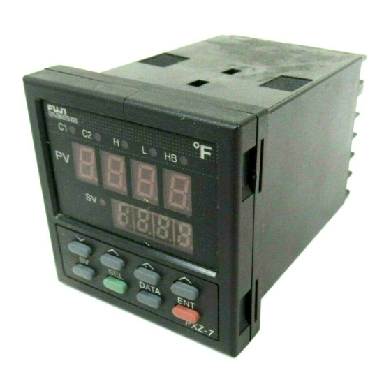
- Page 12 Usage (Read before using) Name of Functional Parts and Functions ○ ○ ○ ○ ○ C1○ C2○ H○ L○ HB○ C○ H○ L○ ○ ○ ○ ○ DATA PV/SV DATA DATA PXZ-4 PXW-7 PXW-5 Model : PXZ4 Model : PXZ5 Model : PXZ7, 9 Function Name q Measured value (PV) display Displays a measured value (PV).
- Page 13 Method of setting temperature and parameter Operating state (PV/SV indication) PXZ5, 7, 9 PXZ4 ・ SV lamp lights, indicating ・ PV lamp lights, indicating measurement value(PV) measurement value(PV). and setting value(SV). PV lamp lights SV lamp lights To change temperature setting value (SV) 1) Press key for the position to change value.
- Page 14 Parameter Description Setting range(setting unit) Reference display code oFF:Local operation ProG Ramp soak command rUn : Start of program operation HLd : Pause of program operation End : End of program operation Proportional band (ON/OFF control at 0.0) 0.0 to 999.9%FS Integral action time 0 to 3200 sec.
- Page 15 Operating state (PV/SV indication) PXZ5, 7, 9 PXZ4 ・ SV lamp lights, indicating ・ PV lamp lights, indicating measurement value(PV) measurement value(PV). and setting value(SV). PV lamp lights SV lamp lights To change temperature setting value (SV) 1) Press key for the position to change value. Light of corresponding position flashes. 2) Press keys to change value.
- Page 16 Parameter Description Setting range (Setting unit) Reference display code P-n1 Specifying control operation 0 to 19 Table 4 P-n2 Table 1 Input type setting 0 to 16 P-dF Input filter (Time constant) 0.0 to 900.0 sec. -1999 to 9999 (engineering unit) Table 2 P-SL Setting of lower limit in the range...
- Page 17 [Table 1] Input type codes Parameter: Code Group Input type Group Input type Code (P-n2) 1 to 5VDC, 4 to 20mA · Pt100 (IEC) Thermocouple · J · K · R · B · S · T * In the case of 4-20 mA DC input, use an 250-Ω outboard ·...
- Page 18 [Table 3] Alarm action type codes Parameter: ALM1 ALM2 Alarm type Action diagram ( ) ( ) No alarm Absolute High alarm value alarm Low alarm High alarm (with hold) Low alarm (with hold) Deviation High alarm alarm Low alarm High/Low alarm High alarm (with hold) Low alarm...
- Page 19 [Table 4] Control action codes Parameter: Control action Burn-out direction Code (P-n1) Output type Output 1 Output 2 Output 1 Output 2 Lower limit Reverse action Upper limit Single Lower limit Direct action Upper limit Lower limit Lower limit Upper limit Reverse action Lower limit Upper limit...
- Page 20 Useful usage of this equipment q Is the input sensor type same as what you use ? Setting Select the sensor you use from those in Table 1, and set it in the the input parameter P-n2. (Example) For T thermo-couple, set P-n2 to "7". * Skip this procedure (Note) Changing between resistance bulb and thermo-couple if specified when...
- Page 21 q Objective of control (heating or cooling applied?) Setting of Operation Method Objective Description controls scheme Set parameter P-n1 Heating Reverse Increased to 0 or 1. measurement value * Read if the control (Refer to Table 4) will decrease doesn't work as you operational output value.
- Page 22 5-1 ON/OFF (two position) control • Output ON/OFF is determined according to which of PV or SV is larger. • Set parameter P to 0 for selecting the two-position control. • Set the operation insensitive zone (hysteresis) to avoid an output chattering near PV SV.
- Page 23 5-2 Auto-tuning (AT) The auto-tuning is automatic measurement, computation, and setting of the P.I.D. constant that are performed by the micro-controller. Prior to the auto-tuning, complete the setting of input range (P-SL, P-SU, P-dP), a set value (SV), alarm setting (H,L), and proportional time cycle (TC). How to start the auto-tuning Set the parameter, AT to either “1”...
- Page 24 5-3 bAL and Ar function Note: The parameters bAL and Ar disappear at shipment. you need to set to appear below,"Switching bAL and Ar to appear or to disappear. 1) These are functions to suppress overshoot. 2) If they aren't optimum value, sometime you don't get the good control. Usually it is not necessary to set them.
- Page 25 Read if the indication is abnormal. Displays in abnormalities This unit has a display function to indicate several abnormalities. If an abnormality occurs, eliminate the cause of abnormality immediately. After the cause is eliminated, turn off the power once before the power is turned on. Display Cause Control output...
- Page 26 Specification Power voltage: 100 (- 15%) to 240 VAC (+10%), 50/60Hz or 24VDC/24 VAC (±10%), 50/60Hz Power consumption: 15VAC or less/240VAC Sensor input: Thermocouple, 3-wire resistance bulb, 1 to 5VDC Control method: PID or fuzzy PID or ON/OFF (two positions) Relay output: 1C contact, 220 VAC/30 VDC 3A (resistive load) mechanical life ;...
- Page 27 Micro controller X Type: PXZ OPERATION MANUAL PXZ-1-E Artisan Technology Group - Quality Instrumentation ... Guaranteed | (888) 88-SOURCE | www.artisantg.com...
- Page 28 Contents 1. Operating Parts and Functions....................1 2. Operation ..........................2 2-1 Parameter Table ......................2 2-2 Basic operation ....................... 4 2-3 Parameter functions and setting method ................ 5 Setting of set value (SV) ....................5 Setting of proportional band ..................6 Integral time ........................
- Page 29 Operating Parts and Functions Fig. 1-1 shows the outline of the front panel of the unit. One the front of the unit, there are PV/SV digital indication lamps, condition indication lamps and setting keys. Table 1-1 shows the functions of these oeprating parts. Before using the unit, be sure to understand the functions of the operating parts.
- Page 30 Operation The setting of set values (SV) and internal parameters of the Micro Controller X are explained in the following. 2-1 Parameter Table On Micro Controller X, parameters are classified into No. 1 and No. 2 blocks according to operation frequency. No. 1 and No. 2 blocks are used for initial setting and whenever necessary.
- Page 31 No. 2 block parameters are used for setting the initial set values, and for special operation and setting. ② No. 2 block parameter table Parameter display Initial set value User’s Parameter Name Description Page symbol prior to delivery set value mask DSP Setting of Setting of normal/reverse action of set output and burnout...
- Page 32 2-2 Basic operation ① Condition at power ON Operation Description Display PXZ4 Power ON Display at power ON is shown at right. PXZ5/7/9 ② Selection of parameter Basic operation of PXZ is shown below. When PXZ4 (1 stage display type) is used, PV/SV is displayed on the one stage display.
- Page 33 2-3 Parameter functions and setting method Setting of set value (SV) [Description] Example) Altering SV 250°C to 1195°C • Set values are control target values. Key operation Description Display • Upper/lower limit of set value is des- ignated by No. 2 block parameter Press the SEL key to display P.
- Page 34 Setting of proportional band (Setting range: 0 to 999.9% for input range) [Description] Example) Altering proportional band 10.0% to 15.0% • Proportional band can be set auto- Key operation Description Display matically by auto-tuning. • Manual setting is also possible. If Press the SEL key to display P.
- Page 35 Integral time (Setting range: 0 to 3200 sec.) [Description] Example) Altering the integrating time of 600 seconds to • Integral time can be set automati- 840 seconds cally by auto-tuning. • Manual setting is also possible. Key operation Description Display •...
- Page 36 Derivative time (Setting range: 0.0 to 999.9 seconds) [Description] Example) Altering a derivative time of 120.0 seconds to • Derivative time can be set automati- 100.0 seconds cally by auto-tuning. • Manual setting is also possible. Key operation Description Display •...
- Page 37 Lower limit alarm (ALM2) setting (option) (Setting is possible within input range) [Description] Example) Altering the lower limit alarm of 200°C to 100°C • Alarm is not displayed without Key operation Description Display lower limit alarm function. • When input or deviation is smaller Press the SEL key to display P.
- Page 38 Upper limit alarm (ALM1) setting (option) (Setting is possible within input range) [Description] Example) Altering the upper limit alarm of 300°C to • Alarm is not displayed without up- 550°C per limit alarm function. • When using upper limit alarm, it is Key operation Description Display...
- Page 39 Setting of proportional cycle of control output 1 (Setting range 1 to 150 sec.) [Description] Example) Altering a proportional cycle of 30 seconds to • When contact output or SSR drive 20 seconds output type is used, the output turns ON/OFF at a contact cycle when the Key operation Description...
- Page 40 2-position action hysteresis width (Setting range: 0.0 to 50.0%FS) [Description] Example) Altering the hysteresis width of 1°C to 2°C • Hysteresis width under the 2-posi- Key operation Description Display tion action control can be set as shown in the example. When hys- Press the SEL key to display P.
- Page 41 Heater burnout alarm (option) (Setting range: 1.0 to 50.0A) • The heater burnout alarm function • When detection error is large due to [Description] can not be used in case when the small heater capacity, increase the • Burnout detect current (parameter heater is controlled by thyristor apparent current 2 times larger by Hb) should be set according to the...
- Page 42 Example) Altering alarm setpoint of heater burnout current of 9.0A to 8.0A Key operation Description Display Press the SEL key to display P. Press the SEL key repeatedly until is displayed. Press the DATA key once. DATA Current data of 9.0A is displayed. Press the key to display 8.0.
- Page 43 Auto-tuning (Setting range: 0, 1, 2) [Description] Example) Starting auto-tuning • PID value can be set automatically. Key operation Description Display • Once PID value is set automatically by auto-tuning, it is saved in the con- Press the SEL key to display P. troller even when the power is turned OFF, so auto-tuning function is not Press the SEL key repeatedly until...
- Page 44 Cooling side proportional cycle of control output 2 (DUAL type only) (Setting range: 1 to 150 sec.) [Description] Example) Altering cooling control proportional cycle of • This setting is required only for 30 seconds to 20 seconds DUAL type. • When contact output or SSR drive Key operation Description Display...
- Page 45 Cooling side proportional band coefficient (DUAL type only) (Setting range: 0, 0.1 to 100.0) [Description] Example) Altering cooling control proportional band co- • Cooling side proportional band co- efficient of 5.0 to 5.5 efficient can be set automatically by auto-tuning. Key operation Description Display...
- Page 46 Shift of cooling side proportional band (dead band/overlap band) (DUAL type only) (Setting range: -50.0 to +50.0%) [Description] Example) Altering dead band/overlap band of 0% to 1.0% • Cooling side proportional band can (dead band) be shifted for set value (SV) (see diagram (a) below).
- Page 47 Output 1 lower limit setting (Setting range: -3.0 to 103.0%) Output 1 upper limit setting (Setting range: -3.0 to 103.0%) Output 2 lower limit setting (Setting range: -3.0 to 103.0%) Output 2 upper limit setting (Setting range: -3.0 to 103.0%) (No display prior to delivery) [Description] Example) Altering lower limit pulse width limiter from...
- Page 48 Setting of operation mode of output limiter (Setting range: 0 to 1.5) [Description] Example) Set the lower/upper limit of output 1 and out- • This function is used to set the op- put 2 to limit action eration mode of the output (1 or 2) limiter.
- Page 49 Output convergence value (Setting range: -100.0 to 100.0%) (Setting range: 0 to 100%FS) Anti-reset wind up (No display prior to delivery) [Description] Example) Altering anti-reset wind up of 80°C to 60°C • This setting is not require unless it Key operation Description Display is necessary.
- Page 50 Key lock (Setting range: 0, 1, 2) [Description] Example) Key lock to prevent accidental data change • Key lock is a function not to change Key operation Description Display set data accidentally. Parameters SV and data can be displayed. Press the SEL key to display P. •...
- Page 51 Program status display (display only) No. 1 to 4 target value 〜 No. 1 to 4 ramp time 〜 No. 1 to 4 soak time 〜 [Description] Example) Set No. 1 target value to 400°C • This is a function to change set value Key operation Description Display...
- Page 52 Setting of ramp/soak control (ProG) (option) [Description] Example) Start ramp/soak operation (rUn) from local • This function is used to change time operation (oFF) and set value (SV) automatically according to preset pattern. Up to 4 Key operation Description Display ramp/soak programs can be used.
- Page 53 Setting of control mode [Description] Example) Altering lower burnout/reverse action to upper • Used to set control mode, normal/ burnout/normal action reverse action and the direction of burnout. Key operation Description Display • Control mode is classified into the Press the SEL key for 3 seconds, and standard type (1 output) and the dual P-n1 is displayed.
- Page 54 Input filter constant (Setting range: 0.0 to 900.0 sec.) [Description] Example) Altering filter constant 5.0 (5 seconds) to 10.0 • Input filter function is used to reduce (10 seconds) noise contained in input signal. In- put filter constant is time constant. Key operation Description Display...
- Page 55 Setting of input type [Description] • On the Type II, when selecting volt- • Input type and code age input or current input, it becomes ① Input type code table • Input type can be set. necessary to change the code and •...
- Page 56 Alarm hysteresis width (option) (Setting range: 0 to 50%FS) [Description] Example) Altering alarm hysteresis 1°C to 3°C • Alarm is 2-position action, ON and Key operation Description Display OFF, while hysteresis is the differ- ence in input ON and OFF. For ex- Press the SEL key for 3 seconds, ample, when hysteresis is 5°C, the and P-n1 is displayed.
- Page 57 Lower limit of measurement range and set value (SV) (Setting range: -1999 to 9999) Upper limit of measurement range and set value (SV) (Setting range: -1999 to 9999) [Description] Example) Altering the measuring range of 0 〜 150°C to • Lower limit (minimum range) and -100 〜...
- Page 58 Setting of lower limit alarm (ALM2) action type (option) Setting of upper limit alarm (ALM1) action type (option) [Description] Absolute value alarm Lower limit hold When alarm is outputted at tempera- At the start of operation, the furnace • Alarm action can be selected from ture of more than 200°C and less than temperature is normally below 100°C.
- Page 59 Example) Altering upper limit alarm (ALM1) action from upper limit deviation alarm to upper limit ab- solute value alarm Key operation Description Display Press the SEL key for 3 seconds, and P-n1 is displayed. Press the SEL key repeatedly until P-AH is displayed.
- Page 60 Setting of RCJ compensation [Description] Example) Altering cold junction compensation from ON • This function is used whether or not to OFF RCJ compensation (cold contact compensation) is used for thermo- Key operation Description Display couple input. Normally, it should be used at ON (RCJ compensation) Press the SEL key for 3 seconds, which has been set prior to delivery...
- Page 61 Setting of decimal point position (Setting range: 0 to 2) [Description] Example) Altering the measuring range 0〜150°C to 0.0 • Decimal point position can be set on 〜 150°C LED display. Key operation Description Display → “0” Below decimal point Press the SEL key for 3 seconds, and P-n1 is displayed.
- Page 62 PV offset (Setting range: -10 to 10%FS) [Description] Example) Set the zero shift width of 5°C to input value • Set value is added to designated in- 1200°C put value. It is mainly used when recorder needs to conform with the Key operation Description Display...
- Page 63 SV offset (Setting range: -50 to 50%FS) [Description] Example) Set the zero shift width of 9°C to current set- • The value set in SV offset is added ting value. to original SV to perform control by SV value. It is mainly used to elimi- Key operation Description Display...
- Page 64 Selection of measurement input °C/°F [Description] Example) Altering the unit of measurement input from • The unit (°C or °F) of temperature °C to °F can be selected for temperature in- put. It has been set according to the Key operation Description Display ordering specifications prior to de-...
- Page 65 FUZY control setting [Description] Example) Set FUZY control to ON. • This function is used to select or not Key operation Description Display to select FUZY control. • FUZY control provides the follow- Press the SEL key for 3 seconds, ing advantages.
- Page 66 User’s adjust zero adjustment (Setting range: -50 to 50%FS) User’s adjust span adjustment (Setting range: -50 to 50%FS) [Description] Example) Set zero adjustment to +1°C • This function is used to calibrate Key operation Description Display input by user. • Using zero input or span input, er- Press the SEL key for 3 seconds, ror is set in the input range.
- Page 67 Skipping of parameter display [Description] Example) Skip I and D • This parameter is used to skip pa- Set 4 + 8 = 12 according to dSP1 code table. rameter display for each item. • This function can be used to prevent Key operation Description Display...
- Page 68 Troubleshooting When trouble arises with the unit, check and remove the cause referring to the following table of troubleshooting. Trouble Cause Remedy Data are not displayed. Power is not supplied. Check powre source. Unit is not connected to connector. Connect unit firmly to connector. Instrument is in trouble.
- Page 69 Artisan Technology Group is your source for quality new and certified-used/pre-owned equipment SERVICE CENTER REPAIRS WE BUY USED EQUIPMENT • FAST SHIPPING AND DELIVERY Experienced engineers and technicians on staff Sell your excess, underutilized, and idle used equipment at our full-service, in-house repair center We also offer credit for buy-backs and trade-ins •...
Need help?
Do you have a question about the PXZ Series and is the answer not in the manual?
Questions and answers