Fuji Electric PXR3 Instruction Manual
Micro-controller x
Hide thumbs
Also See for PXR3:
- Operation manual (74 pages) ,
- Instruction manual (4 pages) ,
- Operation manual (74 pages)
Table of Contents
Advertisement
Micro-controller X
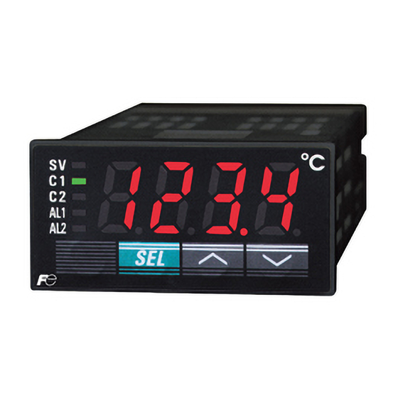
Model : PXR3
Thank you for your purchasing "Fuji Digital Temperature Controller." Please check that the product is
exactly the one you ordered and use it according to the following instructions. (Please refer to a separate
operation manual for details.) Dealers are cordially requested to ensure the delivery of this Instruction
Manual to hands of the end-users.
NOTICE
The contents of this document may be changed in the future without prior notice.
We paid the utmost care for the accuracy of the contents. However, we are not liable for direct and indirect
damages resulting from incorrect descriptions, omission of information, and use of information in this
document.
CONTENTS .......................................................
Check of specifications and accessories ...........
The related documents ......................................
Safety Precautions ............................................
.............................................................
1. Installation/mounting ...................................
2. Wiring ..........................................................
3. Usage (Read before using) .........................
4. Display and operation ..................................
1st block parameter .....................................
2nd block parameter ....................................
3rd block parameter ....................................
6. Functions .....................................................
6-1
ON/OFF control ..................................
6-2
Auto-tuning (AT) .................................
Instruction Manual
INP-TN2PXR3-E
CONTENTS
1
2
2
3
9
10
11
13
14
16
16
17
18
19
19
20
Global Sales Section
Instrumentation & Sensors Planning Dept.
1, Fuji-machi, Hino-city, Tokyo 191-8502, Japan
http://www.fujielectric.com
Phone: +81-42-514-8930 Fax: +81-42-583-8275
http://www.fujielectric.com/products/instruments/
6-3
Self-tuning .............................................
6-4
Alarm function (option) ..........................
6-5
Ramp/soak function (option) .................
6-6
Communication function (option) ..........
6-7
Alarm function (option) .......................... 27
6-8
Other functions ...................................... 28
6-9
Retransmission function (option) ........... 29
8. Error indications .............................................
[Table 1] Input type code ................................
[Table 2] Control output action code ...............
[Table 3] Input range (Standard range) ..........
[Table 4] Alarm action type code ....................
PXR Model Code Configuration .....................
Specification ...................................................
- 1 -
21
23
25
26
30
32
30
34
35
36
38
39
Advertisement
Table of Contents

Related Manuals for Fuji Electric PXR3


Summary of Contents for Fuji Electric PXR3
-
Page 1: Table Of Contents
Micro-controller X Phone: +81-42-514-8930 Fax: +81-42-583-8275 http://www.fujielectric.com/products/instruments/ Model : PXR3 INP-TN2PXR3-E Thank you for your purchasing “Fuji Digital Temperature Controller.” Please check that the product is exactly the one you ordered and use it according to the following instructions. (Please refer to a separate operation manual for details.) Dealers are cordially requested to ensure the delivery of this Instruction... -
Page 2: Check Of Specifications And Accessories
1 pc. (4-20mA DC input type only) The related documents For details, refer to the following documents. Contents Name Specifications Data sheet EDS11-182 MICRO-CONTROLLER X Operation (Model:PXR3) OPERATION TN5A2074-E method MANUAL COMMUNICATION FUNCTIONS (MODBUS) INP-TN512642-E Communication INSTRUCTION MANUAL COMMUNICATION FUNCTIONS... -
Page 3: Safety Precautions
Safety Precautions Before using this product, the user is requested to read the following precautions carefully to ensure the safety. Safety precautions must be taken by every user to prevent accidents. The safety requirements are classified into “warning” and “caution” according to the following interpretations : Suggesting that the user’s mishandling can result in Warning... - Page 4 Warning 1.1 Installation and wiring • This controller designed to be installed at the following conditions. -10 to + 50 [°C] Operating temperature Operating humidity 90%RH or less (Non condensation) Installation category Conforming to IEC1010-1 Pollution degree Location Indoor • The controller must be installed such that with the exception of the connection to the mains, creepage and clearance distances shown in the table below are maintained between the temperature probe and any other assemblies which use or generate a voltage shown in the table below.
- Page 5 • If there is a danger of a serious accident resulting from a failure or a defect in this unit, provide the unit with an appropriate external protective circuit to prevent an accident. • The unit is supplied without a power switch and fuses. Make wiring so that the fuse is placed between the main power supply switch and this controller.
- Page 6 Warning 2.1 Cautions on installation Avoid the following places for installation. • a place where the ambient temperature may reach beyond the range of from 0 to 50°C while in operation. • a place where the ambient humidity may reach beyond the range of from 45 to 85% RH while in operation.
- Page 7 Standard : Vertical mounting, flush on the panel. (The controller is horizontal.) When mounting the controller on tilted surface, the maximum tilt angle is 30° (degree) from vertical. (Caution) • Don’t block the openings around the controller, or radiation effect will be reduced.
- Page 8 [Proportional interval] relay output: 30 seconds or more, SSR/SSC: one second or more • If inductive load such as magnetic switches connected as a relay output load, it is recommended to use Z-Trap manufactured by Fuji Electric to protect a contact from switching serge and keep a longer life.
-
Page 9: Index
Index <Description> <Reference items> • Confirming that the delivered Confirming type specification controller is equal to the ordered one. • Outline dimensions Installation/mounting • Panel cutout dimensions • Mounting method on the panel Wiring • Terminal connection diagram Power on *Note •... -
Page 10: Installation/Mounting
1 Installation/mounting Outline and Panel Cutout Dimensions (Standard type/ Waterproof type) Outline dimensions (unit:mm) Waltertight packing Mounting bracket Panel thickness (1 t 8) Panel cutout dimensions (unit:mm) For separate mounting For mounting close together (n controllers) +0.5 +0.5 a=(48 × n – 3) 45.0 Number of units... -
Page 11: Wiring
2 Wiring Terminal Connection Diagram (100 to 240 VAC) or (24 VDC / 24 VAC) Digital input 1 DI 1 Control output 2 Communication Digital input 2 Relay SSR/SSC drive 4-20mA DC – RS-485 DI 2 – Alarm output 2 Re-transmission ALM2 4 to 20mA dc –... - Page 12 Designation of Wiring Material • Wire Gauge: AWG28 (0.1mm ) to AWG16 (1.25mm ) Strip-off length: 5 to 6 mm AWG28 to AWG16 5 to 6 mm • Rod terminal Dimension of exposed conductor section: 2 × 1.5 mm or smaller Length of exposed conductor section: 5 to 6 mm 5 to 6 mm 2MAX...
-
Page 13: Usage (Read Before Using)
3 Usage (Read before using) Name of Functional Parts and Functions Model : PXR3 Setting keys Name Function Select key The key shifting to the 1st, the 2nd or the 3rd block parameter, switching the display between parameter and the data at the 1st, the 2nd and the 3rd block. -
Page 14: Display And Operation
4 Display and operation Standby mode · To perform standby operation, set "STby" as ON in the 1st block parameter. Showing the process value (PV) Showing the set value (SV) SV indication lamp flickers SV indication lamp is lit Press the once once The set value (SV) flickers... - Page 15 Switching by Parameter setting mode Parameter settings Parameter selection Press the for 2 sec. Shift to operating condition Operation mode (SV display) Press the once. Parameter search. Parameter set value change. Increases parameter set value Decreases parameter Press the Press the set value Registers parameter set value, and returns to the parameter...
-
Page 16: Setting Methods Of Temperature And Parameters
Setting methods of temperature and parameters Operation/Standby mode SV indication lamp is lit when the set value is shown. · Some parameters may not be displayed on the screen, depending Control output status upon the types. Alarm status Press for about 1 sec. -
Page 17: 2Nd Block Parameter
Operation/Standby mode SV indication lamp is lit when the set value is shown. · Some parameters may not be displayed on the screen, depending Control output status upon the types. Alarm status Press for about 3 sec. Press for about 2 sec. -
Page 18: 3Rd Block Parameter
Operation/Standby mode SV indication lamp is lit when the set value is shown. · Some parameters may not be displayed on the screen, depending Control output status upon the types. Alarm status Press for about 5 sec. Press for about 2 sec. -
Page 19: Functions
6 Functions 6-1 ON/OFF control • t ON/OFF control mode,output signal is as shown below. Set parameter "P" = 0 for selecting the ON/OFF control mode. Set the hysteresis to avoid chattering. (Default setting: HYS = 1) • Parameter setting and operation example Example 1 : Reverse operation Parameter Setting value... -
Page 20: Auto-Tuning (At)
6-2 Auto-tuning (AT) Auto-tuning is the automatic calculation and entering of the control parameters (P,I and D) into memory. Prior to the auto-tuning, complete the setting of input range (P-SL,P-SU, P-dP), a set value (SV), alarm setting (AL1, AL2), and cycle time (TC). How to start the auto-tuning Set the parameter AT as either “1”... -
Page 21: Self-Tuning
6-3 Self-tuning 1) At power on, changing a set value or the external disturbance, tuning is made automatically so that the PID parameters are re-optimized. It is useful where modification of PID parameters is required repeatably due to frequent change in process condition. - Page 22 4) Self-tuning is executed by any of the following conditions. (1) During temperature rise at power ON. (2) During temperature rise at SV changing if necessary. (3) When control is out of stable condition and is judged as being out of stable condition continuously. 5) Self-tuning is not executed under the following conditions: (1) During standby mode (2) During ON/OFF control...
-
Page 23: Alarm Function (Option)
6-4 Alarm function (option) 1) Kinds of alarm • Absolute value alarm, deviation alarm, combination alarm, and zone alarm are available. (For details, see Table 4, Alarm action type codes on page 4.) ON delay Alarm function Without ON delay function With ON delay function ON delay setting time Energizing/de-energizing... - Page 24 Combination of alarm functions Please see the table as shown below. O: Possible combination X: Impossible combination Without HOLD/Timer With HOLD With Timer Alarm latch De-energizing Note 1 ON delay Alarm in error status If HOLD has not been canceled, the HOLD state is canceled as soon as Note 1 the measured value goes out of alarm band.
-
Page 25: Ramp/Soak Function (Option)
6-5 Ramp/soak function (option) 1. Function Changes the set value (SV) as the time elapses according to a predetermined program pattern, as shown below. Either 4 ramp/soak x 2 patterns or 8 ramp/soak x 1 pattern can be programmed. The first ramp starts from the process value (PV) just before the programming is executed. -
Page 26: Communication Function (Option)
6-6 Communication function (option) 1) Function Data can be written/read through the RS-485 communication. 2) Before using this function, please set related parameters as shown below. 3rd block parameter Set the station No. at “STno” Set the parity at “COM”. Please do not change “PYP”... -
Page 27: Alarm Function (Option)
6-7 Alarm function (option) 1) Function With Digital input, the follwing functions are available. (1) SV switching (2) Control mode; RUN/STANDBY (3) Ramp/soak RUN/RESET selection (4) Auto-tuning start/stop (5) Alarm latch cancel (6) Timer start/reset 2) To use DI function; •... -
Page 28: Other Functions
6-8 Other functions The parameters “bAL” and “Ar” are masked at default setting. If necessary to appear these parameters, please refer to the following procedure. 1) Function • “bAL” and “Ar” are functions to suppress overshoot. (Usually it is not necessary to change the setting.) 2) If they aren’t optimum value, sometime you don’t get the good control. -
Page 29: Retransmission Function (Option)
6-9 Retransmission function (option) 1) Function • It is the function that outputs one of signals as shown below with current such as 4 to 20mA dc. Output type: PV, Setpoint, Output or Error. 2) TBefore using this function, please set related parameters as shown below 3rd block parameter Setting output type for Setting lower... -
Page 30: Setting Of Input Type And Control Algorithm
Setting of input type and control algorithm Setting of the input type * Skip this procedure if the input type is specified when you order. (1) Please check if the input type set at “P-n2” is same as what you use. Choose the sensor type you use from Table 1 shown below, and set the code at “P-n2”. - Page 31 Setting of the algorithm * Read if the control doesn't work as you expect. (1) Select the type of control output action. Control Setting procedure Description output action Heating Reverse Set parameter “P-n1” = 0 or 1. As PV increases, MV decreases. (Refer to Table 2) As PV decreases, MV increases.
-
Page 32: Error Indications
-150 ˚C. Incorrect range setting (P-SL/P-SU). OFF or 4mA or less (SV indication flickers) Fault in the controll. Undefined (Stop using this controller immediately.) Contact with Fuji Electric Co.,Ltd. or the nearest repesentatives. – 32 –... - Page 33 [Table 1] Input type code Parameter : Group Input type Code Group Input type Code 1 to 5V DC, 4 to 20mA DC · Pt100 (IEC) In case of 4 to 20mA DC input, mount a 250 Thermocouple resistor enclosed in the package box. ·...
-
Page 34: [Table 2] Control Output Action Code
[Table 2] Control output action code Parameter : Control output action Output at Burn-out* Code Output Output 1 Output 2 Output 1 Output 2 Lower limit Reverse action Upper limit Single Lower limit (Control output 1) Direct action Upper limit Lower limit Lower limit Upper limit... -
Page 35: [Table 3] Input Range (Standard Range)
[Table 3] Input range (Standard range) Parameter : Range Range Range Range Input signal type Input signal type (ºF) (ºF) (ºC) (ºC) RTD (IEC) Pt100Ω 0 to 150 32 to 302 Thermo- 0 to 1600 32 to 2912 Pt100Ω 0 to 300 32 to 572 couple 0 to 1800... -
Page 36: [Table 4] Alarm Action Type Code
[Table 4] Alarm action type code Parameter : · Standard alarm code · Alarm code with dual set value ALM1 ALM2 Alarm type Action diagram ALM1 ALM2 Alarm type Action diagram High High/Low /Low No alarm absolute alarm limit A1-L A1-H A2-L A2-H... - Page 37 What is alarm with hold? Point The alarm is not turned ON immediately even when the mesaured value is in the alarm band. It turns ON when it goes out the alarmband and enters again. PV (process value) Power ON Power OFF Power ON Period where lower...
-
Page 38: Pxr Model Code Configuration
PXR Model Code Configuration 4 5 6 7 8 9 10 11 12 13 Digit Specification <Size of front H × W> 24 × 48mm <Input signal> Thermocouple ºC Thermocouple ºF RTD Pt100 3-wire type ºC RTD Pt100 3-wire type ºF 1 to 5VDC 4 to 20mA DC... -
Page 39: Specification
*1 : The following table shows the difference of outputs among other micro-controller X series models. Allowable load SSR/SSC driving output resistance for 4 to Voltage Maximum current 20mA DC output PXR3 15V DC 20mA 100 to 500 PXR4 24V DC 20mA...
Need help?
Do you have a question about the PXR3 and is the answer not in the manual?
Questions and answers