Fuji Electric PXR3 Operation Manual
Micro-controller x
Hide thumbs
Also See for PXR3:
- Operation manual (74 pages) ,
- Instruction manual (39 pages) ,
- Instruction manual (4 pages)
Table of Contents
Advertisement
Quick Links
Advertisement
Table of Contents

Related Manuals for Fuji Electric PXR3


Summary of Contents for Fuji Electric PXR3
- Page 1 Micro-controller X Model: PXR3 Operation Manual ECNO:409b...
-
Page 2: Table Of Contents
Table of Contents 1 Part Names and Functions ....................5 2 Operations ..........................6 2-1 Parameter list ......................6 2-2 Basic operations ....................... 11 2-3 Parameter functions and method of settings ............12 ① First block parameters ....................13 Standby setting ......................13 Ramp-soak control ..................... - Page 3 ③ Third block parameters ....................49 Specifying control system and action, and output direction at input burn-out .... 49 SV (Setting value) lower limiter .................. 50 SV (Setting value) upper limiter ................. 50 The time of ON-delay alarm or timer function ............51 Hysteresis alarm 1 and 2 ...................
- Page 4 4 5 6 7 8 9 10 11 12 13 Model Specifications digit Specification Note <Size of front H x W> 24 × 48 mm <Input signal> °C Thermocouple °F Thermocouple °C RTD Pt100Ω 3-wire type °F RTD Pt100Ω 3-wire type 1 to 5V DC 4 to 20mA DC <Control output 1>...
-
Page 5: Part Names And Functions
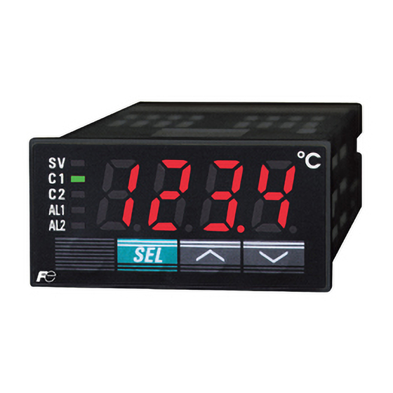
Lamp for alarm output 1 ③ Lamp for alarm output 2 ④ ⑥ key ⑦ key Type: PXR3 q Lamp for control output 1 Lights up while control output 1 stays ON. Used to switch the PV display to/from the SV display... -
Page 6: Operations
Operations This chapter explains how to set the SV (Setting value) and the parameters for the PXR. 2-1 Parameter list Parameters for the PXR are classified under three blocks according to the frequency of use. The parameters of the second and third blocks are used at initialization or when they are of absolute necessity. - Page 7 Note: The parameters for which * is marked with the page number in Parameters of the second block Reference page are related to Remedies of “4” on page 70. Parameter Setting range and factory User’s Parameter Reference Parameter name Description default setting (*) display symbol set value...
- Page 8 Parameter Setting range and factory User’s Parameter Reference Parameter name Description display symbol default setting (*) set value mask DSP page dSP6-32 1st soak Sets the 1st soak segment time. 0 to 99h59m (*: 0.00) TM1S segment time dSP6-64 Sets the 2nd target SV of ramp-soak Within the SV limit.
- Page 9 Note: The parameters for which * is marked with the page number in Parameters of the third block Reference page are related to Remedies of “4” on page 70. Parameter Setting range and factory User’s Parameter Reference Parameter name Description display symbol default setting (*) set value...
- Page 10 Parameter Setting range and factory User’s Parameter Reference Parameter name Description display symbol default setting (*) set value mask DSP page dSP1 dSP9 Sets whether or not to display each 0 to 255 (*: specified by customer Parameter mask – parameter.
-
Page 11: 2-2 Basic Operations
The PV (process value) is displayed just after power-on. Exp.) In case when the PV (process value) is 149.9. How to switch parameters: The figure below shows the basic operations for the PXR3. Basic operations for the PXR3 Display state just after power-on Parameter setting... -
Page 12: 2-3 Parameter Functions And Method Of Settings
2-3 Parameter functions and method of settings Method of setting the SV (Setting value) [Description] Related parameters: (page 50) • The SV is a target value for control. (page 50) • Any SV that is outside of the range set in the parameters (lower limit) and (upper limit) of the third block cannot be set. -
Page 13: ① First Block Parameters
q First block parameters Standby setting (Settings: oFF/on) [Description] • This parameter switches the control between RUN and • The other operations are the same as those of the ramp- Standby. soak standby. • During standby, the control output and the alarm output •... -
Page 14: Ramp-Soak Control
Ramp-soak control (Settings: oFF/rUn/hLd) (Option) [Description] • This function automatically changes the SV (Setting Up to SV-8 value) according to the program pattern set in advance as shown in the right line graph. Up to eight pairs of ramp- SV-3 soak operation can be programmed. -
Page 15: Canceling The Alarm Latch
Canceling the alarm latch (Setting range: 0/1) (Option) [Description] • This parameter cancels the alarm latch when it is latching. Related parameters: (page 54) [Setting example] Opening up the alarm latch Display Operating procedure Press and hold the key for one second. PV indication will be displayed. -
Page 16: Auto-Tuning Function
Auto-tuning function (Settings: 0/1/2) [Description] [Note] • There are two codes for AT: If the controller is powered off during auto-tuning, this Setting code [1]: SV standard type makes the auto-tuning ineffective with each parameter Performs the auto-tuning based on the SV. of , , and unchanged. -
Page 17: Displaying On-Delay Alarm Or The Remaining Time Of Timers
Displaying ON-delay alarm or the remaining time of timers (unit: seconds) (Option) [Description] • These parameters display the remaining time of Timers 1 , display parameter • and 2. • The remaining time of the ON/OFF-delay timer is counted down. When the counter shows , the alarm relay is closed. -
Page 18: Setting Alarm 1 And 2
(Setting range: Setting alarm 1 and 2 Absolute value alarm: 0 to 100%FS Upper limit of alarm 1 and 2 Deviation value alarm: -100 to 100%FS ) Lower limit of alarm 1 (Option) and 2 [Description] [Note] • These parameters are used to for settings of alarm 1 and 2. -
Page 19: Key Lock
Key lock (Setting range: 0−5) [Description] • There are six levels of the key lock: • This parameter makes the set values of parameters : Unlocked (reset) unchangeable. However, the parameter name and the set : All settings are unchangeable from the controller, but values can be displayed. -
Page 20: ② Second Block Parameters
w Second block parameters Proportional band (Setting range: 0.0 to 999.9% of the measured range) [Description] • To select the ON/OFF control (two-position control), set • Set the hysteresis of the ON/OFF control (two-position to 0.0. It is not necessary to set and . -
Page 21: Integral Time
Integral time (Setting range: 0 to 3200 seconds) [Description] • When is set to 0, the integral operation does not start. • can be set automatically by the auto-tuning operation. • When is set to 0.0, this makes the setting of ineffec- •... -
Page 22: Derivative Time
Derivative time (Setting range: 0.0 to 999.9 seconds) [Description] • When is set to 0, the differential operation does not start. • can be set automatically by the auto-tuning operation. • When is set to 0.0, this makes the setting of ineffective. -
Page 23: Hysteresis Range For On/Off Control
Hysteresis range for ON/OFF control (Setting range: 0 to 50%FS) [Description] [Ex] Input Thermocouple K : At measured range of 0 • To select the ON/OFF control (two-position control), set to 400 ºC, the setting to 0.0. It is not necessary to set range is 0 to 200 ºC. -
Page 24: Cooling-Side Proportional Band Coefficient
Cooling-side proportional band coefficient (Option: Available for DUAL output only) (Setting range: 0.0 to 100.0) [Description] • This parameter is used for setting the cooling-side pro- • When is set to 0.0 and is set to 0.0 in the dual portional band. -
Page 25: Cooling-Side Proportional Band Shift (Dead Band/Overlap Band)
Cooling-side proportional band shift (Dead band/Overlap band) (Option: Available for DUAL output only) (Setting range: -50.0 to +50.0) [Description] • When is a positive value, it is called the "Dead band", • This parameter is used for shifting the cooling-side pro- and when it is a negative value, the "Overlap band". -
Page 26: Output Offset Value
Output offset value (Setting range: -100.0 to 100.0 %) Anti-reset windup (Setting range: 0 to 100%FS) [Description] • The anti-reset windup ( ) is automatically set to an optimum value by the auto-tuning operation. In this range, the integral operation is not performed. By setting , the amount of overshoot can be adjusted. -
Page 27: Control Algorithm
Control algorithm (Settings: PID/FUZY/SELF) [Description] • For the ON/OFF control (Two-position control), select • This parameter is used for selecting PID control, FUZZY- the PID control and then set to 0.0. For detailed infor- PID control, or PID control with self-tuning. mation, refer to (page 20). - Page 28 [Self-tuning] 1 Function: With the self-tuning function, PID parameters are automatically re-optimised depending on the actual condition of device to be controlled and the setting temperature (SV). 2 How to execute: Follow the procedure shown below to set and execute the self-tuning. The self-tuning starts to run at the appropriate conditions.
- Page 29 3 Conditions under which the self-tuning runs: q At power-on: The self-tuning runs when all of the following conditions are met. • The SV that appears at power-on is not the same one when the , and were set previously. (i.e. , and set by the self-tuning, auto-tuning, manual setting, and writing by communications tools at previous time)
- Page 30 7 Reference [About the self-tuning method] The PID constant is calculated in one of the following two methods. The method is selected automatically depending on the characteristics of the device to be controlled. • Step response method • Limit cycle method The following figures show the operations at power-on and changing the SV, and under unstable control.
-
Page 31: Pv (Measured Value) Stable Range
PV (Measured value) stable range (Setting range: 0 to 100%FS) [Description] • Self-tuning logic recognizes that control is stable if PV is • It is not necessary to set this parameter under normal con- staying within the SV ± ditions. [Setting example] Changing the PV stable range from 2 to 3 Display Operating procedure... -
Page 32: Hys (Hysteresis) Mode At On/Off Control
HYS (Hysteresis) mode at ON/OFF control (Settings: oFF/on) [Description] • This parameter is used for selecting the hysteresis opera- onoF : OFF onoF : ON tion mode at ON/OFF control. Starts the ON/OFF control at the values of and SV- Starts the ON/OFF control at the values of SV and SV+HYS, or SV and SV-HYS. -
Page 33: Cycle Time Of Control Output 1
Cycle time of control output 1 (Setting range: 1 to 150 seconds) [Description] • This parameter is applicable for to the contact output and For contact output: SSR-driving output. The higher the frequency of output is, the more precise • While input is within the proportional band, output the control becomes. -
Page 34: Cycle Time Of Control Output 2 (Cooling-Side)
Cycle time of control output 2 (Cooling-side) (Setting range: 1 to 150 seconds) (Option: Available for DUAL output only) [Description] For contact output: • By this parameter is set, the cycle time of control output 2. The higher the frequency of output is, the more precise •... -
Page 35: Input Signal Code
Input signal code (Setting range: 0 to 16) [Description] • Input signals and codes • This parameter is used for selecting input signals. Input q Input signals code table signal varies depending on the sensors (2 types below). Set a code that corresponds to the sensor you use. Code Type Input signal... -
Page 36: Setting Lower Limit Of The Measuring Range
Setting lower limit of the measuring range (Setting range: -1999 to 9999) Setting upper limit of the measuring range (Setting range: -1999 to 9999) Selection ˚C / ˚F (Setting: ˚C or ˚F ) [Description] w Input range table (Standard range) •... - Page 37 [Setting example] Changing the measuring range from 0°C to 150°C to -100°C to 200°C (Pt100) Display Operating procedure Press and hold the key for three seconds. PV indication will be displayed. Press the key to display Press the key once. The current setting ( ) will be displayed.
-
Page 38: Decimal Point Position
Decimal point position (Settings: 0 / 1 / 2) [Description] • This parameter is used for selecting the number of decimal Related parameters: (page 36) point positions for the process value (PV) . (page 36) "0" (No digit after decimal point) "1"... -
Page 39: Pv Offset
PV offset (Setting range: -10 to 10%FS) [Description] • With this function, predetermined value is added to the in- • The PXR3 operates at the displayed PV (the value to put reading. This parameter is used for adjusting PXR3’s which the PV offset value is added). -
Page 40: Sv Offset
P control. • When the retransmission output type is set to the SV, the • The PXR3 operates based on the SV to which the SV off- displayed SV, to which the SV offset value is not added, set value is added. -
Page 41: Time Constant Of Input Filter
Time constant of input filter (Setting range: 0.0 to 900.0 seconds) [Description] • This parameter is used for reducing the fluctuation of in- Input put signal (filter function). Control output filter For example, when the input filter constant is set to 5 seconds, the PV changes as shown in right figure while input changes from 0 to 100% suddenly. -
Page 42: Alarm Types
Alarm types (Setting range: 0 to 34) (Option) [Description] • These parameters are used for selecting the operation types [Note] of Alarms 1 and 2. • Since the alarm set value may change after changing the • Alarm1 is activated in the same way as Alarm2 except for codes alarm operation types, be sure to set the alarm set value 12 to 15. - Page 43 [Alarm type list] The table below shows the meaning of symbols in the following operation figures. Alarm 1 Alarm 2 Alarm type Screen name Display symbol Screen name Display symbol Set value of Alarm 1 Set value of Alarm 2 0~15 Lower-limit of set value of Alarm 1 A1-L...
- Page 44 • Alarm codes with dual set values Alarm type Operation figure ALM1 ALM2 ALM1 ALM2 Alarm type Operation figure Range upper Upper and Upper Range and lower limits lower limits A1-L A1-H A1-L A1-H alarm absolute value absolute value A2-L A2-H A2-L A2-H...
-
Page 45: Selecting Ramp-Soak Patterns
Selecting ramp-soak patterns (Settings: 1 / 2 / 3) (Option) [Description] [Note] • This parameter becomes effective when the ramp-soak operation is changed from • This parameter is not effective if it is changed during RUN • Setting range or HOLD. : Performs 1st to 4th segments. -
Page 46: Ramp-Soak Status Display
Ramp-soak status display (Display only) 1st to 8th target SV (Setting range: ) (Option) 1st to 8th ramp segment time (Setting range: 0 to 99h 59min) (Option) 1st to 8th soak segment time (Setting range: 0 to 99h 59min) (Option) Ramp-soak modes (Setting range: 0 to 15) (Option) [Description] •... - Page 47 Parameter Factory Name Remark Description display symbol default settings STAT Current program Displays the Ramp-soak current status. status This parameter is only for display, and cannot set anything. : OFF : Under the 1st to 8th ramp operation : Under the 1st to 8th soak operation : Ends the program symbol appears...
- Page 48 • The segment in which both the ramp time and soak time are set to "0" is skipped. [Ex] SV-1: 50 SV-2:200 SV-3:100 TM1r:0.10 TM2r:0.00 TM3r:1.00 TM1r TM1S TM3r TM3S TM1S:0.05 TM2S:0.00 TM3S:0.75 • The SV limit function is valid even while the ramp-soak Pattern of the program operation is running.
-
Page 49: ③ Third Block Parameters
e Third block parameters Specifying control system and action, and output direction at input burn-out (Setting range: 0 to 19) [Description] • This parameter specifies action (Single/Dual and Heating/ • Control operation code table Cooling), and output direction at input burn-out. Control action Burn-out output* Code... -
Page 50: Sv (Setting Value) Lower Limiter
SV are affected by the SV limiter. So, after setting the ramp-soak operation to OFF, or returning the switched SV to the original SV, the PXR3 operates with the SV0 affected by the SV limiter. -
Page 51: The Time Of On-Delay Alarm Or Timer Function
The time of ON-delay alarm or timer function (Setting range: 0 to 9999 seconds) (Option) [Description] • The timer display function shows the remaining time of ON-delay alarm timers 1 and 2. • With this function, the alarm relay is closed after the pre- determined delay time. - Page 52 [Setting example] Setting the delay time for ON-delay alarm to 30 seconds Display Operating procedure PV indication Press and hold the key for five seconds. will be displayed. Press the key to display Press the key once. The current setting ( ) will be displayed. Press the keys to flicker and to display Press the...
-
Page 53: Hysteresis Alarm 1 And 2
Hysteresis of alarm 1 and 2 (Setting range: 0 to 50% FS) (Option) [Description] • Hysteresis can be set for each alarm. • The alarm is detected in the two-position operation (ON/ OFF). The hysteresis means the difference between the input at ON and the input at OFF. -
Page 54: Options Of Alarm 1 And 2
Options of alarm 1 and 2 (Setting range: 000 to 111) (Option) [Description] • The de-energized output alarm function is used for ener- • These parameters are used to switch ON/OFF the alarm gizing or de-energizing the alarm relay to be closed. While latch, the error satus alarm, and the de-energized output this function is set to ON, when the alarm judgment shows alarm functions for each of Alarm 1 and 2. - Page 55 [Setting example] Setting the error status alarm function for Alarm 2 to ON Display Operating procedure PV indication Press and hold the key for five seconds. will be displayed. Press the key to display Press the key once. The current setting ( ) will be displayed.
-
Page 56: Upper And Lower Limits For Control Output 1
Upper and lower limits for control output 1 (Setting range: -3.0 to 103.0%) Upper and lower limits for control output 2 (Setting range: -3.0 to 103.0%) (Option: only for DUAL type) [Description] • These parameters set the limit value of output. Upper limit Lower limit 30 (seconds) -
Page 57: Output Limit Types
Output limit types (Setting range: 0 to 15) [Description] • This parameter sets whether to maintain the value within Output 1 Output 2 the limit or to break the limit when the output value in- PCUT Upper limit Lower limit Upper limit Lower limit creases up to the limit set value. -
Page 58: Output Value Display
Output value display (Display only: -3.0 to 103.0%) [Description] • These parameters display the output values of outputs 1 and 2 in the unit of %. (Since the values are calculated with the software, they may have some error comparing to the actual output.) [Setting example] Confirming the output value (the calculated value) of control output 1 Display... -
Page 59: Rcj (Cold Junction Compensation)
RCJ (Cold junction compensation) (Setting range: ON/OFF) [Description] • Set this parameter to OFF under the conditions that the • This parameter sets whether or not to perform the RCJ RCJ is not needed, such as when the RCJ is performed (Cold junction compensation) for the thermocouple in- outside of the PXR or when the temperature deviations put. -
Page 60: Adjusting The Pv (Measured Value) Display (0%)
Adjusting the PV (Measured value) display (0%) (Setting range: -50 to 50% FS) Adjusting the PV (Measured value) display (100%) (Setting range: -50 to 50% FS) [Description] • The user-definable functions are independent of the adjust- Return the parameter of to ON. -
Page 61: Di Operation
DI operation (Setting range: 0 to 12) (Option) [Description] • The ramp-soak operation can be also switched between • Select each DI function with (DI set- RUN/RESET manually. ting parameter) and set the DI to ON to activate the func- •... - Page 62 Starting the auto-tuning (DI functions 3, 4) • These functions can switch the start/stop of the auto- tuning. DI function DI ON edge DI OFF edge AT (Standard) AT start AT cancel AT (Low PV) Cancel the alarm latch (DI functions 5 to 7) •...
- Page 63 [Setting example] Changing the SV (Front SV) to SV1 Display Operating procedure Press and hold the key for five seconds. PV indication will be displayed. Press the key to display Press the key once. The current setting ( ) will be displayed. Press the keys to flicker and to display .
-
Page 64: Station No. For Communication
Station No. for communication (Setting range: 0 to 255) (Option) [Description] • Do not set the same number as other Micro-controllers. [Setting example] Setting the station No. to "123" Display Operating procedure Press and hold the key for five seconds. PV indication will be displayed. -
Page 65: Parity For Communication
However, it does not switch to the even parity at this point. (Repeat the procedure from 3 to 5 to check the set value.) Power off the PXR3, and then on. The even parity is set now. SV indication If you want to display the operation status, press and hold the key for two seconds. -
Page 66: Input Type For Pyp
(Thermocouple B) will be registered for the input range. After that, PYP will recognize the input range of the PXR3 as thermocouple B ( 0 to 1800˚C). (Repeat the procedure from 3 to 5 to check the set value.) -
Page 67: Retransmisson Output Type Setting
Retransmission output type setting (Setting range: 0 to 3) (Option) [Description] • This parameter is used to set the retransmission output type. The means of the set values are as shown below. Set value Output type Related parameters: (page 68) (page 68) [Setting example] Changing the retransmission output type from the process value (PV) to the set value (SV) -
Page 68: Retransmisson Base Scale
Retransmission base scale (Setting range: -100.0 to 100.0%) (Option) Retransmission span scale (Setting range: -100.0 to 100.0%) (Option) [Description] • The retransmission base scale and span scale can be set • When the value of retransmission output (example: SV) as shown below. Unit for the setting is %. becomes equal to the set value of Ao-L, the retransmis- sion output becomes 0% (output). -
Page 69: Parameter Display Mask
Parameter display mask (Setting range: 0 to 255) [Description] • "Parameter mask DSP" in "2-1 Parameter list" (page 6) • This parameter skips the parameter display by items. shows which parameter is skipped by setting • This parameter is used not to display the items that are not used, or not to change the settings mistakenly. -
Page 70: Troubleshooting
The sensor or other input devices that are Replace the sensor or other input devices with new ones. connected to the PXR3 have problems. i The set value of the parameter of Set the parameters again so that the value of... - Page 71 Reference Symptoms Possible causes Remedies pages 8. Response is too slow. (The mea- Decrease the set value of the parameter Page 39 Input filter constant is too large. sured value changes slowly.) 9. Output changes be- q Some input terminals are short-circuited. Remove the short-circuited terminals.
-
Page 72: Index
Index Adjusting the PV display (0%) ............60 ON/OFF control (two-position control) ......... 20 Adjusting the PV display (100%) ........... 60 Operations ..................6 Alarm codes ..................43 Options of alarm 1 and 2 ..............54 Alarm of input error status ............. 54 Output direction at input burn-out .......... - Page 73 Memo...
- Page 74 Safety Precaution Before using the PXR3, read the “Instruction Manual” or consult with your local distributor or Fuji Electric for safety purpose. The uses and places for some of equipment described in this manual are limited. Some devices need regular inspec- tions.
Need help?
Do you have a question about the PXR3 and is the answer not in the manual?
Questions and answers