Advertisement
Quick Links
Instruction Manual
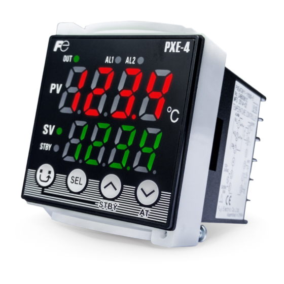
Micro Control X
Model : PXE4
INP-TN2PXE4-E
Thank you for your purchasing "Fuji Digital Temperature
Controller." Please check that the product is exactly the one
you ordered and use it according to the following instructions.
(Please refer to a separate operation manual for details.)
Dealers are cordially requested to ensure the delivery of this
Instruction Manual to hands of the end-users.
Safety Precautions
Before using this product, the user is requested to read the fol-
Before using this product, the user is requested to read the fol-
lowing precautions carefully to ensure the safety. Safety precau-
lowing precautions carefully to ensure the safety. Safety precau-
tions must be taken by every user to prevent accidents.
tions must be taken by every user to prevent accidents.
Failure to comply with the instructions contained in this manual
Failure to comply with the instructions contained in this manual
may reduce the safety of the instrument.
may reduce the safety of the instrument.
Suggesting that the user's mishandling can result in
Warning
personal death or serious injury.
Suggesting that the user's mishandling can result in
Caution
personal injury or damage to the property.
4 5 6 7 8
9
10 11 12 13
PXE
4 T
Y
2 -
Y 0 0 0
Digit
Specification
Note
4
<Front
dimensions>
48 X 48mm
4
5
<Input signal>
Thermocouple · Resistancabulb (°C)
T
6
<Control output>
Relay contact output
A
SSR driving output
C
−
7
Y
8
<Revision code>
2
9
<Optional specifications>
*1
Alarm (1 pc.)
1
Alarm (2 pc.)
2
Alarm (independent common)
J
10
<Power supply voltage, Instruction manual>
100 to 240V AC, Japanese/English/Chinese
Y
*1: When using the controller for dual control (heating/cooling), the alarm output 1 functions as the control output 2.
Input signal, measurement range, and set value at the time of deliver are as follows.
Input signal of the thermocouple and the resistance bulb can be switched by key
operation on the front panel.
2. Scope of Delivery
Temperature controller ....1 unit
Mounting bracket .........1 pcs
Instruction manual ...........1 copy
6. Operation Flow Diagram
Power is ON
[Operation Ch.]
[Channel 1]
key
100
Process value (PV)/
P
Setting value (SV)
26
5 . 0
SEL key
ST b y
i
Standby setting
OF F
2 4 0
SEL key
AT
d
Auto-tuning
o F F
6 0 . 0
SEL key
Hy S
A L 1
Alarm 1 set value
0
2 5
SEL key
CooL
A L 2
Alarm 2 set value
0
1 . 0
SEL key
db
L o C
Key lock
OF F
0 . 0
SEL key
*1
These parameters are not displayed
when shipping.
It can be displayed by other parameter
setting.
*2
Display ON/OFF is switched by other
parameter setting.
8. List of Setting Parameter
Operation parameter
Parameter
Parameter
Description of contents
display symbol
1
Process value and setting value
2
Standby settings
3
Auto-tuning
4
Alarm 1 set value Trigger point for the alarm 1. Used to configure the alarm 1 in combination
with the "Alarm type". Setting is available within the input range.
5
Alarm 2 set value Trigger point for the alarm 2. Used to configure the alarm 2 in combination
with the "Alarm type". Setting is available within the input range.
Restriction on parameter change
Parameter
Parameter
Description of contents
display symbol
7
Proportional band
Integral time
9
Derivative time
10
Hysteresis for
11
band coefficient
12
Dead band
Offset of the cooling proportional band against the set value
13
Output
Offset added to the MV output
convergence value
14
15
OUT 1 proportional
control cycle
OUT 2 proportional
control cycle
17
Define the control action.
action
control)
1.
Warning
1.1 Installation and wiring
Operating temperature
Operating humidity
90%RH or less (Non condensation)
Installation category
II
Pollution degree
2
creepage and clearance distances shown in the table below are maintained between the
temperature probe and any other assemblies which use or generate a voltage shown in the table
below.
Voltage used or generated by any assemblies
Up to 50Vrms or Vdc
0.2
Up to 100Vrms or Vdc
0.2
Up to 150Vrms or Vdc
0.5
Up to 300Vrms or Vdc
1.5
Above 300Vrms or Vdc
between all terminals of this controller and the ground, and supplementary insulation is required for
the alarm output.
Isolation class of this controller is as shown below. Be sure to check that the isolation class of the
controller satisfies your requirements before installation.
Basic insulation (1500V AC)
Functional insulation (500V AC)
Power source
Contact output 1(relay contact)
Alarm output 1 (relay contact) or
Alarm output 1 (relay contact) or
contact output 2 (relay contact)
contact output 2 (relay contact)
Alarm output 2 (relay contact)
Alarm output 2 (relay contact)
When the 9th code is "J" Alarm
When the 9th code is other than "J"
output 1 and 2: independent common
Alarm output 1 to 2: shared common
-
-
Make wiring so that the fuse is placed between the main power supply switch and this controller.
completed.
ON.
malfunction.
3. Outline and Panel Cutout Dimensions
14
Outline dimensions
-
E
2.6
1
48
OUT1
OUT2/AL1
AL2
PV
SV
Panel
STBY
STBY
AT
Water-proof
packing
t
Panel cut
When units installed side by side (n units)
45
+0.5
0
NEMA 4X/IP66 (front water-proof) is
not available, since packing can not
63MIN.
be used when unit installed side by
side.
Note) this dimensions is
including paint thickness
[Channel 2]
[Channel 3]
Ch 1.is displayed
Ch 2.is displayed
key
key
Ch 2
Ch 1
SEL key
SEL key
P v T
Proportional band
Input type setting
K1
SEL key
SEL key
P v o F
Integral time
PV offset
0
SEL key
SEL key
Derivative time
SEL key
b A L
Output
Hysteresis for
convergence value
0 . 0
On/OFF control
SEL key
SEL key
Cooling proportional
CT r L
Control method
band coefficient
onoF
SEL key
SEL key
Cycle time
T C
Dead band (%)
(control output1)
3 0
SEL key
SEL key
T C2
Cycle time
3 0
(control output2)
SEL key
r E v
Setting of Normal
r E v S
/Reverse action
SEL key
Default setting
Note
19
-
OFF
OFF
a
20
21
22
2.5% of range
i, e
23
2.5% of range
b, e
24
OFF
Default setting
Note
5.0%
a
240 seconds
a
a
2.5% of range
c
1.0
9. Error Indications
This controller has a display function to indicate several types of error code shown below.
0.0%
k
If any of the error codes is displayed, please eliminate the cause of error immediately.
After the cause is eliminated, turn off the power once, and then re-start the controller.
0.0%
a
onoF
a
30 seconds
revS
(SV indication flickers)
may result in a malfunction, electric shock, or a fire.
safety, use a protective circuit outside.
1.2 Maintenance precautions
shock, malfunction, and fault.
controller have a limited life span, or they will be deterio-rated with the lapse of time.
properly used.
2.
Caution
2.1 Cautions on installation
1.2
Avoid the following places for installation.
1.4
operation.
3.0
operation.
emitted.
(Vibration or shock may cause output relay malfunction.)
(if immersed with water, take the inspection by sales office to avoid an electr-ical leakage and firing)
Non-insulation
Measured value input
Internal circuit
2.2 Caution on installation on panel
Control output 1 (SSR drive)
panel. If there are some gaps, tighten two screws until the gaps are eliminated. (Do not tighten the
waterproofness between the instrument and the panel, use packings that are provided as
① As shown in Figure 1, fit a packing to the case of the unit and then insert it in the panel.
②
shown in Fig.3.
water resistance.
Figure 1
Figure 2
Unit
Front
Packing
Panel
Note) Panel coating procedure must be taken into account, for the panel cutout
dimension should still conform with the dimensions listed.
Mounting frame
(Installation of fan is recommended as a heat release measure)
60.9
an instrument of more than 70mm depth or a wall on the right side of the
controller.
Three-year warranty does not cover in case of side by side installation.
relay terminal)
4. Terminal Connection Diagram
panel thickness ( t)
1 t 8
Alarm output
①
②
+0.5
(48×n-3)
0
③
①
②
③
④
7. List of Alarm Type
Type
Alarm type
key
0
No alarm
Ch 3
Ch 3.is displayed
1
Upper limit
SEL key
A L M1
2
Absolute
Type of alarm 1
0
value
SEL key
Upper limit
alarm
3
(with hold)
A L M2
Type of alarm 2
0
4
(with hold)
SEL key
L b T M
Loop break
5
Upper limit
detection time
0
SEL key
L b A b
Loop break
detection band
0
SEL key
7
Deviation
dSPC
Switchover of
0PE
parameter display
alarm
Upper limit
SEL key
(with hold)
9
(with hold)
10
(with hold)
Zone
11
alarm
Break
12
Parameter
Parameter
Description of contents
display symbol
Input type
Input type
PV offset
Parameter
Parameter
Description of contents
display symbol
Alarm type 1
Alarm type 2
Open loop
Time until the loop is assumed to be open.
detection time
Open loop
Temperature range by which the loop is assumed to be open.
detection band
A set of parameters to be displayed on the controller. Refer to the
of parameter
operation manual for the detail.
display
f
Returns to the operator level every time the power is turned off.
h
Refer to "10. Measuring input signal".
Possible cause
① Thermocouple burnt out.
② RTD (A) line burnt out.
③
①
②
③
① PV value < –199.9
2.3 Precautions in wiring connection
For the RTD type, use a wiring material with a small lead wire resistance and no resistance
differentials among three wires.
other.
transformer and the use of a noise filter are recommended.
Make sure that the noise filter is installed to a place such as a panel that is properly grounded. The
wiring between the noise filter output terminal and the instrument power supply terminal should be
made as short as possible. None of fuses or switches should be installed to the wiring on the noise
filter output side because the filter effect will be degraded by such a installation.
SSR drive output type is preferred if the output operations occur frequently.
use serge absorber to protect a contact from switching serge and keep a longer life.
Recommended spec · of serge absorber
Voltage
2.4 Requirement for key operation/operation in abnormalities
in a failure in the proper output of an alarm in case of an abnormality.
when a sensor is replaced.
Screw
Figure 3
Packing
2.5 Others
Mounting
Packing
bracket
detergent for wiping the controller.
Case
Mounting
Case
bracket
(Bad)
(Good)
Panel
Screw
5. Name of Functional Parts and Functions
④
OUT1
PV
③
SV
⑧
STBY
S2
S1
Operation section
① Process value (PV)
② Setting value (SV)
①
⑦
⑦
③ SV lamp
⑦
②
⑧
+
④
⑧
⑧
③
⑨
−
or
④
⑩
⑤
(note 2)
⑤
⑪
⑥ Alarm 2 lamp
A
⑩
+
⑥
⑫
⑪
⑦ Auto-tuning lamp
B
⑪
−
⑫
⑧ Standby lamp
B
⑫
Note1) Alarm 2 function is optional
⑤
as the control output 2.
⑥
Point
Action diagram
The alarm is not turned ON immediately even when the process value
PV
is in the alarm band. It turns ON when it goes out the alarm band and
enters again.
PV
ALn
PV
ALn
PV
ALn
PV
ALn
ALn
Lower limit alarm
PV
SV
Lower limit alarm
ALn
PV
SV
ALn
ALn
PV
also become different from previous settings.
SV
ALn
Please check these parameters, turn off the power once, and
then re-start the controller, before starting control.
PV
SV
ALn
PV
SV
ALn
ALn
PV
SV
ALn
ALn
PV
SV
10. Measuring Input Signal
Default setting
Note
Input signal type
h
0.00% of range
Default setting
Note
5
g,l
g
0 seconds
d
Thermocouple
2.50% of range
d
f
(The controller
always starts in
Operating ambient temperature
–10 to 50℃ 90%RH or less (1year warranty if used under normal conditions)
–10 to 40℃ 90%RH or less (when under 3-year warranty)
OFF
Global Sales Section
Instrumentation & Sensors Planning Dept.
1, Fuji-machi, Hino-city, Tokyo 191-8502, Japan
FS or less, after turn OFF.
http://www.fujielectric.com
Phone: +81-42-514-8930 Fax: +81-42-583-8275
OFF
http://www.fujielectric.com/products/instruments/
Varistor voltage
100V
240V
200V
470V
Example)
1
7
2
8
Serge absorber.
3
9
connection
4
10
5
11
6
12
Function
⑤
OUT2/AL1
AL2
○
S1
Switches parameter block
⑥
○
Switches the parameters
S2
①
○
②
S3
numerical value
⑦
○
S4
numerical value
S3
S4
S5
○
for 3 seconds
STBY
AT
S5
○
S6
S6
down for 3 seconds
Name
Function
Displays a process value (PV) or
the parameter symbols.
Displays a set value (SV) or
a parameter set value.
ON.
PV (process value)
Period where lower
limit alarm is output
Power
Power
Power OFF
ON
ON
on
on
off
off
off
on
off
off
(with hold)
Range
Setting
value
JPT1
JPt100
JPT2
PT1
Pt100
PT2
J1
J
J2
T1
T
T2
R
R
B
B
S
S
N
N
Ⅱ
℃ 90%RH or less
Advertisement


Need help?
Do you have a question about the PXE4 and is the answer not in the manual?
Questions and answers