WAGO -I/O-SYSTEM 750 Manual
2ai pt 100/rtd 2-channel analog input for rtds
Hide thumbs
Also See for WAGO-I/O-SYSTEM 750:
- User manual ,
- Manual (450 pages) ,
- User's installation and configuration (335 pages)

Subscribe to Our Youtube Channel
Related Manuals for WAGO WAGO-I/O-SYSTEM 750


Summary of Contents for WAGO WAGO-I/O-SYSTEM 750
- Page 1 Manual WAGO-I/O-SYSTEM 750 753-461(/xxx-xxx) 2AI Pt 100/RTD 2-Channel Analog Input for RTDs Version 1.3.1...
- Page 2 We wish to point out that the software and hardware terms as well as the trademarks of companies used and/or mentioned in the present manual are generally protected by trademark or patent. WAGO is a registered trademark of WAGO Verwaltungsgesellschaft mbH. Manual Version 1.3.1...
-
Page 3: Table Of Contents
WAGO-I/O-SYSTEM 750 Table of Contents 753-461 2AI Pt 100/RTD Table of Contents Notes about this Documentation .............. 5 Validity of this Documentation ..............5 Copyright....................5 Symbols ....................7 Number Notation ..................9 Font Conventions ..................9 Important Notes ..................10 Legal Bases ................... - Page 4 Table of Contents WAGO-I/O-SYSTEM 750 753-461 2AI Pt 100/RTD 5.3.1 Coding ....................36 5.3.2 Plug Removal ..................38 Connect Devices ..................39 ® Connecting a Conductor to the CAGE CLAMP ........39 Connection Examples ................40 6.2.1 2 × RTD, 2-Wire Connection ............. 40 6.2.2...
-
Page 5: Notes About This Documentation
Consider power layout of the WAGO-I/O-SYSTEM 750! In addition to these operating instructions, you will also need the manual for the used fieldbus coupler or controller, which can be downloaded at www.wago.com. There, you can obtain important information including information on electrical isolation, system power and supply specifications. - Page 6 Notes about this Documentation WAGO-I/O-SYSTEM 750 753-461 2AI Pt 100/RTD written consent of WAGO Kontakttechnik GmbH & Co. KG, Minden, Germany. Non-observance will involve the right to assert damage claims. Manual Version 1.3.1...
-
Page 7: Symbols
WAGO-I/O-SYSTEM 750 Notes about this Documentation 753-461 2AI Pt 100/RTD Symbols Personal Injury! Indicates a high-risk, imminently hazardous situation which, if not avoided, will result in death or serious injury. Personal Injury Caused by Electric Current! Indicates a high-risk, imminently hazardous situation which, if not avoided, will result in death or serious injury. - Page 8 Notes about this Documentation WAGO-I/O-SYSTEM 750 753-461 2AI Pt 100/RTD Additional Information: Refers to additional information which is not an integral part of this documentation (e.g., the Internet). Manual Version 1.3.1...
-
Page 9: Number Notation
Font Conventions Table 3: Font Conventions Font Type Indicates italic Names of paths and data files are marked in italic-type. e.g.: C:\Program Files\WAGO Software Menu Menu items are marked in bold letters. e.g.: Save > A greater-than sign between two names means the selection of a menu item from a menu. -
Page 10: Important Notes
2.1.1 Subject to Changes WAGO Kontakttechnik GmbH & Co. KG reserves the right to provide for any alterations or modifications. WAGO Kontakttechnik GmbH & Co. KG owns all rights arising from the granting of patents or from the legal protection of utility patents. -
Page 11: Technical Condition Of Specified Devices
These modules contain no parts that can be serviced or repaired by the user. The following actions will result in the exclusion of liability on the part of WAGO Kontakttechnik GmbH & Co. KG: •... -
Page 12: 2.1.4.1.2 Packaging
Important Notes WAGO-I/O-SYSTEM 750 753-461 2AI Pt 100/RTD Environmentally friendly disposal benefits health and protects the environment from harmful substances in electrical and electronic equipment. • Observe national and local regulations for the disposal of electrical and electronic equipment. •... -
Page 13: Safety Advice (Precautions)
Install the device only in appropriate housings, cabinets or in electrical operation rooms! The WAGO-I/O-SYSTEM 750 and its components are an open system. As such, install the system and its components exclusively in appropriate housings, cabinets or in electrical operation rooms. Allow access to such equipment and fixtures to authorized, qualified staff only by means of specific keys or tools. - Page 14 Important Notes WAGO-I/O-SYSTEM 750 753-461 2AI Pt 100/RTD Replace defective or damaged devices! Replace defective or damaged device/module (e.g., in the event of deformed contacts). Protect the components against materials having seeping and insulating properties! The components are not resistant to materials having seeping and insulating properties such as: aerosols, silicones and triglycerides (found in some hand creams).
-
Page 15: Device Description
An arrangement in groups within the group of potentials is not necessary. The I/O module 753-461 can be used with all fieldbus couplers/controllers of the WAGO-I/O-SYSTEM 750 (except for the economy types 750-320, -323, -324 and -327). Manual... - Page 16 Device Description WAGO-I/O-SYSTEM 750 753-461 2AI Pt 100/RTD Manual Version 1.3.1...
-
Page 17: View
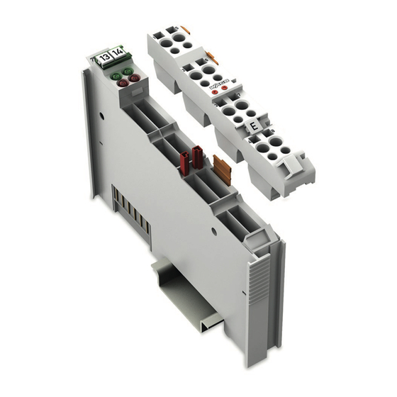
WAGO-I/O-SYSTEM 750 Device Description 753-461 2AI Pt 100/RTD View Depiction of the I/O module with 753-110 Plug! Information on this pluggable connection pertains to the 753-110 Plug, which is not included with the I/O module. Figure 1: View Table 4: Legend for Figure “View”... -
Page 18: Connectors
Device Description WAGO-I/O-SYSTEM 750 753-461 2AI Pt 100/RTD Connectors 3.2.1 Data Contacts/Local Bus Communication between the fieldbus coupler/controller and the I/O modules as well as the system supply of the I/O modules is carried out via the local bus. It is comprised of 6 data contacts, which are available as self-cleaning gold spring contacts. -
Page 19: Power Jumper Contacts/Field Supply
WAGO-I/O-SYSTEM 750 Device Description 753-461 2AI Pt 100/RTD 3.2.2 Power Jumper Contacts/Field Supply The I/O module 753-461 has no power jumper contacts. ® 3.2.3 CAGE CLAMP Connectors Depiction of the I/O module with 753-110 Plug! Information on this pluggable connection pertains to the 753-110 Plug, which is not included with the I/O module. - Page 20 Device Description WAGO-I/O-SYSTEM 750 753-461 2AI Pt 100/RTD Use shielded signal lines! Only use shielded signal lines for analog signals and I/O modules which are equipped with shield clamps. Only then can you ensure that the accuracy and interference immunity specified for the respective I/O module can be achieved even in the presence of interference acting on the signal cable.
-
Page 21: Display Elements
WAGO-I/O-SYSTEM 750 Device Description 753-461 2AI Pt 100/RTD Display Elements Figure 4: Display Elements Table 6: Legend for Figure “Display Elements” Channel LED State Function No operational readiness or the local bus communication is interrupted Operational readiness and trouble-free local bus... -
Page 22: Operating Elements
Device Description WAGO-I/O-SYSTEM 750 753-461 2AI Pt 100/RTD Operating Elements The I/O module 753-461 has no operating elements. Schematic Diagram Figure 5: Schematic Diagram Manual Version 1.3.1... -
Page 23: Technical Data
WAGO-I/O-SYSTEM 750 Device Description 753-461 2AI Pt 100/RTD Technical Data 3.6.1 Device Data Table 7: Technical Data — Device Width 12 mm Height (from top edge of DIN rail) 64 mm Depth 100 mm Weight Approx. 52.5 g 3.6.2 Power Supply Table 8: Technical Data –... -
Page 24: Climatic Environmental Conditions
Device Description WAGO-I/O-SYSTEM 750 753-461 2AI Pt 100/RTD 3.6.5 Climatic Environmental Conditions Table 11: Technical Data – Climatic Environmental Conditions Surrounding air temperature 0 °C … 55 °C (operation) Surrounding air temperature −20 °C … +60 °C (operation) for components with... -
Page 25: Approvals
Approvals More information about approvals. Detailed references to the approvals are listed in the document “Overview Approvals WAGO-I/O-SYSTEM 750”, which you can find via the internet under: www.wago.com > SERVICES > DOWNLOADS > Additional documentation and information on automation products > WAGO-I/O-SYSTEM 750 > System Description. - Page 26 Device Description WAGO-I/O-SYSTEM 750 753-461 2AI Pt 100/RTD The following ship approvals have been granted to the variations 753-461 listed below: 753-461 753-461 /003-000 ABS (American Bureau of Shipping) Federal Maritime and Hydrographic Agency BV (Bureau Veritas) DNV (Det Norske Veritas)
-
Page 27: Standards And Guidelines
WAGO-I/O-SYSTEM 750 Device Description 753-461 2AI Pt 100/RTD Standards and Guidelines All variations of 753-461 I/O modules meet the following requirements on emission and immunity of interference: EMC CE-Immunity to interference EN 61000-6-2 EMC CE-Emission of interference EN 61000-6-4 EMC marine applications-Immunity to interference acc. -
Page 28: Process Image
Process Image WAGO-I/O-SYSTEM 750 753-461 2AI Pt 100/RTD Process Image The I/O module transfers 16 bits per channel of measured data and, optionally, 8 status bits to the fieldbus coupler/controller. Access to the status bits depends on the specific fieldbus system. -
Page 29: I/O Module With Pt Resistance Sensors
WAGO-I/O-SYSTEM 750 Process Image 753-461 2AI Pt 100/RTD I/O Module with Pt Resistance Sensors Table 14: I/O Modules with Pt Resistance Sensors 753-461 Evaluation Pt100 Measuring range: −200 °C … +850 °C 4.1.1 Pt100 The 753-461 I/O module calculates the resistance measurement values from Pt100 sensors and outputs them as temperature values. -
Page 30: 753-461/003-000 Configurable I/O Module
Measuring range: −200 °C … +850 °C The operating mode of the 753-461/003-000 I/O module version can be configured using the free WAGO-I/O-CHECK startup tool. The default setting is Pt100. In this operating mode, the I/O module has the same behavior and process values as the 753-461 standard module. -
Page 31: Table 18: 753-461/003-000 I/O Module, Offset And Gain Values
WAGO-I/O-SYSTEM 750 Process Image 753-461 2AI Pt 100/RTD The following input fields are available in WAGO-I/O-CHECK for adjusting the offset and gain values for user and WAGO scaling: Table 18: 753-461/003-000 I/O Module, Offset and Gain Values Input field …... -
Page 32: Mounting
Don't forget the bus end module! Always plug a bus end module (750-600) onto the end of the fieldbus node! You must always use a bus end module at all fieldbus nodes with WAGO-I/O- SYSTEM 750 fieldbus couplers or controllers to guarantee proper data transfer. -
Page 33: Inserting And Removing Devices
WAGO-I/O-SYSTEM 750 Mounting 753-461 2AI Pt 100/RTD Inserting and Removing Devices Do not work when devices are energized! High voltage can cause electric shock or burns. Switch off all power to the device prior to performing any installation, repair or maintenance work. -
Page 34: Removing The I/O Module
Mounting WAGO-I/O-SYSTEM 750 753-461 2AI Pt 100/RTD 5.2.2 Removing the I/O Module Note Remove pluggable wiring! Before removing a 753 Series I/O Module from the node, you must first remove the plug (pluggable wiring) from the I/O module (see section “Plug Removal”)! -
Page 35: I/O Modules With Pluggable Wiring Level (Series 753)
WAGO-I/O-SYSTEM 750 Mounting 753-461 2AI Pt 100/RTD I/O Modules with Pluggable Wiring Level (Series 753) For wiring, a plug is plugged into the bottom of the module of all 753 Series I/O modules. The plug can be completely removed together with the wiring, simplifying replacement of defective modules from the assembly. -
Page 36: Coding
Mounting WAGO-I/O-SYSTEM 750 753-461 2AI Pt 100/RTD Figure 11: Attachment of Cable Binders 5.3.1 Coding Coding using small plastic pins and sockets facilitates mating of the I/O module with the appropriate plug. Insert the pin into the socket. Figure 12: Assembling the Coding Fingers Position the assembled coding fingers in the I/O module. -
Page 37: Figure 14: Plugging The Plug Into Place
WAGO-I/O-SYSTEM 750 Mounting 753-461 2AI Pt 100/RTD Figure 14: Plugging the Plug into Place When the plug is removed the sockets remain in the I/O module. The coded plug can only fit in the corresponding coded I/O module (see figures below). -
Page 38: Plug Removal
Mounting WAGO-I/O-SYSTEM 750 753-461 2AI Pt 100/RTD 5.3.2 Plug Removal Remove the plug from the I/O module by pulling the orange pull tab on the plug toward the top of the I/O module. Figure 16: Pulling the Pull Tab The plug detaches from the I/O module. -
Page 39: Connect Devices
Only one conductor may be connected to each CAGE CLAMP Do not connect more than one conductor at one single connection! If more than one conductor must be routed to one connection, these must be connected in an up-circuit wiring assembly, for example using WAGO feed- through terminals. ®... -
Page 40: Connection Examples
Connect Devices WAGO-I/O-SYSTEM 750 753-461 2AI Pt 100/RTD Connection Examples Use shielded signal lines! Only use shielded signal lines for analog signals and I/O modules which are equipped with shield clamps. Only then can you ensure that the accuracy and interference immunity specified for the respective I/O module can be achieved even in the presence of interference acting on the signal cable. -
Page 41: Rtd, 3-Wire Connection
WAGO-I/O-SYSTEM 750 Connect Devices 753-461 2AI Pt 100/RTD 6.2.2 2 × RTD, 3-Wire Connection Figure 21: Connection Example: 2 × RTD, 3-Wire Connection Manual Version 1.3.1... -
Page 42: Use In Hazardous Environments
WAGO-I/O-SYSTEM 750 753-461 2AI Pt 100/RTD Use in Hazardous Environments The WAGO-I/O-SYSTEM 750 (electrical equipment) is designed for use in Zone 2 hazardous areas and shall be used in accordance with the marking and installation regulations. The following sections include both the general identification of components (devices) and the installation regulations to be observed. -
Page 43: Marking Configuration Examples
WAGO-I/O-SYSTEM 750 Use in Hazardous Environments 753-461 2AI Pt 100/RTD Marking Configuration Examples 7.1.1 Marking for Europe According to ATEX and IECEx Figure 22: Marking Example According to ATEX and IECEx Figure 23: Text Detail – Marking Example According to ATEX and IECEx Manual Version 1.3.1... -
Page 44: Table 20: Description Of Marking Example According To Atex And Iecex
Use in Hazardous Environments WAGO-I/O-SYSTEM 750 753-461 2AI Pt 100/RTD Table 20: Description of Marking Example According to ATEX and IECEx Marking Description TUEV 07 ATEX 554086 X Approving authority resp. certificate numbers IECEx TUN 09.0001 X Dust Equipment group: All except mining... -
Page 45: Figure 24: Marking Example For Approved Ex I I/O Module According To
WAGO-I/O-SYSTEM 750 Use in Hazardous Environments 753-461 2AI Pt 100/RTD Figure 24: Marking Example for Approved Ex i I/O Module According to ATEX and IECEx Figure 25: Text Detail – Marking Example for Approved Ex i I/O Module According to ATEX and... -
Page 46: Table 21: Description Of Marking Example For Approved Ex I I/O Module According To Atex And Iecex
Use in Hazardous Environments WAGO-I/O-SYSTEM 750 753-461 2AI Pt 100/RTD Table 21: Description of Marking Example for Approved Ex i I/O Module According to ATEX and IECEx Marking Description TUEV 12 ATEX 106032 X Approving authority resp. certificate numbers IECEx TUN 12 0039 X... -
Page 47: Marking For The United States Of America (Nec) And Canada (Cec)
WAGO-I/O-SYSTEM 750 Use in Hazardous Environments 753-461 2AI Pt 100/RTD 7.1.2 Marking for the United States of America (NEC) and Canada (CEC) Figure 26: Marking Example According to NEC Figure 27: Text Detail – Marking Example According to NEC 500... -
Page 48: Figure 28: Text Detail - Marking Example For Approved Ex I I/O Module
Use in Hazardous Environments WAGO-I/O-SYSTEM 750 753-461 2AI Pt 100/RTD Figure 28: Text Detail – Marking Example for Approved Ex i I/O Module According to NEC 505 Table 23: Description of Marking Example for Approved Ex i I/O Module According to NEC 505... -
Page 49: Figure 30: Text Detail - Marking Example For Approved Ex I I/O Modules
WAGO-I/O-SYSTEM 750 Use in Hazardous Environments 753-461 2AI Pt 100/RTD Figure 30: Text Detail – Marking Example for Approved Ex i I/O Modules According to CEC 18 attachment J Table 25: Description of Marking Example for Approved Ex i I/O Modules According to CEC 18... -
Page 50: Installation Regulations
Special Notes Regarding Explosion Protection The following warning notices are to be posted in the immediately proximity of the WAGO-I/O-SYSTEM 750 (hereinafter “product”): WARNING – DO NOT REMOVE OR REPLACE FUSED WHILE ENERGIZED! WARNING – DO NOT DISCONNECT WHILE ENERGIZED! WARNING –... - Page 51 WAGO-I/O-SYSTEM 750 Use in Hazardous Environments 753-461 2AI Pt 100/RTD Explosive atmosphere occurring simultaneously with assembly, installation or repair work must be ruled out. Among other things, these include the following activities • Insertion and removal of components • Connecting or disconnecting from fieldbus, antenna, D-Sub, ETHERNET or...
-
Page 52: Special Notes Regarding Ansi/Isa Ex
Use in Hazardous Environments WAGO-I/O-SYSTEM 750 753-461 2AI Pt 100/RTD 7.2.2 Special Notes Regarding ANSI/ISA Ex For ANSI/ISA Ex acc. to UL File E198726, the following additional requirements apply: • Use in Class I, Division 2, Group A, B, C, D or non-hazardous areas only •... -
Page 53: List Of Figures
WAGO-I/O-SYSTEM 750 List of Figures 753-461 2AI Pt 100/RTD List of Figures Figure 1: View ...................... 17 Figure 2: Data Contacts ..................18 ® Figure 3: CAGE CLAMP Connectors ..............19 Figure 4: Display Elements .................. 21 Figure 5: Schematic Diagram ................22 Figure 6: Insert I/O Module (Example) .............. -
Page 54: List Of Tables
List of Tables WAGO-I/O-SYSTEM 750 753-461 2AI Pt 100/RTD List of Tables Table 1: Variants ....................5 Table 2: Number Notation ..................9 Table 3: Font Conventions ..................9 Table 4: Legend for Figure “View” ............... 17 ® Table 5: Legend for Figure “CAGE CLAMP Connectors”... - Page 55 WAGO-I/O-SYSTEM 750 753-461 2AI Pt 100/RTD Manual Version 1.3.1...
- Page 56 WAGO Kontakttechnik GmbH & Co. KG Postfach 2880 • D - 32385 Minden Hansastraße 27 • D - 32423 Minden Phone: +49 571 887 – 0 Fax: +49 571 887 – 844169 E-Mail: info@wago.com Internet: www.wago.com...
Need help?
Do you have a question about the WAGO-I/O-SYSTEM 750 and is the answer not in the manual?
Questions and answers