
Related Manuals for Lantronix PREMIERWAVE XC HSPA+


Summary of Contents for Lantronix PREMIERWAVE XC HSPA+
- Page 1 PremierWave XC HSPA+ Intelligent Gateway User Guide Part Number 900-678 Revision D February 2017...
-
Page 2: Intellectual Property
Technical Support Online: www.lantronix.com/support Sales Offices For a current list of our domestic and international sales offices, go to the Lantronix web site at www.lantronix.com/about/contact. Disclaimer All information contained herein is provided “AS IS.” Lantronix undertakes no obligation to update the information in this publication. Lantronix does not make, and specifically disclaims,... -
Page 3: Revision History
Revision History Date Rev. Comments October 2016 Updated document to firmware release 8.0.0.0R19. Changes include: Added Modbus, IPv6, and Initial Send content. Updated Flash and SNMP information. Removed Query Port content. May 2013 Initial document for firmware release 7.7.0.0R27. April 2014 Updated document to firmware release 7.8.0.0. -
Page 4: Table Of Contents
Table of Contents Intellectual Property ________________________________________________________ 2 Warranty _________________________________________________________________ 2 Contacts _________________________________________________________________ 2 Disclaimer ________________________________________________________________ 2 Revision History ___________________________________________________________ 3 List of Figures ____________________________________________________________ 11 List of Tables _____________________________________________________________ 12 1: Using This Guide Purpose and Audience _____________________________________________________ 15 Summary of Chapters ______________________________________________________ 15 Additional Documentation ___________________________________________________ 16 2: Introduction Key Features _____________________________________________________________ 17... - Page 5 5: Configuration Using Web Manager Accessing Web Manager ___________________________________________________ 32 Device Status Page ________________________________________________________ 33 Web Manager Components _________________________________________________ 34 Navigating Web Manager ___________________________________________________ 35 6: Network Settings Network 1 Status __________________________________________________________ 38 Network 1 (eth0) Interface Settings ____________________________________________ 38 To Configure Network 1 Interface Settings ___________________________________ 40 Network 1 (eth0) Link Settings _______________________________________________41 To Configure Network 1 Link Settings ______________________________________ 41...
- Page 6 To Configure VPN Settings ______________________________________________ 56 GRE Settings ____________________________________________________________ 56 To Configure Tunnel Serial Settings ________________________________________ 57 7: Cellular To Configure Cellular Settings ____________________________________________ 58 Typical Cellular Error (errcodes) ______________________________________________ 59 8: Input/Output Ports Relay Output _____________________________________________________________ 60 To Configure Relay Settings ______________________________________________ 60 Digital Input ______________________________________________________________ 61 To Configure Digital Input Settings _________________________________________ 61 9: Action Settings...
- Page 7 Modem Emulation ______________________________________________________ 80 To Configure Tunnel Modem Emulation Settings ______________________________ 81 11: Terminal and Host Settings Terminal Settings _________________________________________________________ 82 To Configure the Terminal Network Connection _______________________________ 83 To Configure the Terminal Line Connection __________________________________ 83 Host Configuration ________________________________________________________ 83 To Configure Host Settings ______________________________________________ 84 12: Network Services DNS Settings _____________________________________________________________ 85...
- Page 8 15: Security Settings Public Key Infrastructure ____________________________________________________ 99 TLS (SSL) _______________________________________________________________ 99 Digital Certificates ________________________________________________________ 100 Trusted Authorities _______________________________________________________ 100 Obtaining Certificates _____________________________________________________ 100 Self-Signed Certificates ____________________________________________________ 100 Certificate Formats _______________________________________________________ 100 OpenSSL _______________________________________________________________ 101 SSH Settings ____________________________________________________________ 101 SSH Server Host Keys _________________________________________________ 101 SSH Client Known Hosts _______________________________________________ 102 SSH Server Authorized Users ___________________________________________ 102 SSH Client Users _____________________________________________________ 103...
- Page 9 To View Hardware Information ___________________________________________ 114 IP Sockets __________________________________________________________ 114 To View the List of IP Sockets ___________________________________________ 114 Ping _______________________________________________________________ 114 To Ping a Remote Host ________________________________________________ 115 Traceroute __________________________________________________________ 115 To Perform a Traceroute _______________________________________________ 115 Log ________________________________________________________________ 116 To Configure the Diagnostic Log Output ___________________________________ 116 Memory _____________________________________________________________ 116 To View Memory Usage ________________________________________________ 116...
- Page 10 Software _______________________________________________________________ 130 Power _________________________________________________________________ 131 Environmental ___________________________________________________________ 131 Dimensions _____________________________________________________________ 131 Appendix B: Compliance Appendix C: Lantronix Technical Support Appendix D: Binary to Hexadecimal Conversions Converting Binary to Hexadecimal ___________________________________________ 136 Conversion Table _____________________________________________________ 136 Scientific Calculator ___________________________________________________ 136...
-
Page 11: List Of Figures
List of Figures Figure 2-1 PremierWave Unit Product Label ___________________________________________ 20 Figure 3-1 PremierWave XC HSPA+ Unit______________________________________________ 22 Figure 3-5 PremierWave XC HSPA+ Male DB9 DTE Serial Ports ___________________________ 24 Figure 3-6 PremierWave XC HSPA+ Pinout Configuration for RS-232 _______________________ 24 Figure 3-7 PremierWave XC HSPA+ Pinout Configuration for Full Duplex RS-422/485 (4-wire) ____ 25 Figure 3-8 PremierWave XC HSPA+ Pinout Configuration for Half Duplex RS-422/485 (2-wire) ___ 25 Figure 3-11 PremierWave XC HSPA+ Bottom/Back Panel View ____________________________ 26... - Page 12 List of Tables Table 3-2 PremierWave XC HSPA+ LEDs and Descriptions _______________________________ 22 Table 3-3 Fault Conditions Indicated by Blink Patterns ___________________________________ 23 Table 3-4 Cellular Signal Strength Indicator ___________________________________________ 23 Table 3-9 Left Ethernet LED _______________________________________________________ 25 Table 3-10 Right Ethernet LED _____________________________________________________ 25 Table 3-12 PremierWave XC HSPA+ Connections (Side) _________________________________ 26 Table 5-3 Web Manager Pages ____________________________________________________ 35 Table 6-1 Network Interface Settings _________________________________________________ 38...
- Page 13 Table 10-1 Line Configuration Settings _______________________________________________68 Table 10-2 Line Command Mode Settings _____________________________________________ 69 Table 10-3 Tunnel Serial Settings ___________________________________________________ 70 Table 10-4 Tunnel Packing Mode Settings ____________________________________________ 71 Table 10-5 Tunnel Accept Mode Settings _____________________________________________ 73 Table 10-6 Tunnel Connect Mode Settings ____________________________________________ 76 Table 10-7 Tunnel Disconnect Mode Settings __________________________________________ 79 Table 10-8 Tunnel Modem Emulation Settings _________________________________________ 80 Table 11-1 Terminal on Network and Line Settings ______________________________________ 82...
-
Page 14: Premierwave® Xc Hspa+ Intelligent Gateway User Guide
Table 16-7 ARP Protocol Stack Settings _____________________________________________ 113 Table 16-8 Ping Settings _________________________________________________________ 114 Table 16-9 Traceroute Settings ____________________________________________________ 115 Table 16-10 Log Settings _________________________________________________________ 116 Table 16-11 Clock Settings _______________________________________________________ 118 Table 16-12 System Settings ______________________________________________________ 119 Table 17-1 CLI Configuration Settings _______________________________________________ 120 Table 17-2 Telnet Settings _______________________________________________________ 121 Table 17-3 SSH Settings _________________________________________________________ 121 Table 17-4 XML Exporting Configuration _____________________________________________ 122... -
Page 15: 1: Using This Guide
Using This Guide Purpose and Audience This guide provides the information needed to configure, use, and update the Lantronix® PremierWave® XC HSPA+ intelligent gateway. It is intended for software developers and system integrators who are installing this product into their designs. -
Page 16: Additional Documentation
1: Using This Guide Additional Documentation Visit the Lantronix Web site at www.lantronix.com/support/documentation for the latest documentation and the following additional documentation. Document Description PremierWave XC HSPA+ Instructions for accessing Command Mode (the command line Intelligent Gateway Command interface) using a Telnet connection, SSH connection or through the Reference port. -
Page 17: 2: Introduction
Introduction The PremierWave XC HSPA+ intelligent gateway is an industrial grade GSM/GPRS 3.5G cellular solution that enables customers to quickly connect their machines and assets for out-of-the-box Internet access, remote monitoring, control and cloud platform connectivity. With highly configurable and easy to use software offering enterprise level security, the PremierWave XC HSPA+ intelligent gateway makes it possible to combine multiple application use cases in a compact, ruggedized platform. -
Page 18: Applications
2: Introduction Industrial Grade Temperature Range: Operating temperature at -40°C to +70°C. Storage temperature at - 40°C to +85°C Wide Voltage Range: 9 - 30VDC input voltage through locking barrel connector Flexible Connectivity Options Serial Ports: Two RS-232/422/485 ports with support from 300 to 921 kbps data rate ... -
Page 19: Troubleshooting Capabilities
The hardware address is also referred to as the Ethernet address, physical address, or MAC address. The first three bytes of the Ethernet address are fixed and identify the unit as a Lantronix product. The fourth, fifth, and sixth bytes are unique numbers assigned to each unit. Sample hardware address: ... -
Page 20: Ip Address
TCP Port 80: HTTP (Web Manager Configuration) TCP Port 21: FTP UDP Port 30718: LDP (Lantronix Discovery Protocol) port TCP/UDP Port 10001: Tunnel 1 (see note below) UDP Port 1900 and TCP Port 30179: UPnP ... -
Page 21: 3: Installation Of The Premierwave Xc Hspa+ Device
Installation of the PremierWave XC HSPA+ Device This chapter describes how to install the PremierWave XC HSPA+ intelligent gateway. It contains the following sections: Package Contents User-Supplied Items Hardware Components Installing the PremierWave XC HSPA+ Unit Device ... -
Page 22: Hardware Components
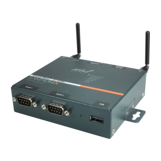
3: Installation of the PremierWave XC HSPA+ Device Hardware Components Front/Top Panel Figure 3-1 shows the top panel view of the PremierWave unit. Table 3-2, Table 3-3, and Table 3-4 list and explain the behavior of the LEDs on the top panel. LED Indicators: 1 Power LED, 2 Serial Activity LEDs, 1 USB LED, 1 Cellular Status LED, 5 Signal Strength LEDs (two of which are dual-colored), 1 Diagnostic LED, and 2 Ethernet LEDs (on the RJ45 port). -
Page 23: Table 3-3 Fault Conditions Indicated By Blink Patterns
3: Installation of the PremierWave XC HSPA+ Device Table 3-3 Fault Conditions Indicated by Blink Patterns Note: The fault LED blink patterns in this table are listed in order of priority. Fault Conditions Blink Pattern No Ethernet link when eth0 (Ethernet Network) is Long, long, short, short, 2 seconds off enabled. -
Page 24: Figure 3-5 Premierwave Xc Hspa+ Male Db9 Dte Serial Ports
3: Installation of the PremierWave XC HSPA+ Device The PremierWave device has two male DB9 serial ports that support RS-232/422/485. Figure 3-5 shows the front view of the device. The default serial port settings are 9600 baud, 8 bits, no parity, 1 stop bit, no flow control. -
Page 25: Figure 3-7 Premierwave Xc Hspa+ Pinout Configuration For Full Duplex Rs-422/485 (4-Wire)
3: Installation of the PremierWave XC HSPA+ Device Figure 3-7 PremierWave XC HSPA+ Pinout Configuration for Full Duplex RS-422/485 (4-wire) Figure 3-8 PremierWave XC HSPA+ Pinout Configuration for Half Duplex RS-422/485 (2-wire) Ethernet LEDs The Ethernet port (see Figure 3-11) has two LEDs that indicate the status of the connection as described in the Table 3-9 Table 3-10... -
Page 26: Back Panel
3: Installation of the PremierWave XC HSPA+ Device 2. Remove the paper clip to release the button. The unit will continue the boot process restoring it back to the original factory default settings. Back Panel On the PremierWave device is a Power Connector and RJ-45 Ethernet port as shown in Figure 3-11. -
Page 27: Figure 3-13 Sim Card Insertion
3: Installation of the PremierWave XC HSPA+ Device Note: As soon as you plug the device into power, the device powers up automatically, the self-test begins, and LEDs would indicate the device's status Perform the following steps to install your device: 1. -
Page 28: Figure 3-14 Premierwave Xc Hspa+ Unit Dimensions In Inches (In)
3: Installation of the PremierWave XC HSPA+ Device Figure 3-14 PremierWave XC HSPA+ Unit Dimensions in Inches (in) PremierWave® XC HSPA+ Intelligent Gateway User Guide... -
Page 29: 4: Device Discovery And Quick Setup
UPnP (Network Discovery) on Windows XP and Windows 7 operating systems. To search devices on Windows XP operating system: 1. Click Start->My Network Places. Lantronix PremierWave XC HSPA+ devices will be listed like other network devices. 2. Double-click your device to view the device web page. -
Page 30: Accessing The Premierwave Xc Hspa+ Device Using Deviceinstaller
1. Run the executable to start the installation process and respond to the installation wizard prompts. (If prompted to select an installation type, select Typical.) 2. Click Start -> All Programs -> Lantronix -> DeviceInstaller 4.4 -> DeviceInstaller. 3. When DeviceInstaller starts, it will perform a network device search. To perform another search, click Search. - Page 31 Shows the device family type as “PremierWave”. Short Name Shows ”premierwave_xc_hspa” by default. Long Name Shows “Lantronix PremierWave XC HSPA+” by default. Type Shows the device type as “PremierWave XC HSPA+”. Shows the PremierWave ID embedded within the unit. Hardware Address Shows the PremierWave hardware (MAC) address.
-
Page 32: 5: Configuration Using Web Manager
DeviceInstaller application window. To access Web Manager, perform the following steps: 1. Open a standard web browser. Lantronix supports the latest versions of Internet Explorer, Mozilla Firefox, Safari or Chrome web browsers. 2. Enter the IP address or hostname of the PremierWave XC HSPA+ unit in the address bar. The IP address may have been assigned manually using DeviceInstaller (see the PremierWave XC HSPA+ Intelligent Gateway Quick Start Guide) or automatically by DHCP. -
Page 33: Device Status Page
5: Configuration Using Web Manager Device Status Page The Device Status page is the first to appear after you log into Web Manager. The Device Status page also appears when you click Status in Web Manager. Figure 5-1 Device Status Page PremierWave®... -
Page 34: Web Manager Components
5: Configuration Using Web Manager Web Manager Components The layout of a typical Web Manager page is below. Figure 5-2 Components of the Web Manager Page Logout Items to Links to button configure subpages Header Menu Bar Footer Information Configuration and/or Status Area and Help Area Web Manager pages have these sections: The menu bar always appears at the left side of the page regardless of the page shown. -
Page 35: Navigating Web Manager
The footer appears at the very bottom of the page. It contains copyright information and a link to the Lantronix home page. Navigating Web Manager The Web Manager provides an intuitive point-and-click interface. A menu bar on the left side of each page provides links you can click to navigate from one page to another. - Page 36 5: Configuration Using Web Manager Web Manager Page Description (continued) Page Discovery Allows you to view and modify the configuration and statistics for device discovery. DDNS Alllows you to view and configure DDNS settings. Shows the current configuration of the DNS subsystem and the DNS cache.
- Page 37 5: Configuration Using Web Manager Web Manager Page Description (continued) Page Lets you export XML configuration and status records, and import XML configuration records. PremierWave® XC HSPA+ Intelligent Gateway User Guide...
-
Page 38: 6: Network Settings
Network Settings The Network Settings show the status of the network device interface/link and lets you configure the settings on the device. Interface settings are related to the configuration of the IP and related protocols. Link settings are related to the physical link connection, which carries the IP traffic. The PremierWave XC HSPA+ contains one Ethernet and one Cellular interface.The Ethernet interface is called Network 1 or eth0, and the Cellular interface is also called Network 2 or wwan0. - Page 39 6: Network Settings Network Interface Description Settings (continued) BOOTP Client Select to turn On or Off. At boot up, after the physical link is up, the PremierWave device will attempt to obtain IPv4 settings from a BOOTP server. Note: Overrides the configured IPv4 address/mask, gateway, hostname, and domain.
-
Page 40: To Configure Network 1 Interface Settings
6: Network Settings Network Interface Description Settings (continued) IPv6 State Select to enable of disable the IPv4 state. IPv6 DHCP Client Select to turn On or Off. On: will provide an additional IPv6 address in addition to the displayed Link ... -
Page 41: Network 1 (Eth0) Link Settings
6: Network Settings Network 1 (eth0) Link Settings Physical link parameters can be configured for an Ethernet (eth0) Network Link (see Table 6-2). Table 6-2 Network 1 (eth0) Link Settings Network 1 Ethernet (eth0) Description Link Settings Select the Ethernet link speed. (Default is Auto) Auto = Auto-negotiation of Link Speed ... -
Page 42: To Configure Network 1 Qos Settings
6: Network Settings Move bandwidth allocation is a minimum 5% each to Network control. Voice: Bandwidth allocation is minimum 30%. Video: Bandwidth allocation is minimum 20%. Critical Applications: Bandwidth allocation is minimum 15%. Excellent Effort: Bandwidth allocation is minimum 10%. ... -
Page 43: Network 1 (Eth0) Failover
6: Network Settings Using the CLI To enter the eth0 QoS command level: enable -> config -> if 1 -> qos Using XML Include in your file: <configgroup name="qos" instance="eth0"> Network 1 (eth0) Failover The PremierWave XC HSPA+ intelligent gateway provides Cellular WAN network failover, in the form of a "dead remote host reachability"... -
Page 44: Network 2 Status
6: Network Settings Network 2 Status In the Network 2 status pages, you can view both the current interface operational settings as well as the settings that would take effect upon a device reboot, as well as Link, QoS and Failover status information. -
Page 45: To Configure Network 2 Interface Settings
6: Network Settings To Configure Network 2 Interface Settings Using Web Manager To modify network 2 wwan0 interface information, click Network on the menu and select Network 2 > Interface > Configuration. Using the CLI To enter the cellular command level: enable -> config -> if 2 ... -
Page 46: Network 2 (Cellular "Wwan0") Qos
6: Network Settings Network 2 (Cellular “wwan0”) QoS QoS (Quality of Service) can be enabled and configured for both Network 1 (eth0) and Network 2 (wwan0). If enabled, the router will control the flow of outbound traffic according to the user- defined filters. -
Page 47: To Configure Network 2 Qos Settings
6: Network Settings To Configure Network 2 QoS Settings Using Web Manager To modify Ethernet (eth0) QoS information, click Network on the menu and select Network 2 > QoS > Configuration. Using the CLI To enter the eth0 QoS command level: enable -> config -> if 2 -> qos ... -
Page 48: Wan Mac Address Filters
6: Network Settings Gateway Settings Description Secondary DNS Enter the IP address of the secondary Domain Name Server. Note: This setting will be used when either Static IP or Auto IP is active, or if DHCP/BOOTP is active and no DNS server was acquired from the server. -
Page 49: To Configure Gateway Port Forwarding Settings
6: Network Settings Table 6-12 Port Forwarding Rules List Port Forwarding Rule Description Enabled Enables the port forwarding rule. Delete Deletes the port forwarding rule. Name User friendly name for the rule. Click on the [Edit] icon to make changes. Ingress IP Address: Port Port or Port range for the rule. -
Page 50: To Configure Gateway Static Route Settings
6: Network Settings Table 6-15 Adding a New Static Route Adding New Static Route Description Settings Name Enter the user friendly name for the route. Network Enter the Network or Host for the route. Gateway Enter the Gateway for the route. Interface Select the Interface for the route. -
Page 51: To Configure Gateway Dhcp Server Settings
6: Network Settings To Configure Gateway DHCP Server Settings Using Web Manager To modify gateway DHCP server information, click Gateway on the menu and select Configuration > DHCP Server. Using the CLI To enter the gateway command level: enable -> config -> gateway -> dhcp ... -
Page 52: To Configure Gateway Routing Protocol Settings
6: Network Settings Table 6-19 Routing Protocol Settings Routing Settings Description State (RIP) Select to enable or disable the RIP state. Version Select how the RIP is to be configured. It can accept Version 1, Version 2, or Version 1 and 2. Update Interval Indicate the number of seconds for the Update Interval. -
Page 53: To Configure Gateway Virtual Ip
6: Network Settings Virtual IP Settings Description Delete (checkbox) Check the Delete checkbox adjacent to a virtual IP address to be deleted, clicking the Submit button. Name The name of an existing virtual IP address. IP Address An existing virtual IP address to which the LAN IP address is to be mapped. LAN IP Address An existing LAN IP address to which the virtual IP address is to be mapped. -
Page 54: To Configure Gateway Wan Settings
6: Network Settings To Configure Gateway WAN Settings Using Web Manager To view or configure DDNS information, click DDNS in the menu. Using the CLI To enter the gateway command level: enable -> config -> ddns Using XML Not any. - Page 55 6: Network Settings VPN Settings Description Mode Configuration Click to enable or disable extended authentication operation and the settings provided to the client during the configuration exchange. Type Select the VPN type: Tunnel - Tunnel mode is used for protecting traffic between networks, ...
-
Page 56: To Configure Vpn Settings
6: Network Settings VPN Settings Description Unreachable Host Detection Host Enter the Host to use failover host and ping interval to monitor connectivity with a host on the remote network. Ping Interval Indicate the ping interval, in minutes, to use failover host and ping interval to monitor connectivity with a host on the remote network. -
Page 57: To Configure Tunnel Serial Settings
6: Network Settings To Configure Tunnel Serial Settings Using Web Manager To configure the GRE for a specific tunnel, click GRE. Using the CLI To enter GRE command level: enable -> gre Using XML Include in your file: <configgroup name=”gre”> ... -
Page 58: 7: Cellular
Cellular The Cellular page displays the configuration and status for the Cellular module. Cellular Settings Description PIN Lock Enable to prevent unauthorized use of the SIM card. Enter PIN combination to enable PIN Lock. Caution: If you enter the PIN incorrectly 3 times, the SIM card will lock, and you will need a PIN Unblocking Key (PUK) to unlock your SIM card. -
Page 59: Typical Cellular Error (Errcodes)
7: Cellular Typical Cellular Error (errcodes) The following is a list of common errors that may appear in the Cellular module. PH-SIM PIN required SIM failure PH-FSIM PIN required SIM busy PH-FSIM PUK required SIM wrong ... -
Page 60: 8: Input/Output Ports
Input/Output Ports Relay Output Note: When the relay is energized/turned on, the relay is closed, connecting both relay ports on the I/O connector through the relay. When the relay is turned off, the signal path is open, disconnecting the relay ports on the I/O connector. Table 8-1 Relay Output Settings Relay Output Description... -
Page 61: Digital Input
8: Input/Output Ports Digital Input Table 8-2 contains additional configuration options for Digital Input 1 and Digital Input 2 settings: Table 8-2 Digital Input Settings Digital Input Settings Description State This field is found in the Digital Input Status page. Indicates state of the digital input. -
Page 62: 9: Action Settings
Action Settings Actions can be configured for alarms and reports available in the PremierWave XC HSPA+ intelligent gateway. Alarms and Reports PremierWave XC HSPA+ intelligent gateway updates the action settings page to display and configure the alarms. The following alarm and report actions are available in PremierWave XC HSPA+ device: eth0 link state change ... -
Page 63: To Configure Action Settings
9: Action Settings Action Settings Description FTP Put Use FTP Put to put a file on configured FTP server. Filename will be used to upload to remote FTP server. The IP Address or hostname is the FTP server to connect. Port number is port on which FTP server is listening on. Use Protocol to connect to FTP server. -
Page 64: Python
Python™ is a dynamic, object-oriented programming language that can be used for developing a wide range of software applications. The Lantronix PremierWave HSPA+ includes the installation of Python interpreter, making it easy to load and run custom Python scripts on your intelligent gateway. -
Page 65: Applications
9: Action Settings PyNPP: https://github.com/mpcabd/PyNPP This plugin allows the user to use keystrokes to launch the open Python script in the local Python interpreter for debugging and testing. NppFTP: http://sourceforge.net/projects/nppftp/ This plugin provides a one-click upload of a file to an FTP server. Debugging and testing on the PremierWave platform easier because PremierWave products have an FTP server through which to upload files into the file system. -
Page 66: To Configure Application Settings
9: Action Settings Script Settings Description Filename Enter the package file name pathway in the file system and click the Install button to install it. To Configure Application Settings Using Web Manager To configure application scripts, click Applications on the menu. ... -
Page 67: 10: Line And Tunnel Settings
10: Line and Tunnel Settings The PremierWave XC HSPA+ intelligent gateway has two tunnels through which you may view statistics or configure the Accept Mode. The PremierWave XC HSPA+ intelligent gateway contains two serial lines. All lines use standard RS232/RS485 serial ports. All lines can be configured to operate in the following modes: RS232 ... -
Page 68: Table 10-1 Line Configuration Settings
10: Line and Tunnel Settings Using XML Include in your file: <statusgroup name=”line” instance=”1”> The Line Settings allow configuration of the serial lines (ports). Table 10-1 Line Configuration Settings Line Settings Description Enter a name or short description for the line, if desired. By default, there is Name no name specified. -
Page 69: To Configure Line Command Mode
10: Line and Tunnel Settings Table 10-2 Line Command Mode Settings Line Command Description Mode Settings Set the Command Mode state of the Line. When in Command Mode, a CLI session operates exclusively on the Line. Choices are: Always User Serial String ... -
Page 70: Tunnel Statistics
10: Line and Tunnel Settings Tunnel Statistics Tunnel statistics contains data counters, error counters, connection time and connection information. Statistics are available at each individual connection and aggregated across all connections. Note: The following section describes the steps to view Tunnel 1 statistics; these steps apply to other tunnel instances of the device. -
Page 71: To Configure Tunnel Serial Settings
10: Line and Tunnel Settings Tunnel Serial Description Settings (continued) Select the conditions under which the Data Terminal Ready (DTR) control signal on the serial line is asserted. Choices are: Unasserted TruPort = the DTR is asserted whenever either a connect or an accept ... -
Page 72: To Configure Tunnel Packing Mode Settings
10: Line and Tunnel Settings Tunnel Packing Description Mode Settings Enter Control Characters in any of the following forms: <control>J 0xA (hexadecimal) Send Character \10 (decimal) If used, the Send Character is a single printable character or a control character that, when read on the Serial Line, forces the queued data to be sent on the network immediately. -
Page 73: Table 10-5 Tunnel Accept Mode Settings
10: Line and Tunnel Settings Table 10-5 Tunnel Accept Mode Settings Tunnel Accept Mode Description Settings Set the method used to start a tunnel in Accept mode. Choices are: Disable = do not accept an incoming connection. Always = accept an incoming connection (default). ... - Page 74 10: Line and Tunnel Settings Tunnel Accept Mode Description Settings (continued) Initial Send Enter the Initial Send string indicating whether it is in Text or Binary form. This Initial Send data will be sent out to the network upon connection establishment, before any data, from the Line.
-
Page 75: To Configure Tunnel Accept Mode Settings
10: Line and Tunnel Settings To Configure Tunnel Accept Mode Settings Using Web Manager To configure the Accept Mode for a specific tunnel, click Tunnel in the menu and select Tunnel 1 -> Accept Mode. Using the CLI To enter Tunnel 1 Accept Mode command level: enable -> tunnel 1 -> accept ... - Page 76 10: Line and Tunnel Settings Tunnel Connect Mode Description Settings (continued) Click on the displayed information to expand it for editing. If <None> is displayed, clicking it will allow you to configure a new host. At least one Host is required to enable Connect Mode as this information is necessary to connect to that host.
-
Page 77: Connecting Multiple Hosts
10: Line and Tunnel Settings Tunnel Connect Mode Description Settings (continued) Set the value of the reconnect timeout (in milliseconds) for outgoing connections Reconnect Timer established by the device. Valid range is 1 to 65535 milliseconds. Default is 15000. Set whether the serial Line data buffer is flushed upon a new network connection. -
Page 78: Host List Promotion
10: Line and Tunnel Settings Simultaneous – A tunnel will connect to all hosts accepting a connection. Simultaneous connections occur at the same time to all listed hosts. The device can support a maximum of 64 total aggregate connections. Host List Promotion This feature allows Host IP promotion of individual hosts in the overall sequence. -
Page 79: Modem Emulation
10: Line and Tunnel Settings Using XML Include in your file: <configgroup name=”tunnel disconnect” instance=”1”> Modem Emulation Some older equipment is designed to attach to a serial port and dial into a network with a modem. This equipment uses AT commands to control the connection. For compatibility with these older devices on modern networks, the PremierWave device mimics the behavior of the modem. -
Page 80: To Configure Tunnel Modem Emulation Settings
10: Line and Tunnel Settings To Configure Tunnel Modem Emulation Settings Using Web Manager To configure the Modem Emulation for a specific tunnel, click Tunnel in the menu and select Tunnel 1 -> Modem Emulation. Using the CLI To enter the Tunnel 1 Modem command level: enable -> tunnel 1 -> modem ... -
Page 81: 11: Terminal And Host Settings
11: Terminal and Host Settings Predefined connections are available via Telnet, SSH, or a serial port. A user can choose one of the presented options and the device automatically makes the predefined connection. Either the Telnet, SSH, or serial port connection can present the CLI or the Login Connect Menu. By default, the CLI is presented when the device is accessed. -
Page 82: To Configure The Terminal Network Connection
11: Terminal and Host Settings To Configure the Terminal Network Connection Using Web Manager To configure the Terminal on Network, click Terminal on the menu and select Network -> Configuration. Using the CLI To enter the Terminal Network command level: enable -> config -> terminal ... -
Page 83: To Configure Host Settings
11: Terminal and Host Settings Host Settings Description SSH Username Appears if you selected SSH as the protocol. Enter a username to select a pre- configured Username/Password/Key (configured on the SSH: Client Users page), or leave it blank to be prompted for a username and password at connect time. Note: This configuration option is only available when SSH is selected for Protocol. -
Page 84: 12: Network Services
12: Network Services DNS Settings This section describes the active run-time settings for the domain name system (DNS) protocol. The primary and secondary DNS addresses come from the active interface. The static addresses from the Network Interface configuration settings may be overridden by DHCP. Note: blue text in the XML command strings of this chapter are to be replaced with... -
Page 85: Ftp Settings
12: Network Services FTP Settings The FTP protocol can be used to upload and download user files, and upgrade the PremierWave XC HSPA+ intelligent gateway firmware. A configurable option is provided to enable or disable access via this protocol. FTP Settings Table 12-2 FTP Settings Description... -
Page 86: To View Or Configure Syslog Settings
12: Network Services Syslog Settings Description (continued) Specify the minimum level of system message the PremierWave device should log by selecting from the drop-down menu. This setting applies to all syslog facilities. Severity Log Level The drop-down list in the Web Manager is in descending order of severity (e.g., Emergency is more severe than Alert.) To View or Configure Syslog Settings Using Web Manager... -
Page 87: To Configure Http Settings
12: Network Services HTTP Settings (continued) Description Max Timeout Enter the maximum time for the HTTP server to wait when receiving a request. This prevents Denial-of-Service (DoS) attacks. The default is 10 seconds. Max Bytes Enter the maximum number of bytes the HTTP server accepts when receiving a request. -
Page 88: To Configure Http Authentication
12: Network Services HTTP Authentication Settings Table 12-5 HTTP Authentication Description Settings Enter the Uniform Resource Identifier (URI). Note: The URI must begin with ‘/’ to refer to the filesystem. Auth Type Select the authentication type: None = no authentication is necessary. ... -
Page 89: To Configure Rss Settings
Specify a system location for the SNMP setting. Lantronix MIB File Click the Lantronix MIB file name to save and load it into the MIB browser and trap receiver. This is the base MIB file for Lantronix products. Load or compile this file first. -
Page 90: Discovery
12: Network Services Using Web Manager To configure SNMP, click SNMP in the menu. Using the CLI To enter the SNMP command level: enable -> config -> snmp Using XML Include in your file: <configgroup name=”snmp”> Discovery The current statistics and configuration options for device discovery, including UPnP query port are available for the PremierWave XC HSPA+ intelligent gateway. -
Page 91: Smtp Settings
12: Network Services SMTP Settings Table 12-9 SMTP Settings SMTP Settings Description From Address Enter the From Address here. This is an email address and is required. If you wish to direct oubtound email messages through a mail server, put your client email address here. -
Page 92: To View, Configure, And Send Email
12: Network Services Email – Configuration Description Settings (continued) Message File Enter the path of the file to send with the email alert. This file appears within the message body of the email, not as an attachment. Priority Select the priority level for the email alert: Urgent ... -
Page 93: 13: Sms Settings
13: SMS Settings SMS settings allows the user to view and configure inbound/outbound SMS to/from the device. Adding a number to the SMS whitelist allows the SMS from the number to trigger one or more control functions on the device. The following control functions are available: Shoulder-Tap function can be used to bring up the cellular connection. -
Page 94: To Configure Inbound Sms
13: SMS Settings Outbound SMS Settings Description Number Enter the Recipient Number. Encoding Select the SMS encoding mode: ASCII 7-bit ASCII 8-bit UCS-2 Message Enter the SMS message content. Note: Entering more than 70 characters in the SMS message may cause splitting of text messages. -
Page 95: 14: Updating Firmware
14: Updating Firmware Obtaining Firmware Obtain the most up-to-date firmware and release notes for the unit from the Lantronix Web site (www.lantronix.com/support/downloads/) or by using anonymous FTP (ftp://ftp.lantronix.com/). Loading New Firmware through Web Manager Upload the firmware using the device web manager System page. -
Page 96: Figure 14-1 Uploading New Firmware
14: Updating Firmware Figure 14-1 Uploading New Firmware 2. Click Browse (under the Upload New Firmware heading) to browse to the firmware file. 3. Select the file and click Open. 4. Click Upload to install the firmware on the PremierWave XC HSPA+ unit. 5. -
Page 97: Loading New Firmware Through Ftp
14: Updating Firmware Loading New Firmware through FTP Firmware may be updated by sending the file to the PremierWave XC HSPA+ intelligent gateway over an FTP connection. The destination file name on the PremierWave XC HSPA+ unit must have a "firmware.rom" type of format. The device will reboot upon successful completion of the firmware upgrade. -
Page 98: 15: Security Settings
15: Security Settings The PremierWave XC HSPA+ device supports Secure Shell (SSH) and Secure Sockets Layer (SSL). SSH is a network protocol for securely accessing a remote device. SSH provides a secure, encrypted communication channel between two hosts over a network. It provides authentication and message integrity services. -
Page 99: Digital Certificates
15: Security Settings Digital Certificates The goal of a certificate is to authenticate its sender. It is analogous to a paper document that contains personal identification information and is signed by an authority, for example a notary or government agency. With digital certificates, a cryptographic key is used to create a unique digital signature. -
Page 100: Openssl
15: Security Settings OpenSSL OpenSSL is a widely used open source set of SSL related command line utilities. It can act as server or client. It can also generate or sign certificate requests, and can convert from and to several different of formats. OpenSSL is available in binary form for Linux and Windows. -
Page 101: Ssh Client Known Hosts
15: Security Settings SSH Settings Description (continued) Public Key Click Choose File to browse to and select the existing public key you want to upload. In Web Manager, you can also browse to the public key to be uploaded. Key Type Select a key type to use for the new key: ... -
Page 102: Ssh Client Users
15: Security Settings Table 15-3 SSH Server Authorized Users SSH Settings Description Username Enter a new username or edit an existing one. Password Enter a new password or edit an existing one. Public RSA Key Click Choose File to browse to and select the existing public RSA key you want to use with this user. -
Page 103: To Configure Ssh Settings
15: Security Settings SSH Settings Description (continued) Add/Edit (button) Click the Add/Edit button after completing the Username, Password, and Remote Command fields above, and selecting the key and key type. Table 15-5 Create New Keys SSH Settings Description Username Enter the name that the device uses to connect to an SSH server. Key Type Select a bit length for the key: ... -
Page 104: Ssl Settings
15: Security Settings SSL Settings Secure Sockets Layer (SSL) is a protocol for managing the security of data transmission over the Internet. It provides encryption, authentication, and message integrity services. SSL is widely used for secure communication to a web server. Certificate/Private key combinations can be obtained from an external Certificate Authority (CA) and uploaded into the unit. -
Page 105: Upload Certificate
15: Security Settings Upload Certificate SSL certificates identify the PremierWave XC HSPA+ intelligent gateway to peers. Certificate and key pairs can be uploaded to the PremierWave XC HSPA+ unit through either the CLI or XML import mechanisms. Certificates can be identified on the PremierWave XC HSPA+ intelligent gateway by a name provided at upload time. -
Page 106: To Configure An Existing Ssl Credential
15: Security Settings Certificate Generation Description Settings (continued) Organization Unit Enter the organizational unit to be associated with the new self-signed certificate. Common Name Enter the common name to be associated with the new self signed certificate, preferably matching the host name or the ip address of the device, whichever will be the intended access approach. -
Page 107: Trusted Authorities
15: Security Settings Trusted Authorities One or more authority certificates are needed to verify a peer's identity. These certificates do not require a private key. Table 15-9 Trusted Authority Settings Trusted Authorities Description Settings Authority Click Choose File to browse to and select the SSL authority certificate. RSA or DSA certificates are allowed. -
Page 108: 16: Maintenance And Diagnostics Settings
16: Maintenance and Diagnostics Settings Filesystem Settings Use the file system to list, view, create, upload, copy, move, remove, and transfer files. The PremierWave XC HSPA+ intelligent gateway uses a flash file system to store files. Statistics The filesystem statistics page displays statistics and current usage information of the flash filesystem. -
Page 109: To Display Files
16: Maintenance and Diagnostics Settings To Display Files Using Web Manager To view existing files and file contents, click Filesystem in the menu and select Browse. Using the CLI To enter the Filesystem command level: enable -> filesystem Using XML Not applicable. -
Page 110: To Transfer Or Modify Filesystem Files
16: Maintenance and Diagnostics Settings File Transfer Settings Description TFTP Action Select the action that is to be performed via TFTP: Get = a “get” command will be executed to store a file locally. Put = a “put” command will be executed to send a file to a remote ... -
Page 111: To Configure Ip Protocol Stack Settings
16: Maintenance and Diagnostics Settings Protocol Stack Description IP Settings (continued) Multicast Time to Live This value fills the Time To Live in any multicast IP header. Normally this value will be one so the packet will be blocked at the first router. It is the number of hops allowed before a Multicast packet is discarded. -
Page 112: Arp Settings
16: Maintenance and Diagnostics Settings Using the CLI Not applicable. Using XML Not applicable. ARP Settings Table 16-7 ARP Protocol Stack Settings Protocol Stack Description ARP Settings IP Address Enter the IP address to add to the ARP cache. After entering the MAC address, click the Add button. -
Page 113: Diagnostics
16: Maintenance and Diagnostics Settings Diagnostics The PremierWave XC HSPA+ intelligent gateway has several tools for diagnostics and statistics. Various options allow for the configuration or viewing of IP socket information, ping, traceroute, memory, and processes. Hardware To View Hardware Information Using Web Manager To view hardware information, click Diagnostics in the menu and select Hardware. -
Page 114: To Ping A Remote Host
16: Maintenance and Diagnostics Settings Diagnostics: Ping Description Settings (continued) Timeout Enter the time, in seconds, for the PremierWave XC intelligent gateway to wait for a response from the host before timing out. The default is 5 seconds. Submit (Button) Click the Submit button after entering ping information. -
Page 115: Log
16: Maintenance and Diagnostics Settings Table 16-10 Log Settings Diagnostics: Log Description Log Output Select a diagnostic log output type: Disable - Turn off the logging feature. Filesystem - Directs logging to /log.txt. Line (1 or 2 ) - Directs logging to the selected serial line. ... -
Page 116: Processes
16: Maintenance and Diagnostics Settings Using XML Include in your file: <statusgroup name=”memory”> Processes The PremierWave XC HSPA+ device shows all the processes currently running on the system. It shows the Process ID (PID), Parent Process ID (PPID), user, CPU percentage, percentage of total CPU cycles, and process command line information. -
Page 117: Clock
16: Maintenance and Diagnostics Settings Clock The Clock settings page can be updated by one of three methods: manually entering the date and time, synchronizing with the SNTP, or synchronizing with the cellular network server. If the network synchronization method is selected, the user can also choose the time zone to be detected automatically. -
Page 118: System Settings
16: Maintenance and Diagnostics Settings System Settings The PremierWave XC HSPA+ intelligent gateway system settings allow for rebooting the device, restoring factory defaults, uploading new firmware and updating a system’s short and long name. Note: Anytime you reboot the unit, this operation will take some time to complete. Please wait a minimum of 10-20 seconds after rebooting the unit before attempting to make any subsequent connections. -
Page 119: 17: Management Interface Settings
17: Management Interface Settings Command Line Interface Settings The Command Line Interface settings allow you to control how users connect to and interact with the command line of the PremierWave XC HSPA+ intelligent gateway. It is possible to configure access via the Telnet and SSH protocols, in addition to general CLI options. Basic CLI Settings The basic CLI settings control general CLI access and usability options. -
Page 120: Telnet Settings
17: Management Interface Settings Telnet Settings The Telnet settings control CLI access to the PremierWave XC HSPA+ intelligent gateway telnet over the Telnet protocol. Table 17-2 Telnet Settings Telnet Settings Description Telnet State Select to enable or disable CLI access via Telnet Telnet Port Enter an alternative Telnet Port to override the default used by the CLI server. -
Page 121: To Configure Ssh Settings
17: Management Interface Settings To Configure SSH Settings Using Web Manager To configure SSH settings, click CLI in the menu and select Configuration. Using the CLI To enter the SSH command level: enable -> config -> cli -> ssh ... -
Page 122: To Export Configuration In Xml Format
17: Management Interface Settings XML Export Configuration Description Settings (continued) Groups to Export Check the configuration groups that are to be exported to the XML configuration record. The group list should be comma delimited and encased in double quotes. The list of available groups can be viewed with the “xcr list” command. Click Clear All to clear all checkmarks, or Select All but Networking to check all checkmarks except Networking. -
Page 123: Xml: Import Configuration
17: Management Interface Settings Using the CLI To enter the XML command level: enable -> xml Using XML Not applicable. XML: Import Configuration Here you can import a system configuration from an XML file. The XML data can be imported from a file on the file system or pasted into a CLI session. The groups to import can be specified at the command line, the default is all groups. -
Page 124: To Import Configuration In Xml Format
17: Management Interface Settings To Import Configuration in XML Format Using Web Manager To import configuration, click XML in the menu and select Import Configuration. Using the CLI To enter the XML command level: enable -> xml Using XML Not applicable. -
Page 125: 18: Branding The Premierwave Xc Hspa+ Device
18: Branding the PremierWave XC HSPA+ Device This chapter describes how to brand your PremierWave XC HSPA+ intelligent gateway by using Web Manager and Command Line Interface (CLI). It contains the following sections on customization: Web Manager Customization Short and Long Name Customization ... -
Page 126: Short And Long Name Customization
18: Branding the PremierWave XC HSPA+ Device Short and Long Name Customization You can customize the short and long names in your PremierWave XC HSPA+ intelligent gateway. The names display in the CLI show command and in the System web page in the Current Configuration table. -
Page 127: Appendix A: Technical Specifications
Appendix A: Technical Specifications Network Cellular UMTS/HSPA+ (850/800/900/1900/2100 MHz) GSM/GPRS/EDGE (850/900/1800/1900 MHz) Transfer Rates - up to 14.4 Mbps (downlink), up to 7.2Mbps (uplink) SMS Inbound - Shoulder Tap, Relay Control, Tunneling* SMS Outbound - Event Notification, Tunneling* ... -
Page 128: Usb Connector
Appendix A: Technical Specifications USB Connector 1 x USB Type A Host Connector (USB 2.0) I/O Interface Input Connection: Sensors/Events Voltage acceptance: 0 to 30 VDC Digital input event: User configurable Optical: 1.5 KV Output Software: Turn Relay Output ON and OFF ... -
Page 129: Protocol Support
Web Browser (SSL option for secure login) CLI (over Serial Ports, Telnet or SSH) XML Configuration Records via CLI or FTP Supports SNMP Software Lantronix Device Server Application Suite DeviceInstaller PremierWave® XC HSPA+ Intelligent Gateway User Guide... -
Page 130: Power
Appendix A: Technical Specifications Power Input Voltage: 9-30 VDC Power Consumption: 3.6 Watts (typical) Power Supply (100 - 240 VAC, 50-60 Hz, 12 VDC @ 1.8A) with locking barrel connector and regional adapters, -40° to +75°C Environmental Operating Temperature: -40°... -
Page 131: Appendix B: Compliance
Appendix B: Compliance (According to ISO/IEC Guide 17050-1, 17050-2 and EN 45014) Manufacturer's Name & Address: Lantronix, Inc. 7535 Irvine Center Drive, Suite 100, Irvine, CA 92618 USA Product Name Model: PremierWave XC HSPA+ ® Intelligent Gateway This device complies with part 15 of the FCC Rules. - Page 132 Appendix B: Compliance Conforms to the following standards or other normative documents: Safety Low Voltage Directive (2006/95/EC) IEC 60950-1:2005/A1:2010 EN 60950-1:+A11+A1+A12:2011 UL 60950-1, 1st Edition, 2007-10-31 CSA C22.2 No. 60950-1-03, 1st Edition, 2006-07 EN 62311 (2008) ...
- Page 133 Lantronix, Inc. 7535 Irvine Center Drive, Suite 100 Irvine, CA 92618 USA Tel: 949-453-3990 Fax: 949-453-3995 RoHS, REACH and WEEE Compliance Statement Please visit http://www.lantronix.com/legal/rohs/ for Lantronix’s statement about RoHS, REACH and WEEE compliance. PremierWave® XC HSPA+ Intelligent Gateway User Guide...
-
Page 134: Appendix C: Lantronix Technical Support
Appendix C: Lantronix Technical Support Lantronix offers many resources to support our customers and products at http://www.lantronix.com/support. For instance, you can ask a question, find firmware downloads, access the FTP site and search through tutorials. At this site you can also find FAQs, bulletins, warranty information, extended support services and product documentation. -
Page 135: Appendix D: Binary To Hexadecimal Conversions
Appendix D: Binary to Hexadecimal Conversions Many of the unit's configuration procedures require you to assemble a series of options (represented as bits) into a complete command (represented as a byte). The resulting binary value must be converted to a hexadecimal representation. Use this chapter to learn to convert binary values to hexadecimals or to look up hexadecimal values in the tables of configuration options. -
Page 136: Figure D-2 Windows Scientific Calculator
Appendix D: Binary to Hexadecimal Conversions Figure D-2 Windows Scientific Calculator 4. Click Hex. The hexadecimal value appears. Figure D-3 Hexadecimal Values in the Scientific Calculator PremierWave® XC HSPA+ Intelligent Gateway User Guide...
Need help?
Do you have a question about the PREMIERWAVE XC HSPA+ and is the answer not in the manual?
Questions and answers