Lantronix EMG 8500 User Manual
Edge management gateway
Hide thumbs
Also See for EMG 8500:
- User manual (555 pages) ,
- Quick start manual (2 pages) ,
- Quick start manual (2 pages)

Related Manuals for Lantronix EMG 8500


Summary of Contents for Lantronix EMG 8500
- Page 1 EMG™ Edge Management Gateway User Guide EMG 8500 Part Number PMD-00008 Revision A October 2019...
-
Page 2: Intellectual Property
Technical Support Online: https://www.lantronix.com/support Sales Offices For a current list of our domestic and international sales offices, go to the Lantronix web site at https://www.lantronix.com/about-us/contact. Open Source Software Some applications are Open Source software licensed under the Berkeley Software Distribution (BSD) license, the GNU General Public License (GPL) as published by the Free Software Foundation (FSF), or the Python Software Foundation (PFS) License Agreement for Python 2.7.3... -
Page 3: Disclaimer & Revisions
Seller and user shall be noticed that this equipment is suitable for electromagnetic equipments for office work (Class A) and it can be used outside home. Changes or modifications made to this device that are not explicitly approved by Lantronix will void the user's authority to operate this device. -
Page 4: Revision History
Revision History Date Rev. Comments October 2019 Initial release for EMG 8500 EMG™ Edge Management Gateway User Guide... -
Page 5: Table Of Contents
1: About this Guide Purpose and Audience _____________________________________________________20 Summary of Chapters ______________________________________________________ 20 Additional Documentation ___________________________________________________ 21 2: Introduction EMG 8500 Overview _______________________________________________________ 22 Key Features _____________________________________________________________ 22 Console Management __________________________________________________ 22 Performance Monitoring _________________________________________________ 23 Security ______________________________________________________________ 23 Power _______________________________________________________________ 23 Integration with Lantronix ConsoleFlow™... - Page 6 Connectivity Module Installation ___________________________________________ 48 4: Quick Setup Recommendations ________________________________________________________ 50 IP Address _______________________________________________________________ 50 Lantronix Provisioning Manager ______________________________________________51 Method #1 Quick Setup on the Web Page ______________________________________ 51 Network Settings ______________________________________________________ 53 Date & Time Settings ___________________________________________________ 54 Administrator Settings __________________________________________________ 54...
- Page 7 6: Networking Requirements ____________________________________________________________ 66 Network Port Settings ______________________________________________________ 67 Ethernet Interfaces (Eth1 and Eth2) ________________________________________70 Hostname & Name Servers ______________________________________________72 DNS Servers __________________________________________________________72 DHCP-Acquired DNS Servers ____________________________________________ 72 TCP Keepalive Parameters ______________________________________________73 Gateway _____________________________________________________________ 73 Fail-Over Settings ______________________________________________________ 73 Fail-Over Cellular Gateway Configuration ___________________________________ 74 Advanced Cellular Gateway Configuration ___________________________________ 75 Fail-Over Cellular Gateway Firmware _______________________________________75...
- Page 8 Secure Lantronix Network __________________________________________________ 125 Browser Issues _______________________________________________________ 127 Troubleshooting Browser Issues _________________________________________ 128 Web SSH/Telnet Copy and Paste ________________________________________130 Secure Lantronix Network Commands _____________________________________ 130 Date and Time ___________________________________________________________131 Date and Time Commands ______________________________________________132 Web Server _____________________________________________________________ 133 Admin Web Commands ________________________________________________ 135...
- Page 9 9: Device Ports Connection Methods ______________________________________________________ 148 Permissions _____________________________________________________________ 148 I/O Modules _____________________________________________________________ 149 Device Status ___________________________________________________________150 Device Ports ____________________________________________________________ 150 Telnet/SSH/TCP in Port Numbers ________________________________________152 Device Port Global Commands __________________________________________ 152 Device Ports - Settings ____________________________________________________152 Device Port Settings ___________________________________________________155 IP Settings __________________________________________________________157 Data Settings ________________________________________________________ 158 Hardware Signal Triggers _______________________________________________ 159...
- Page 10 Host List Commands __________________________________________________ 183 Sites __________________________________________________________________183 Site Commands ______________________________________________________ 186 Modem Dialing States _____________________________________________________186 Dial In ______________________________________________________________ 186 Dial-back ____________________________________________________________ 187 Dial-on-demand ______________________________________________________ 188 Dial-in & Dial-on-demand _______________________________________________ 188 Dial-back & Dial-on-demand _____________________________________________189 CBCP Server and CBCP Client __________________________________________ 189 CBCP Server ________________________________________________________ 190 CBCP Client _________________________________________________________190 Key Sequences ______________________________________________________ 191...
- Page 11 13: User Authentication Authentication Commands ______________________________________________243 User Rights _____________________________________________________________ 243 Local and Remote User Settings ____________________________________________245 Adding, Editing or Deleting a User ________________________________________246 Shortcut ____________________________________________________________ 250 Local Users Commands ________________________________________________ 250 Remote User Rights Commands _________________________________________ 250 NIS ___________________________________________________________________ 251 NIS Commands ______________________________________________________ 253 LDAP __________________________________________________________________254 LDAP Commands _____________________________________________________258...
- Page 12 Manage Files ________________________________________________________ 290 Administrative Commands ______________________________________________290 System Logs _________________________________________________________291 System Log Commands ________________________________________________ 292 Audit Log _______________________________________________________________ 293 Audit Log Commands __________________________________________________ 294 Email Log ______________________________________________________________ 294 Logging Commands ___________________________________________________294 Diagnostics _____________________________________________________________ 295 Diagnostic Commands _________________________________________________ 298 Status/Reports __________________________________________________________298 View Report _________________________________________________________298 Status Commands ____________________________________________________300 Emailing Logs and Reports _________________________________________________ 300...
- Page 13 Connection Commands ____________________________________________________346 Console Port Commands __________________________________________________ 349 Custom User Menu Commands _____________________________________________350 Date and Time Commands _________________________________________________ 351 Device Commands _______________________________________________________ 353 Device Port Commands ___________________________________________________354 DIO Commands _________________________________________________________358 Diagnostic Commands ____________________________________________________359 Events Commands _______________________________________________________ 363 Groups Commands _______________________________________________________ 365 Host List Commands ______________________________________________________ 366 Internal Modem Commands ________________________________________________ 367 IP Filter Commands ______________________________________________________ 368...
- Page 14 Cover ______________________________________________________________ 406 Power Plug __________________________________________________________406 Input Supply _________________________________________________________407 Grounding ___________________________________________________________407 Rack Mounting _______________________________________________________ 407 Wall Mounting ________________________________________________________ 407 Port Connections _____________________________________________________408 Appendix C: Adapters and Pinouts Appendix D: Protocol Glossary Appendix E: Compliance Information RoHS, REACH and WEEE Compliance Statement ______________________________ 416 EMG™...
-
Page 15: List Of Figures
List of Figures Figure 2-1 EMG 8500 Edge Management Gateway _____________________________________ 22 Figure 2-2 EMG 8500 Product Label _________________________________________________ 25 Figure 2-3 EMG 8500 Unit (front side) ________________________________________________ 26 Figure 2-4 EMG 8500 Unit (back side) ________________________________________________ 27 Figure 2-5 Console Port (Front Side) _________________________________________________ 29... - Page 16 Figure 7-6 SSH or Telnet CLI Session _______________________________________________ 126 Figure 7-7 Disabled Port Number Popup Window ______________________________________127 Figure 7-8 Services > Secure Lantronix Network - Search Options _________________________128 Figure 7-9 Services > Date & Time _________________________________________________ 131 Figure 7-10 Services > Web Server ________________________________________________ 133...
- Page 17 Figure 10-9 RPMs - Outlets _______________________________________________________ 202 Figure 11-1 Devices > Scripts______________________________________________________ 206 Figure 11-2 Adding or Editing New Scripts ____________________________________________207 Figure 11-3 Scripts > Custom Scripts - Scheduler ______________________________________209 Figure 12-1 Terminal Server _______________________________________________________ 235 Figure 12-2 Remote Access Server _________________________________________________ 236 Figure 12-3 Reverse Terminal Server________________________________________________ 236 Figure 12-4 Multiport Device Server _________________________________________________ 237 Figure 12-5 Console Server _______________________________________________________ 238...
- Page 18 Figure 15-2 Remote User Connected to a SUN Server via the Console Manager ______________308 Figure 15-3 Dial-in (Text Mode) to a Remote Device ____________________________________ 309 Figure 15-4 Local Serial Connection to Network Device via Telnet _________________________311 Figure C-1 RJ45 Receptacle to DB25M DCE Adapter for the EMG Unit (PN 200.2066A) ________409 Figure C-2 RJ45 Receptacle to DB25F DCE Adapter for the EMG Unit (PN 200.2067A) ________410 Figure C-3 RJ45 Receptacle to DB9M DCE Adapter for the EMG Unit (PN 200.2069A) _________ 410 Figure C-4 RJ45 Receptacle to DB9F DCE Adapter for the EMG Unit (PN 200.2070A) _________ 411...
-
Page 19: List Of Tables
Table 2-12 Front Panel LED Indicators _______________________________________________ 33 Table 3-1 EMG 8500 Parts ________________________________________________________ 35 Table 3-2 EMG 8500 Device Modules ________________________________________________ 35 Table 3-3 EMG Technical Specifications ______________________________________________37 Table 3-6 Console Port and Device Port - Reverse Pinout Disabled _________________________ 42... -
Page 20: 1: About This Guide
“distributed” IT locations. Note: EMG edge management gateways are referred to as either EMG or as EMG 8500 when referring to the specific series. Edge management gateway or console manager may be used to describe the EMG devices. -
Page 21: Additional Documentation
Lists the protocols supported by the EMG unit with brief descriptions. Glossary Appendix E: Compliance Provides information about the EMG unit’s compliance with industry Information standards. Additional Documentation Visit the Lantronix Web site at www.lantronix.com/support/documentation for the latest documentation and the following additional documentation. Document Description EMG Quick Start Guide... -
Page 22: 2: Introduction
EMG 8500 Overview The EMG 8500 is a modular edge management gateway that offers serial RJ45 and USB console connectivity with user swappable I/O modules and connectivity modules. The EMG unit can accommodate up to two user swappable I/O modules (4 port serial RJ45 and/or 4 port serial USB). -
Page 23: Performance Monitoring
Convection cooled, silent operation, low power consumption Integration with Lantronix ConsoleFlow ™ Compatible with Lantronix ConsoleFlow™management software for an end-to-end Out-of- Band (OOB) management solution. Applications The EMG edge management gateway is suitable for remote and secure management of the following types of IT equipment: Servers: Unix, Linux, Windows, and others. -
Page 24: Protocol Support
2: Introduction Protocol Support The EMG supports the following protocols: TCP/IP network protocol SSH, TLS, SSL, Telnet and TCP for connections in and out of device ports DHCP and BOOTP for dynamic IP address assignment DNS for IP address name resolution ... -
Page 25: Product Information Label
Country of Manufacturing Origin Hardware Address (MAC address or serial number) Device ID (used to connect to ConsoleFlow central management software) Figure 2-2 EMG 8500 Product Label Manufacturing Bar Code Date Code Product Part Number Product Revision... -
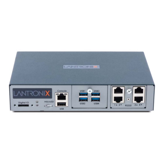
Page 26: Hardware Components
RS-232C (EIA-232) device ports. The serial RJ45 ports match the RJ45 pinouts of the console ports of many popular devices found in a network environment, and where different can be converted using Lantronix adapters. The RJ45 ports have software reversible pinouts to switch between digital terminal equipment (DTE) and digital communications equipment (DCE) applications. -
Page 27: Figure 2-4 Emg 8500 Unit (Back Side)
EMG will recognize two network connections. Either Eth1 or SFP1 is active, but not both. Similarly, either Eth2 or SFP2 is active, but not both. Lantronix offers SFP Transceivers (“modules”) for EMG 8500 edge management gateways and SLC 8000 console managers with fiber SFP ports. To learn more, go to https://www.lantronix.com/products/sfp/... -
Page 28: System Features
2: Introduction Network ports and the SFP port have LEDs to indicate link and activity status. If a single mode and a multi-mode are both installed on the EMG unit, the device can be configured to utilize one mode at a time. Power supply inlet: The unit accepts a 9 to 30 Vdc power input via a back-panel connector. -
Page 29: Device Port Interfaces
Table 2-8. The RJ45 ports have software reversible pinouts to switch between DTE and DCE applications. Note: RJ45 to DB9/DB25 adapters are available from Lantronix. For serial pinout information, see the Appendix C: Adapters and Pinouts on page 409. Additional device port features: RAW TCP, Telnet or SSH to a serial port by IP address per port or by IP address and TCP port ... -
Page 30: I/O Modules
EMG 8500 unit. Figure 2-7 shows a sample configuration of an EMG 8500 unit containing one 4 port USB I/O module in Bay 1 and one 4 port RJ45 I/O module in Bay 2 for a total of 8 device ports. -
Page 31: Network Connections
2: Introduction Network Connections Dual Ethernet Port and Dual SFP Port The back side of the EMG unit is equipped with two Ethernet and two SFP ports. The EMG network interfaces are 10/100/1000 Base-T Ethernet for use with a conventional Ethernet network as shown in Figure 2-9. -
Page 32: Connectivity Modules
2: Introduction Figure 2-10 Dual SFP Connection. Inserting the SFP transceiver Connectivity Modules EMG provides two connectivity slots for user replaceable connectivity modules on the back of the unit. Note: When installing the connectivity modules, they can be populated or swapped in any order. -
Page 33: Front Panel Leds
(terminal block) for use with sensors. The DIO port requires an adapter, which is available and sold separately. Figure 2-13 shows the DIO adapter installed on the EMG 8500 with the DIO port pin order and pin definition. EMG™ Edge Management Gateway User Guide... -
Page 34: Figure 2-13 Digital I/O Port
2: Introduction Figure 2-13 Digital I/O Port Pin Number Pin Definition Relay Out Relay In Input1+ Input1- Input2+ Input2- The DIO connector description is provided below. Connector Description Relay Output Output supports 1A 24V Inputs Inputs accept voltage 0 to 30 VDC. Max 30 VDC 2 VDC OFF: Max 0.7 VDC... -
Page 35: 3: Installation
EMG. Package Contents The EMG 8500 package includes the following items. Verify and inspect the contents of the EMG package using the enclosed packing slip. If any item is missing or damaged, contact your place of purchase immediately. -
Page 36: Order Information
For RJ45 ports, you may use a straight-through RJ45 patch cable to connect to Cisco and Sun RJ45 serial console ports. For USB ports, use a cable with a USB Type A connector For information about Lantronix adapters, see Appendix C: Adapters and Pinouts. -
Page 37: Hardware Specifications
4 port USB I/O module. May be used with a USB-to-serial adapter to connect a serial device, if needed. Please contact Lantronix for the list of tested adapters. Caution: USB ports are designed for data traffic only. They are not designed for charging or powering devices. -
Page 38: Physical Installation
3: Installation Component (continued) Description Connectivity Modules (2) connectivity slots to support 2 connectivity modules. One LTE/4G cellular modem One Wi-Fi module (coming soon) Power Input: DC jack, 9-30 VDC (standard) External AC (90W, 100-240V, 50/60 Hz) power supply shipped with unit ... -
Page 39: Rack Mount Installation
3: Installation 2. Prepare the EMG unit for installation: If free-standing, attach the adhesive-backed rubber feet to the base of the EMG unit. If rack-mounted or wall-mounted, attach the brackets on the sides of the EMG unit using a ... -
Page 40: Wall Mounting Instructions
3: Installation Figure 3-4 Rack Mount Dimensions Warning: Do not block the air vents on the sides of the EMG module. If you mount the EMG in an enclosed rack, we recommend that the rack have a ventilation fan to provide adequate airflow through the EMG unit. Wall Mounting Instructions For installations to Walls Requiring Anchors These instructions are for mounting the EMG to walls made of solid concrete, block, brick, or... -
Page 41: Connecting To A Device Port
2. Connect the other end of the Cat 5 cable to an RJ45 serial console port on the serial device or use a Lantronix serial console adapter to connect it to other port types. EMG™ Edge Management Gateway User Guide... -
Page 42: Table 3-6 Console Port And Device Port - Reverse Pinout Disabled
Table 3-6 Table 3-7 provide additional information on reverse pinouts. Appendix C: Adapters and Pinouts for information about Lantronix adapters. Table 3-6 Console Port and Device Port - Reverse Pinout Disabled Pin Number Description RTS (output) DTR (output) -
Page 43: Modular Expansion For I/O Module Bays
3: Installation Figure 3-8 Sample Device Port Connections (Front Side) Dashboard Bay 1 Bay 2 4-Port RJ45 4-Port USB I/O Module I/O Module Modular Expansion for I/O Module Bays The EMG module configuration can be changed by adding or replacing I/O modules in the I/O module bays. -
Page 44: Connecting To Network Ports
3: Installation Table 3-9 Available I/O Module Configurations Connecting to Network Ports The EMG network ports, 10/100/1000 Base-T Ethernet, allow remote access to the attached devices and the system administrative functions. Use a standard RJ45-terminated Category 5 cable to connect to the network port. A CAT5e or better cable is recommended for use with a 1000 Base-T Ethernet connection. -
Page 45: Connecting Terminals
No flow control To connect the console port to a terminal or computer with terminal emulation, Lantronix offers optional adapters that provide a connection between an RJ45 jack and a DB9 or DB25 connector. The console port is configured as DTE (non-reversed RJ45). See... -
Page 46: Power Input
3: Installation Power Input The EMG has a DC input jack connector for applying 9 to 30V DC. The EMG ships with an external 100 to 200VAC 50/60Hz to 12V DC power supply brick for supplying power to the DC input jack. -
Page 47: I/O Module Installation
3: Installation I/O Module Installation The EMG module port configuration can be changed by adding or replacing I/O modules in the I/O module bays. Warning: Install the I/O module on the front only of the EMG unit. Do not insert any other module on the front of the EMG unit. -
Page 48: Connectivity Module Installation
3: Installation into the web manager. The new module will be displayed in the Dashboard. Connectivity Module Installation The EMG module port configuration can be changed by adding or replacing connectivity modules in the connectivity module bays. Warning: Install the connectivity module on the back only of the EMG unit. Do not insert any other module on the back of the EMG unit. - Page 49 3: Installation 8. To verify the new module is recognized, connect power to the EMG, wait for it to boot, and log into the web manager. The new module will be displayed in the Dashboard. EMG™ Edge Management Gateway User Guide...
-
Page 50: 4: Quick Setup
DHCP. If you have connected Eth1 to the network, and Eth1 is able to acquire an IP address, you can view this IP address by running the Lantronix Provisioning Manager application. If Eth1 cannot acquire an IP address, you cannot use Telnet, SSH, or the web interface to run Quick Setup. -
Page 51: Lantronix Provisioning Manager
For detailed instructions, see the Lantronix Provisioning Manager online help. 1. Launch Lantronix Provisioning Manager: 2. If this is the first time you have launched Lantronix Provisioning Manager, you may need to proceed through an initial setup. 3. Locate the EMG in the device list. The device’s firmware version, serial number, IP address, and MAC address will be shown. -
Page 52: Figure 4-2 Quick Setup
4: Quick Setup Figure 4-2 Quick Setup 4. To accept the defaults, select the Accept default Quick Setup settings checkbox on the top portion of the page and click the Apply button at the bottom of the page. Otherwise, continue with step 5. -
Page 53: Network Settings
The host name becomes the prompt in the command line interface. Domain If desired, specify a domain name (for example, support.lantronix.com). The domain name is used for host name resolution within the EMG. For example, if abcd is specified for the SMTP server, and mydomain.com is specified for the domain, if abcd cannot be resolved, the EMG unit attempts to resolve abcd.mydomain.com... -
Page 54: Date & Time Settings
4: Quick Setup Date & Time Settings Date & Time Setting Description Change Date/Time Select the checkbox to manually enter the date and time at the EMG unit’s location. Date From the drop-down lists, select the current month, day, and year. Time From the drop-down lists, select the current hour and minute. -
Page 55: Method #2 Quick Setup On The Command Line Interface
3. Enter PASS as the password and press Enter. The first time you log in, the Quick Setup script runs automatically. Normally, the command prompt displays. Figure 4-5 Beginning of Quick Setup Script Welcome to the Lantronix Edge Management Gateway Model Number: EMG851000 EMG™ Edge Management Gateway User Guide... - Page 56 The host name becomes the prompt in the command line interface. Domain If desired, specify a domain name (for example, support.lantronix.com). The domain name is used for host name resolution within the EMG unit. For example, if abcd is specified for the SMTP server, and mydomain.com is specified for the domain, if abcd cannot be resolved, the EMG attempts to resolve abcd.mydomain.com for...
-
Page 57: Figure 4-6 Quick Setup Completed In Cli
After you complete the Quick Setup script, the changes take effect immediately. Figure 4-6 Quick Setup Completed in CLI Welcome to the Lantronix Edge Management Gateway Model Number: EMG851000 Quick Setup will now step you through configuring a few basic settings. -
Page 58: Next Step
4: Quick Setup Next Step After completing quick setup on the EMG, you may want to configure other settings. You can use the web page or the command line interface for configuration. For information about the web and the command line interfaces, go to Chapter 5: Web and ... -
Page 59: 5: Web And Command Line Interfaces
Web and Command Line Interfaces The EMG offers a web interface (Web Manager) and a command line interface (CLI) for configuring the EMG unit. Note: Chapter 4: Quick Setup for instructions on configuring basic network settings using the Web Manager and CLI quick setup. Web Manager A Web Manager allows the system administrator and other authorized users to configure and manage the EMG using most web browsers (Firefox, Chrome, Safari or Internet Explorer web... -
Page 60: Figure 5-2 Sample Dashboard
5: Web and Command Line Interfaces Options: Below each tab are options for specific types of settings. Note: Only those options for which the currently logged-in user has rights display. Figure 5-2 Sample Dashboard Dashboard The Dashboard buttons allow you to view and configure EMG ports and interfaces. The appearance of the dashboard will differ according to the I/O and connectivity modules installed in the EMG and the type of network interface installed. -
Page 61: Logging In
Icons: The icon bar above the Main Menu has icons that display the following: Home page. Information about the EMG unit and Lantronix contact information. Configuration site map. Status of the EMG. Help Button: Provides online Help for the specific web page. -
Page 62: Command Line Interface
5: Web and Command Line Interfaces Command Line Interface A command line interface (CLI) is available for entering all the commands you can use with the EMG. In this user guide, after each section of instructions for using the web interface, you will find a link to the equivalent CLI commands. -
Page 63: Command Line Help
5: Web and Command Line Interfaces <parameter(s)> is one or more name-value pairs in one of the following formats: User must specify one of the values ( ) separated by a <parameter name> <aa|bb> vertical line ( ). The values are in all lowercase and must be entered exactly as shown. -
Page 64: General Cli Commands
The following commands relate to the CLI itself. To configure the current command line session: set cli scscommands <enable|disable> Allows you to use Lantronix Secure Console Server (SCS)-compatible commands as shortcuts for executing commands: Note: Settings are retained between CLI sessions for local users and users listed in the remote users list. -
Page 65: Table 5-4 Cli Keyboard Shortcuts
5: Web and Command Line Interfaces Note: For information about user rights, see Chapter 13: User Authentication. Table 5-4 CLI Keyboard Shortcuts Keyboard Shortcut Description Control + [a] Move to the start of the line. Control + [e] Move to the end of the line. Control + [b] Move back to the start of the current word. -
Page 66: 6: Networking
Networking This chapter explains how to set the following network settings for the EMG using the web interface or the CLI: Network Port Settings Cellular Modem Settings IP Filter Routing VPN Settings Security Performance Monitoring ... -
Page 67: Network Port Settings
6: Networking Network Port Settings Network parameters determine how the EMG unit interacts with the attached network. Use this page to set the following basic configuration settings for the network ports (Eth1 and Eth2). The EMG supports the following types of network interfaces: RJ-45 ports, as one of the user-selectable active ports on the EMG. -
Page 68: Figure 6-1 Network > Network Settings (1 Of 2)
6: Networking To enter settings for one or both network ports: 1. Click the Network tab and select the Network Settings option. The Network > Network displays. Settings (1 of 2) Network > Network Settings (2 of 2) Figure 6-1 Network > Network Settings (1 of 2) The SFP NIC Info &... -
Page 69: Figure 6-2 Network > Network Settings (2 Of 2)
6: Networking Figure 6-2 Network > Network Settings (2 of 2) EMG™ Edge Management Gateway User Guide... -
Page 70: Ethernet Interfaces (Eth1 And Eth2)
6: Networking Figure 6-3 Network Settings > SFP NIC Information & Diagnostics 2. Enter the following information: Ethernet Interfaces (Eth1 and Eth2) Note: Configurations with the same IP subnet on multiple interfaces (Ethernet or PPP) are not currently supported. Eth 1 Settings Disabled: If selected, disables the network port. - Page 71 6: Networking IPv6 Address Address of the port in IPv6 format. (Static) Note: The EMG supports IPv6 connections for the following services: the web, SSH, Telnet, remote syslog, SNMP, NTP, LDAP, Kerberos, RADIUS, TACACS+, connections to device ports, and diagnostic ping. IPv6 addresses are written as 8 sets of 4-digit hexadecimal numbers separated by colons.
-
Page 72: Hostname & Name Servers
Domain If desired, specify a domain name (for example, support.lantronix.com). The domain name is used for host name resolution within the EMG unit. For example, if abcd is specified for the SMTP server, and mydomain.com is specified for the domain, if abcd cannot be resolved, the EMG attempts to resolve abcd.mydomain.com for... -
Page 73: Tcp Keepalive Parameters
6: Networking TCP Keepalive Parameters Start Probes Number of seconds the EMG unit waits after the last transmission before sending the first probe to determine whether a TCP session is still alive. The default is 600 seconds (10 minutes). Number of Probes Number of probes the EMG sends before closing a session. -
Page 74: Fail-Over Cellular Gateway Configuration
Select an integrated external device to be used as the fail-over gateway. Currently the Lantronix PremierWave XC HSPA+ Cellular Gateway and the Sierra Wireless AirLink ES450 are supported. When using an internal cellular modem as the fail- over gateway, the Fail-over Device should be set to None. -
Page 75: Advanced Cellular Gateway Configuration
6: Networking New Admin For the selected Fail-over Device, the administrator password can be changed on Password/Retype the gateway. The password may have up to 64 characters. To change the Admin Password, click the Change Admin Password checkbox and enter the new password in the New Admin Password and Retype fields. Changing the HSPA+ Admin password will save the password on the EMG for status and configuration queries to the HSPA+ gateway. -
Page 76: Load Cellular Gateway Firmware Options
6: Networking Radio Firmware Enter the name of the radio firmware filename exactly as it is represented. Filename Load Firmware via Select the method to load the firmware from the options in the drop-down menu. Options are: FTP, SFTP, SCP, USB, SD Card, and HTTPS. FTP is the default. If you select HTTPS, the Upload File link becomes active. -
Page 77: Cellular Modem Settings
6: Networking Cellular Modem Settings The EMG supports the use of one internal LTE cellular modem installed in the EMG unit. The Cellular Settings web page allows the user to configure parameters that determine how the EMG cellular modem network behaves, and to update the cellular modem firmware. To complete the Cellular Settings page: 1. -
Page 78: Cellular Interface
6: Networking 2. Enter the following information: Cellular Interface Cell Settings Disabled: If selected, disables the cellular interface. Default is enabled for DHCP. Obtain from DHCP: Acquires IP address and subnet mask from DHCP. IP Address (view only) An IP address acquired via DHCP. Subnet Mask (view only) The network segment acquired via DHCP. -
Page 79: Ip Filter
6: Networking IP Filter IP filters (also called a rule set) act as a firewall to allow or deny an individual MAC address or individual or a range of IP addresses, ports, and protocols. When a network connection is configured to use an IP filter, all network traffic through that connection is compared, in order, to the rules of that filter. -
Page 80: Enabling Ip Filters
6: Networking 3. From the Interface drop-down list, select the desired network interface and click the Map Ruleset button. The Interface and rule set display in the IP Filter Mappings table. To delete a mapping: 1. Click the Network tab and select the IP Filter option. The Network >... -
Page 81: Configuring Ip Filters
6: Networking Configuring IP Filters The administrator can add, edit, delete, and map IP filters. Note: A configured filter has no effect until it is mapped to a network interface. See Mapping Rulesets on page 79. To add an IP filter: 1. -
Page 82: Rule Parameters
6: Networking Rule Parameters IP Address(es) Specify a single IP address to act as a filter. Example: 172.19.220.64 – this specific IP address only Subnet Mask Specify a subnet mask to determine how much of the address should apply to the filter. -
Page 83: Deleting An Ip Filter
6: Networking 1. From the Network > IP Filter page, the administrator selects the IP filter rule set to be edited and clicks the Edit Ruleset button to return to the Network > IP Filter Ruleset (Adding/Editing Rulesets) page (see Figure 6-6). -
Page 84: Dynamic Routing
6: Networking Dynamic Routing Enable RIP Select to enable Dynamic Routing Information Protocol (RIP) to assign routes automatically. Disabled by default. RIP Version Select the RIP version. The default is 2. Static Routing Enable Static Select to assign the routes manually. The system administrator usually provides the Routing routes. - Page 85 6: Networking (IKEv1 Aggressive and 3DES_CBC/HMAC_MD5_96/PRF_HMAC_MD5/MODP_1024), when the tunnel will be rekeyed/SA Lifetime (rekeying in 7 hours), the bytes in and out (131 bytes_i (1 pkt, 93s ago), 72 bytes_o (1 pkt, 94s ago)), a dynamic address assigned to the console manager side of the tunnel (child: dynamic and 172.28.28.188), and the subnets on both sides of the tunnel (172.28.28.188/32 === 10.3.0.0/24 10.81.101.0/24 10.81.102.0/24 10.81.103.0/24).
-
Page 86: Figure 6-8 Network > Vpn (1 Of 2)
6: Networking (console manager) side of the tunnel based on the network configuration during both fail-over and fail-back. VPN tunnels over an console manager Ethernet interfaces that is configured with an MTU less than 256 may experience issues (traffic loss, etc). To set up a VPN connection: 1. -
Page 87: Figure 6-9 Network > Vpn (2 Of 2)
6: Networking Figure 6-9 Network > VPN (2 of 2) 2. Enter the following: Enable VPN Tunnel Select to create a tunnel. Disabling this option will terminate any currently running tunnel. Note: The VPN peer that sends the first packet in tunnel bringup is the initiator or client;... - Page 88 6: Networking Remote Subnet(s) One or more allowed subnets behind the remote host, expressed in CIDR notation (IP address/mask bits). If multiple subnets are specified, the subnets should be separated by a comma. Up to 10 local subnets supported. Configured subnets of the peers may differ, the protocol narrows it to the greatest common subnet.
- Page 89 6: Networking IKE Negotiation The Internet Key Exchange (IKE) protocol is used to exchange security options between two hosts who want to communicate via IPSec. The first phase of the protocol authenticates the two hosts to each other and establishes the Internet Security Association Key Management Protocol Security Association (ISAKMP SA).
- Page 90 6: Networking ESP Encryption The type of encryption, 3DES , AES, AES192 or AES256, used for encrypting the data sent through the tunnel. Any can be selected if the two sides can negotiate which type of encryption to use. Note: If ESP Encryption, Authentication and DH Group are set to Any, default cipher suite(s) will be used.
- Page 91 6: Networking Authentication The type of authentication used by the host on each side of the VPN tunnel to verify the identity of the other host. For RSA Public Key, each host generates a RSA public-private key pair, and shares its public key with the remote host. The RSA Public Key for the EMG (which has 4096 bits) can be viewed at either the web or CLI.
- Page 92 6: Networking Certificate Authority for A certificate can be uploaded to the EMG unit for peer authentication. The Local Peer certificate for the local peer is used to authenticate any remote peer to the EMG, and contains a Certificate Authority file, a public certificate file, and a Certificate File for Local private key file.
- Page 93 6: Networking Mode Config In remote access scenarios, it is highly desirable to be able to push configuration information such as the private IP address, a DNS server's IP address, and so forth, to the client. This option defines which mode is used: pull where the config is pulled from the peer (the default), or push where the config is pushed to the peer.
- Page 94 6: Networking Custom ipsec.conf A custom ipsec.conf file can be uploaded to the EMG. This file can include Configuration any of the strongSwan options which are not configurable from the UIs. The ipsec.conf file should include one section which conn <Tunnel Name> defines the tunnel parameters.
-
Page 95: Sample Ipsec.conf Files
6: Networking Sample ipsec.conf Files Sample ipsec.conf files are provided for a variety of tunnel setups and peers. In all examples, any left options are for the console manager/local side of the tunnel, and any right options are for the remote side of the tunnel. - Page 96 6: Networking Cisco ASA5525x Pre-Shared Key / IKEv1 This configuration is an example of a remote access connection to a Cisco ASA5525 VPN server / responder. EMG configuration The pre-shared key needs to be configured via the console manager UI. conn ASA5525 keyexchange=ikev1 ike=aes-sha1-modp1536!
- Page 97 6: Networking crypto ipsec security-association pmtu-aging infinite crypto map site2site 10 match address asa-router-vpn set pfs group5 set peer 192.168.1.204 set ikev1 transform-set ipsecvpn crypto map site2site interface outside crypto ikev1 enable outside crypto ikev1 policy 10 authentication pre-share encryption aes hash sha group 5 lifetime 86400...
- Page 98 6: Networking Cisco configuration interface GigabitEthernet0/0 nameif outside security-level 0 ip address 192.168.1.130 255.255.255.0 interface GigabitEthernet0/3 nameif inside security-level 100 ip address 192.168.3.130 255.255.255.0 object-group network local-network network-object 192.168.3.0 255.255.255.0 network-object 192.168.3.250 255.255.255.255 object-group network remote-network network-object 192.168.0.0 255.255.255.0 network-object 192.168.0.222 255.255.255.255 access-list asa-router-vpn extended permit ip object-group local-network object-group remote-network access-list ASA-SLC-ACCESS extended permit ip object-group local-network...
- Page 99 6: Networking Cisco ISR 2921 Pre-Shared Key / XAUTH / IKEv2 This configuration is an example of a remote access connection to a Cisco ISR2921 VPN server / responder. Console manager configuration The pre-shared key needs to be configured via the console manager UI. conn ISR2921 keyexchange=ikev2 ike=aes-sha2_384-modp1536!
-
Page 100: Vpn Commands
6: Networking group 2 crypto isakmp policy 5 encr 3des authentication pre-share group 5 crypto isakmp policy 10 lifetime 120 crypto isakmp key cisco123 address 192.168.1.100 crypto ipsec transform-set ISR esp-3des esp-sha384-hmac mode tunnel crypto map CM 10 ipsec-isakmp set peer 192.168.1.100 set transform-set ISR set ikev2-profile IKEv2_Profile match address VPN-TRAFFIC... -
Page 101: Security
6: Networking Security Note: FIPS 140-2 standard is not supported in the current release. The EMG supports a security mode that complies with the FIPS 140-2 standard. FIPS (Federal Information Processing Standard) 140-2 is a security standard developed by the United States federal government that defines rules, regulations and standards for the use of encryption and cryptographic services. -
Page 102: Figure 6-10 Network > Security
6: Networking LDAP authentication must be configured with the following: StartTLS encryption (SSL encryption over port 636 is not supported) A SSL/secure certificate Either Bind with Login or a Bind Name and Password Note: In FIPS mode, passphrases are not supported for SSH keys and SSL certificates. Figure 6-10 Network >... -
Page 103: Performance Monitoring
6: Networking Performance Monitoring The EMG supports Performance Monitoring probes for analyzing network performance. Probes for DNS Lookup, HTTP Get, ICMP Echo, TCP Connect, UDP Jitter and UDP Jitter VoIP are supported. Up to 15 different probes can be configured. Each probe will run a series of operations, each of which sends a series of packets to a destination host. -
Page 104: Figure 6-11 Network > Perf Monitoring
6: Networking To manage or view status for a Performance Monitoring probe: 1. Click the Network tab and select the Perf Monitoring option. The following page displays. Figure 6-11 Network > Perf Monitoring 2. In the upper section of the page, modify the global Performance Monitoring settings: Number of operations Specifies the number of operation set files to keep for each probe. - Page 105 6: Networking UDP Echo Responder Starts the UDP Echo responder on the port configured in UDP Port to reply to UDP echo packets. The EMG UDP Echo responder supports one UDP echo sender. When the UDP Echo responder is enabled, the EMG will verify that the responder UDP port is not being used by any other EMG processes, including port 1967 which is reserved for the UDP Jitter responder.
-
Page 106: Performance Monitoring - Add/Edit Probe
6: Networking Performance Monitoring - Add/Edit Probe Performance Monitoring - Add/Edit Probe web page allows a user to add a new Performance Monitoring probe or edit an existing Performance Monitoring probe. To add a new probe or edit an existing probe: 1. - Page 107 6: Networking 3. Modify the probe settings: Probe Type Select from one of the available probe types: DNS Lookup - Performs a DNS lookup on the hostname specified in the Destination Host using the Name Server. By default port 53 is always used as the Destination Port.
- Page 108 6: Networking Data Size The size in bytes to use for the payload portion of the packet - this size is in addition to the IPv4 header and the TCP, UDP or ICMP header. Any additional space in the packet that is not used by the protocol will be padded with random data that can be used for data verification (see below).
-
Page 109: Performance Monitoring - Results
6: Networking Performance Monitoring - Results The Performance Monitoring - Operations page displays all of the operations that have been saved for a selected probe. The probe ID and name are shown at the top of the web page. From this page, the user may select any operation to view its round trip time (RTT) results, or the accumulated statistics for all round trip times in an operation. - Page 110 6: Networking Accumulated Statistics A summary of all round trip time and any error conditions is displayed. The display will vary for non-jitter and jitter results. For example, non-jitter accumulated results will show: Latest Accumulated Statistics Probe 1/ICMP, operation icmp_190709_154501.dat: Operation Type: ICMP Echo to 172.19.100.17, Ethernet Port: both 10 packets sent 500 ms apart, timeout 200 ms...
-
Page 111: Table 6-13 Error Conditions Detected By Probes
6: Networking Positive Min/Avg/Max: 0/0/0 msec Positive Number Of/Sum of All/Sum of All Squared: 0/0/0 msec Negative Min/Avg/Max: 0/0/0 msec Negative Number Of/Sum of All/Sum of All Squared: 0/0/0 msec Number of Successes: 10 Number of Errors: 0 Lost Packet: 0 (0%) Out of Sequence: 0 Late Arrival: 0 Miscellaneous Error: 0... -
Page 112: Performance Monitoring Commands
6: Networking To view results for a Performance Monitoring probe: 1. Click the Network tab and select the Perf Monitoring option. The Network > Perf Monitoring page displays. 2. Select a probe from the table in the lower part of the page and select the Operations link. The Performance Monitoring - Operations page displays. -
Page 113: Fqdn List
6: Networking FQDN List Use the FQDN List (FQDN stands for fully qualified domain name) to add static hostname entries to the local hosts table so that the EMG can resolve hostnames that are not resolved via DNS. To add/edit/delete hosts: 1. -
Page 114: 7: Services
Identify a Simple Mail Transfer Protocol (SMTP) server. Configure an audit log. View the status of and manage the EMGs on the Secure Lantronix network. Set the date and time. Configure NFS and CIFS shares. -
Page 115: System Logging
7: Services Figure 7-1 Services > SSH/Telnet/Logging 2. Enter the following settings: System Logging Alert Levels Select one of the following alert levels from the drop-down list for each message category: Off: Disables this type of logging. Error: Saves messages that are output because of an error. ... -
Page 116: Audit Log
7: Services Diagnostics Messages concerning system status and problems. General Any message not in the categories above. Remote Servers The IPv4 or IPv6 address of the remote server(s) where system logs are stored. (#1 and #2) The system log is always saved to local EMG storage. It is retained through EMG unit reboots for files up to Other Log Size (see below). -
Page 117: Telnet
7: Services Timeout Data If idle connection timeouts are enabled, this setting indicates the direction of data used Direction to determine if the connection has timed out. Select the type of data direction: Both Directions Incoming Network Outgoing Network ... -
Page 118: Ssh Commands
EMG unit. It provides read-write access to a select set of functions for controlling the EMG unit and device ports. See the MIB definition file for details. The EMG MIB definition file and the top level MIB file for all Lantronix products are accessible from the SNMP web page. To configure SNMP: 1. -
Page 119: Figure 7-2 Services > Snmp
7: Services Figure 7-2 Services > SNMP 2. Enter the following: Enable Agent Enables or disables the Simple Network Management Protocol (SNMP) agent, which allows read-only access to the system. Disabled by default. EMG™ Edge Management Gateway User Guide... - Page 120 7: Services Top Level MIB Click the link to access the top level MIB file for all Lantronix products. (link) EMG MIB (link) Click the link to access the EMG MIB definition file for EMGs. EMG MON MIB Click the link to access the EMG monitor MIB definition file for EMGs.
-
Page 121: V1/V2C Communities
7: Services NMS #1 (or #2) When SNMP is enabled, an NMS (Network Management System) acts as a central server, requesting and receiving SNMP-type information from any computer using SNMP. The NMS can request information from the EMG and receive traps from the EMG unit. -
Page 122: V3 User Read-Write
7: Services V3 User Read-Write User Name SNMP v3 is secure and requires user-based authorization to access objects. Enter a user ID for users with read-write authority. The default is snmprwuser. Up to 20 characters. Password/ Password for the user with read-write authority to use to access SNMP v3. The default Retype Password is SNMPRWPASS. -
Page 123: Figure 7-3 Services > Nfs & Smb/Cifs
7: Services To configure NFS and SMB/CIFS: 1. Click the Services tab and select the NFS/CIFS option. The following page displays: Figure 7-3 Services > NFS & SMB/CIFS 2. Enter the following for up to three directories: NFS Mounts Remote Directory The remote NFS share directory in the format: nfs_server_hostname or ipaddr:/exported/path Local Directory... -
Page 124: Smb/Cifs Share
7: Services 3. Enter the following: SMB/CIFS Share Share SMB/CIFS Select the checkbox to enable the EMG to export an SMB/CIFS share called “public.” directory Disabled by default. Network Select the network ports from which the share can be seen. The default is for the share Interfaces to be visible on both network ports. -
Page 125: Secure Lantronix Network
To directly access the web interface for a secure Lantronix device: 3. On the Secure Lantronix Network page, click the IP address of a specific secure Lantronix device to open a new browser page with the web interface for the selected device. -
Page 126: Figure 7-5 Ip Address Login Page
1. Make sure that Web Telnet or Web SSH is enabled for the specific device. 2. On the Secure Lantronix Network page, click the SSH or Telnet link in the SSH/Telnet to CLI column directly beside the device you would like to access. -
Page 127: Browser Issues
Secure Lantronix Page Click the Services tab, then click the Secure Lantronix Network link (see Figure 7-4.) Select the port you want to configure. Enabled port numbers are in bright green boxes and will allow you to select either a WebSSH or a WebTelnet session. -
Page 128: Troubleshooting Browser Issues
5. To delete an IP address from the IP Address List, select the address and click the Delete IP Address button. 6. Click the Apply button. When the confirmation message displays, click Secure Lantronix Network on the main menu. The Services >... - Page 129 "EMGXYZ.lantronix.com", and the unit website is being accessed in a browser with "https:// EMGXYZ.lantronix.com", the unit needs to be configured with a name server that will allow the unit to perform a reverse lookup on the IP address associated with EMGXYZ.lantronix.com. Failure to perform a reverse lookup on a name may result in name mismatch errors in the browser when it attempts to open the Web SSH or Web Telnet window.
-
Page 130: Web Ssh/Telnet Copy And Paste
Enter, the content will be sent to the Web SSH or Web Telnet window. Secure Lantronix Network Commands Go to SLC Network Commands (on page 390) to view CLI commands which correspond to the web page entries described above. -
Page 131: Date And Time
7: Services Date and Time Use the Date and Time Settings page to specify the local date, time, and time zone at the EMG location, or enable the EMG unit to use NTP to synchronize with other NTP devices on your network. -
Page 132: Date And Time Commands
7: Services 2. Enter the following: Change Date/Time Select the checkbox to manually enter the date and time at the location. Date From the drop-down lists, select the current month, day, and year. Time From the drop-down lists, select the current hour and minute. Time Zone From the drop-down list, select the appropriate time zone. -
Page 133: Web Server
7: Services Web Server The Web Server supports all versions of the TLS protocol, but due to security concerns, does not support any versions of the SSL protocol. The Web Server page allows the system administrator Configure attributes of the web server. ... - Page 134 7: Services 2. Enter the following fields: Timeout Select No to disable Timeout. Select Yes, minutes (5-120) to enable timeout. Enter the number of minutes (must be between 30 and 120 minutes) after which the EMG web session times out. The default is 30. Note: If a session times out, refresh the browser page and login to a new web session.
-
Page 135: Admin Web Commands
7: Services 3. Click the Apply button to save. Admin Web Commands Go to to view CLI commands which correspond to the web page entries Administrative Commands described above. Services - SSL Certificate Services > Web Server page enables you to view and update SSL certificate information. The SSL certificate, consisting of a public/private key pair used to encrypt HTTP data, is associated with the web server. -
Page 136: Figure 7-11 Web Server - Ssl Certificate
7: Services Figure 7-11 Web Server - SSL Certificate 2. If desired, enter the following: Reset to Default To reset to the default certificate, select the checkbox to reset to the default Certificate certificate. Unselected by default. Root Filename Filename of the imported root or intermediate Certificate Authority. If HTTPS is selected as the method for import, the Upload File link will be selectable to upload a Certificate authority. - Page 137 The locality or city for the custom certificate, e.g. "Irvine". Must be at least 2 characters long. Organization Name The organization or company name for the custom certificate, e.g. "Lantronix". Must be at least 2 characters long. Organization Unit The unit name for the custom certificate, e.g. "Engineering" or "Sales". Must be at Name least 2 characters long.
-
Page 138: Services - Web Sessions
Services > Web Server ConsoleFlow ConsoleFlow is a cloud or on-premise portal for the centralized management of multiple Lantronix ITM devices. A browser based interface (including mobile phone app support) allows an administrator to view status, send commands, view logs and charts and update firmware. Each Lantronix device can communicate with the cloud server or on-premise server, sending status updates and responding to commands sent by the server. - Page 139 7: Services Device ID is invalid, the Registration Host name cannot be resolved, or the Registration Host is not reachable. Once registration is successful, Status of Client will display Registered with the date and time of registration. Note that the Registered date/time displayed in the EMG status may be different from the registered date/time shown in the ConsoleFlow web UI.
-
Page 140: Figure 7-13 Services > Consoleflow
7: Services To configure ConsoleFlow settings: 1. Click the Services tab and select the ConsoleFlow option. The following page displays. Figure 7-13 Services > ConsoleFlow EMG™ Edge Management Gateway User Guide... - Page 141 Long description that is displayed in the ConsoleFlow server UI. Device ID The unique device identifier. The ID is 32 alphanumeric characters. The ID may be provisioned using Lantronix Provisioning Manager (LPM). Contact Lantronix Tech Support for more information on LPM. Displays the serial number.
-
Page 142: Consoleflow Commands
7: Services ConsoleFlow Cloud Settings and ConsoleFlow On-Premise Settings Registration Host Hostname of the server the client registers with. The Host Name should start with api. Registration Port The TCP port on the Registration Host. Defaults to 443. Use HTTPS for If enabled, HTTPS (instead of HTTP) is used for registration. -
Page 143: 8: Usb/Sd Card Port
USB/SD Card Port This chapter describes how to configure storage by using the Devices > USB / SD Card page and CLI. This page can be used to configure the micro SD card or the USB flash drive (thumb drive). The USB flash drive or micro SD card is useful for firmware updates, saving and restoring configurations and for device port logging. -
Page 144: Figure 8-1 Devices > Usb / Sd Card
8: USB/SD Card Port Figure 8-1 Devices > USB / SD Card To configure a USB/SD card storage port: 1. Insert any of the supported storage devices into the USB port or the SD card slot on the front of the EMG unit. 2. -
Page 145: Figure 8-2 Devices > Usb > Configure
8: USB/SD Card Port Figure 8-2 Devices > USB > Configure Figure 8-3 Devices > SD Card > Configure 5. Enter the following fields. Mount Select the checkbox to mount the first partition of the storage device on the EMG unit (if not currently mounted). Once mounted, a USB thumb drive or SD card is used for firmware updates, device port logging and saving/restoring configurations. -
Page 146: Manage Files
8: USB/SD Card Port Unmount To eject the USB thumb drive or SD card from the EMG unit , first unmount the thumb drive or SD card . Select the checkbox to unmount it. Warning: If you eject a thumb drive or SD card from the EMG unit without unmounting it, subsequent mounts of a USB thumb drive or SD card in may fail, and you will need to reboot the device to restore thumb drive or SD card functionality. -
Page 147: Usb Commands
8: USB/SD Card Port Figure 8-4 Firmware and Configurations - Manage Files Note: The Delete, Download, and Rename options are at the bottom of the page (Figure 8-4). 2. To delete a file, click the check box next to the filename and click Delete File. A confirmation message displays. -
Page 148: 9: Device Ports
Device Ports This chapter describes how to configure and use an EMG port connected to an external device, such as a server or a modem. This chapter also describes how to configure the console port. describes how to use the web page to connect Chapter 12: Connections Devices >... -
Page 149: I/O Modules
9: Device Ports 3. Clear mode: The user can clear the contents of the device port buffer (set locallog <port> clear buffer command). The administrator and users with local user rights may assign individual port permissions to local users. The administrator and users with remote authentication rights assign port access to users authenticated by NIS, RADIUS, LDAP, Kerberos and TACACS+. -
Page 150: Device Status
9: Device Ports Device Status page displays the status of the EMG ports, the USB port and SD Devices > Device Status card port. Click the Devices tab and select the Device Status option. The following page displays: Figure 9-2 Devices > Device Status Device Ports On the Devices >... -
Page 151: Figure 9-3 Devices > Device Ports
9: Device Ports Figure 9-3 Devices > Device Ports Current port numbering schemes for Telnet, SSH, and TCP ports display on the left. The list of ports on the right includes the individual ports and their current mode. Note: Icons that represent some of the possible modes include: Idle The port is not in use. -
Page 152: Telnet/Ssh/Tcp In Port Numbers
9: Device Ports Telnet/SSH/TCP in Port Numbers Starting Telnet Port Each port is assigned a number for connecting via Telnet. Enter a number (1025- 65528) that represents the first port. The default is 2000 plus the port number. For example, if you enter 2001, port 1 will be 2001 and subsequent 2000 ports are automatically assigned numbers 2001, 2002, and so on. - Page 153 9: Device Ports Dashboard Make sure the Configuration radio button directly beneath the is selected and Dashboard click the desired port number in the Dashboard. The Dashboard is located on the upper right corner of each Web Manager page (see Chapter 5: Web Manager.) Device Ports Page...
-
Page 154: Figure 9-4 Device Ports > Settings (1 Of 2)
9: Device Ports The following page displays: Figure 9-4 Device Ports > Settings (1 of 2) EMG™ Edge Management Gateway User Guide... -
Page 155: Device Port Settings
9: Device Ports Figure 9-5 Device Ports > Settings (2 of 2) 2. Enter the following: Device Port Settings Port Displays number of port; displays automatically. Mode The status of the port; displays automatically. USB Device This field is only displayed for USB ports. If a USB device is connected to the device port, this displays the USB version, speed, and a short type description for the USB device. - Page 156 9: Device Ports Detect Port Name If enabled, the EMG will attempt to detect the hostname of the device connected to the device port, and set the device port name to the detected hostname. Many devices use their hostname or another identifier as the device prompt, and the EMG can extract this name from the prompt using the Detect Name Tokens.
-
Page 157: Ip Settings
9: Device Ports Break Sequence A series of one to ten characters users can enter on the command line interface to send a break signal to the external device. A suggested value is Esc+B (escape key, then uppercase “B” performed quickly but not simultaneously). You would specify this value as \x1bB, which is hexadecimal (\x) character 27 (1B) followed by a B. -
Page 158: Data Settings
9: Device Ports Seconds Enter a value from 1 to 3600 seconds if selecting the Telnet, SSH or TCP Timeout checkbox to the left. The default is 600 seconds. Note: When the Idle Timeout Msg is enabled, the terminal application timeout values for Telnet, SSH and TCP should be set to a value greater than 15 seconds. -
Page 159: Hardware Signal Triggers
9: Device Ports Parity Parity checking is a rudimentary method of detecting simple, single-bit errors. From the drop-down list, select the parity. The default is none. Flow Control A method of preventing buffer overflow and loss of data. The available methods include none, xon/xoff (software), and rts/cts (hardware). -
Page 160: Modem Settings (Device Ports)
Ethernet patch cable, without the need for a rolled cable or adapter. Enabled by default. Note: Applies to serial RJ45 device ports only. All Lantronix serial adapters are intended to be used with Reverse Pinout disabled. USB VBUS For USB Device Ports only. -
Page 161: Modem Settings: Text Mode
9: Device Ports Use Sites Enables the use of site-oriented modem parameters which can be activated by various modem-related events (authentication, outbound network traffic for dial- on-demand connections, etc.). Sites can be used with the following modem states: dial-in, dial-back, dial-on-demand, dial-in & dial-on-demand, dial-back & dial-on-demand, and CBCP server. -
Page 162: Modem Settings: Ppp Mode
9: Device Ports Modem Settings: PPP Mode Negotiate IP Address If the EMG unit and/or the serial device have dynamic IP addresses (e.g., IP addresses assigned by a DHCP server), select Yes. Yes is the default. If the EMG or the modem have fixed IP addresses, select No, and enter the Local IP (IP address of the port) and Remote IP (IP address of the modem). -
Page 163: Port Status And Counters
9: Device Ports From the Apply Settings drop-down box, select none, a group of settings, or All. In to Device Ports, type the device port numbers, separated by commas; indicate a range of port numbers with a hyphen (e.g., 2, 5, 7-10). Note: It may take a few minutes for the system to apply the settings to multiple ports. - Page 164 9: Device Ports This menu allows the administrator to query status and control any of the power supplies that provide power to the device connected to the device port and change the Baud Rate of the device port. Note: The Baud Rate can be configured while connected to a device port by entering the Power Management Sequence.
-
Page 165: Figure 9-7 Device Ports - Power Management
9: Device Ports Figure 9-7 Device Ports - Power Management 3. Enter the following: Power Management A series of one to ten characters that will display the Power Management menu Sequence when connected to the device port. The default value is Esc+P (escape key, then uppercase "P"). -
Page 166: Device Port - Sensorsoft Device
9: Device Ports Outlet For each managed power supply, enter the outlet on the selected RPM. As an aid to selecting the outlet, click the View Outlets button, then select an outlet from the list and click the Select Outlet button. The managed power supply outlet number will be filled in, as well as the managed power supply outlet name if a name is listed for the outlet and one has not already been defined for the managed power supply. -
Page 167: Figure 9-8 Devices > Device Ports - Sensorsoft
9: Device Ports Figure 9-8 Devices > Device Ports - Sensorsoft 4. Select a port and enter or view the following information: Dev Port Displays the number of the EMG port. Device Port Name Displays the name of the EMG port. Curr Temp Current temperature (degrees Celsius) on the device the sensor is monitoring. -
Page 168: Device Port Commands
9: Device Ports Figure 9-9 Sensorsoft Status Device Port Commands Go to Device Port Commands to view CLI commands which correspond to the web page entries described above. Device Commands Go to Device Commands to view CLI commands which correspond to the web page entries described above. -
Page 169: Device Ports - Logging And Events
9: Device Ports user <Login Name> version <1|2> command <Command to Execute> tcp <IP Address> port <TCP Port> telnet <IP Address> [port <TCP Port>] udp <IP Address> port <UDP Port> hostlist <Host List> Notes: To escape from the connect direct command when the endpoint of the command is deviceport, tcp, or udp and return to the command line interface, type the escape sequence assigned to the currently logged in user. -
Page 170: Usb And Sd Card Logging
9: Device Ports 02_Port-2_2.log 02_Port-2_3.log 02_Port-2_4.log 02_Port-2_5.log USB and SD Card Logging Data can be logged to a USB flash drive or the SD card slot on the front of the EMG unit and properly mounted. Data logged locally to the EMG is limited to 256 Kbytes and may be lost in the event of a power loss. -
Page 171: Token & Data Detection
9: Device Ports Figure 9-10 Devices > Device Ports - Logging & Events 2. Enter the following: Token & Data Detection Token & Data Select to enable token and data detection on the selected device port, with a set of Detection actions that can be enabled if a data trigger occurs. - Page 172 9: Device Ports Byte Threshold The number of bytes of data the port will receive before the EMG unit will capture log data and initiate the selected actions. The default is 100 bytes. In most cases, the console port of your device does not send any data unless there is an alarm condition.
-
Page 173: Local Logging
9: Device Ports Local Logging Local Logging If you enable local logging, each device port stores 256 Kbytes (approximately 400 screens) of I/O data in a true FIFO buffer. Disabled by default. Clear Local Log Select the checkbox to clear the local log. View Local Log Click this link to see the local log in text format. -
Page 174: Logging Commands
9: Device Ports range of port numbers with a hyphen (e.g., 2, 5, 7-10), and separate ranges with commas. 4. To save, click the Apply button. Logging Commands Go to to view CLI commands which correspond to the web page entries Logging Commands described above. -
Page 175: Console Port Commands
9: Device Ports Parity Parity checking is a rudimentary method of detecting simple, single-bit errors. From the drop-down list, select the parity. The default is none. Flow Control A method of preventing buffer overflow and loss of data. The available methods include none, xon/xoff (software), and rts/cts (hardware). -
Page 176: Dio Commands
9: Device Ports To configure the DIO ports: 1. Change the following Front #1 and Front #2 Input port fields: Name The name of the port. Valid characters are letters, numbers, dashes (-), periods and underscores (_). State (view only) Displays the current state of the port: on or off. Normal State Defines the typical or normal state of the DIO Input port. - Page 177 9: Device Ports received. In order to use one of the protocols, the device port that will be used must not be currently in use for any other purpose. An example of sending a file with Zmodem to device port 3 using the CLI: [emg431d]>...
- Page 178 9: Device Ports 1. Click the Devices tab and select the Xmodem option. The Xmodem page displays: 2. To upload a file to the repository, click the Upload File link and upload a file in the window that is displayed. Upload file size should not exceed 20 MB. The maximum length for the upload file name is 40 characters.
-
Page 179: Xmodem Commands
9: Device Ports can be opened to view the progress of the send. When the Xmodem protocol is used, the user will be prompted when to start the file receive with the message, “Give your local XMODEM receive command now.” Note: Ymodem transfers may display a line at the end of a successful transfer such as, “Ymodem sectors/kbytes sent: 0/ 0k”, however, the transfer is successful if... -
Page 180: Host Lists
9: Device Ports Host Lists A host list is a prioritized list of SSH, Telnet, and TCP hosts available for establishing incoming modem connections or for the connect direct command on the CLI. The EMG unit cycles through the list until it successfully connects to one. To add a host list: 1. - Page 181 9: Device Ports Protocol Protocol for connecting to the host (TCP, SSH, or Telnet). Port Port on the host to connect to. Escape Sequence The escape character used to get the attention of the SSH or Telnet client. It is optional, and if not specified, Telnet and SSH use their default escape character.
-
Page 182: Figure 9-13 Devices >View Host Lists
9: Device Ports To view or update a host list: 1. In the Host Lists table, select the host list and click the View Host List button. The list of hosts display in the Hosts box. Figure 9-13 Devices >View Host Lists 2. -
Page 183: Host List Commands
9: Device Ports Escape Sequence The escape character used to get the attention of the SSH or Telnet client. It is optional, and if not specified, Telnet and SSH use their default escape character. For Telnet, the escape character is either a single character or a two-character sequence consisting of '^' followed by one character. -
Page 184: Figure 9-14 Devices > Sites
9: Device Ports To add a site: 1. Click the Devices tab and select the Sites option. The Sites page displays: Figure 9-14 Devices > Sites 2. In the lower section of the page, enter the following: Note: To clear fields in the lower part of the page, click the Reset Site button. Site Id Displays after a site is created. - Page 185 9: Device Ports Login/CHAP Host The login name (for PAP authentication) or CHAP host (for CHAP authentication) associated with this site. If a modem has sites enabled and the authentication is successful at dial-in (for modem states dial-in, dial-back, CBCP server, dial-in & dial-on-demand, or dial-back &...
-
Page 186: Site Commands
9: Device Ports Modem Timeout Timeout for dial-in and dial-on-demand PPP connections. Select Yes (default) for the EMG to terminate the connection if no traffic is received during the configured idle time. Enter a value of from 1 to 9999 seconds. The default is 30 seconds. Restart Delay The number of seconds after the modem timeout and before the EMG unit attempts another connection. -
Page 187: Dial-Back
9: Device Ports connected to the EMG until they either logout of the CLI session, or (if Timeout Logins is enabled) the CLI session is terminated if it has been idle. For PPP connections, the user will be authenticated via PAP or CHAP (determined by the ... -
Page 188: Dial-On-Demand
9: Device Ports enabled for the site and a Dial-back Number is defined, the EMG unit will hang up and wait Dial-back Delay seconds before initiating the dial-back. The EMG will dial, and if the remote peer requests PAP or CHAP authentication, provide the Dial-out Login and Dial-out Password as authentication tokens. -
Page 189: Dial-Back & Dial-On-Demand
9: Device Ports will be established using either negotiated IP addresses or specific IP addresses (determined by the Negotiate IP Address setting). The PPP connection will stay active until no IP traffic is sent for Modem Timeout seconds. Once the timeout has expired, the PPP connection will be terminated and will not be reestablished for at least Restart Delay seconds. -
Page 190: Cbcp Server
9: Device Ports server use an administrator-defined number to dial on callback. Optionally, some servers may also allow "no callback" as an option. CBCP Server The EMG waits for a client to call the EMG unit, establishes a PPP connection, authenticates the user, and negotiates a dial-back number with the client using CBCP. -
Page 191: Key Sequences
9: Device Ports Key Sequences The default values for the various key sequences (Escape Sequence, Break Sequence, View Port Log Sequence, Power Menu Sequence) are set to different key sequences, and it is recommended that they always be set to different key sequences so that the EMG can properly handle each of the functions accessed by the key sequence while connected to a device. -
Page 192: 10: Remote Power Managers
10: Remote Power Managers The EMG supports managing remote power managers (RPMs) for devices from over 140 vendors. The RPM can be either a power distribution unit (PDU) or uninterruptible power source/supply (UPS), and can be managed via SNMP, serial port, network and USB connections. The RPMs web page displays a list of all currently managed RPMs with an overview of their current status, with options to control and view detailed status for each RPM, depending on its supported capabilities. -
Page 193: Figure 10-2 Rpm Shutdown Order
10: Remote Power Managers Notifications Displays the notifications configured for each PDU and UPS. See Figure 10-3. Raw Data Displays a window with all of the information returned by the driver when a query for status is requested. This option is available for all RPMs. -
Page 194: Figure 10-3 Rpm Notifications
10: Remote Power Managers Figure 10-3 RPM Notifications Figure 10-4 RPM Raw Data Log EMG™ Edge Management Gateway User Guide... -
Page 195: Rpms - Add Device
10: Remote Power Managers Figure 10-5 RPM Logs Figure 10-6 RPM Environmental Log RPMs - Add Device The Add Device page assists the administrator with adding a new managed RPM to the EMG configuration. With over 140 different vendors and nearly 1000 different models that are supported, the key to ensuring the EMG can properly manage a PDU or UPS is selecting the right model (with its associated driver) and any required driver options, especially for USB managed devices. -
Page 196: Figure 10-7 Devices > Rpms - Add Device
10: Remote Power Managers Note: Devices > RPMs - Add Device page with the same functionality can also be accessed through the Device Ports > Settings (1 of 2) page by selecting RPM in the Connected dropdown menu. Figure 10-7 Devices > RPMs - Add Device 3. - Page 197 10: Remote Power Managers Model Select the Model in the drop-down menu. The drop-down menu will be populated with models supported for the selected vendor. To the left of each model name is one or two letters in parentheses that indicate the type of control available for the selected model: P - SNMP, S - serial port, U - USB port, N - network.
-
Page 198: Rpms - Manage Device
10: Remote Power Managers Critical Emails If an email address is specified, under critical conditions (see Critical SNMP Traps above), an email notification will be sent to the email address. The Server and Sender configured in the SMTP settings will be used to send the email. - Page 199 10: Remote Power Managers Figure 10-8 RPMs - Manage Device 3. Enter the following: RPM Id (view only) The unique number associated with the RPM. Name Specify the unique name of the RPM (up to 20 characters). Status (view only) The current status of the RPM.
- Page 200 10: Remote Power Managers Current (view only) The total current value for the RPM in Amperes, if this information is provided by the RPM. If the RPM consists of two separate towers or units, each with its own current value, both current values will be displayed, separated by a slash. Input Voltage (view The input voltage for the RPM in Volts, if this information is provided by the RPM.
- Page 201 10: Remote Power Managers Log Status Indicates if the status of the RPM is periodically logged. Select Yes, minutes to log the status periodically and enter a value between 1 and 60 minutes. The logs can be viewed by viewing the RPMs web page and clicking on "Logs". Critical SNMP Traps If enabled, under critical conditions (UPS goes onto battery power, UPS battery is low, UPS forced shutdown in progress, UPS on line power, UPS battery needs to be replaced, RPM is unavailable, communications with RPM lost, communications with...
-
Page 202: Rpms - Outlets
10: Remote Power Managers RPMs - Outlets The Outlets page allows the administrator to view the current status of each individual outlet on an RPM, and change the state of the outlets. Not all RPMs support individual outlet status and control. - Page 203 10: Remote Power Managers continue to run until its battery fails completely, to shutdown just the UPS with the low battery, or to shutdown one or more UPSes. UPS-type RPMs can report the following states: OL - On line power ...
-
Page 204: Optimizing And Troubleshooting Rpm Behavior
10: Remote Power Managers will still be shutdown if another UPS reaches the low battery state and has its Low Battery Action set to Shutdown all UPSes. Shutdown Both EMG UPSes - This setting should only be used on dual-power EMG units ... -
Page 205: Rpm Commands
10: Remote Power Managers Driver Debug Mode - The driver can be run in debug mode at the CLI and the output examined to determine why the driver is not starting or is unable to communicate with the RPM. The CLI command set rpm driver <RPM Id or Name> action debug [level <1|2|3>] will stop any currently running driver and restart the driver in debug mode with output sent to a local file. -
Page 206: 11: Scripts
11: Scripts This chapter describes how to use Scripts to automate tasks performed on the EMG CLI or on device ports. EMG supports the following types of scripts: Interface Scripts which use a subset of the Expect/Tcl scripting language to perform pattern ... -
Page 207: Figure 11-2 Adding Or Editing New Scripts
11: Scripts 2. Click the Add Script button. The page for editing script attributes displays. Figure 11-2 Adding or Editing New Scripts 3. Enter the following script details: Script Name A unique identifier for the script. Type Select Interface for a script that utilizes Expect/Tcl to perform pattern detection ... - Page 208 Services Right to enable and disable system logging, SSH and Telnet logins, SNMP, and SMTP. Secure Lantronix Right to view and manage secure Lantronix units (e.g., EMG or SLC devices) on Network the local subnet. Date/Time Right to set the date and time.
-
Page 209: Figure 11-3 Scripts > Custom Scripts - Scheduler
11: Scripts To view or update a script: 1. In the Scripts table, select the script and click the Edit Script button. The page for editing script attributes displays (see Figure 11-2). 2. Update the script attributes (see To add a script: above). - Page 210 11: Scripts with one schedule): Device Type The device - either the CLI or a Device Port - that the script is connected to. State The state of the script’s schedule. A script must be Enabled in order for the script scheduler to begin running the schedule.
-
Page 211: Script Commands
11: Scripts To delete the completed operations (runs) for a custom script: 1. In the Scripts table, select the script to view operations for, and click Script Operations. 2. The Custom Scripts - Operations page displays, with a list of any results that have been generated for a script, in reverse date/time order. -
Page 212: Interface Script Syntax
11: Scripts CLI command n Note: The closing left brace '}' must be on a line without any other characters. To support a while command, the set command, variables, and secondary commands are also supported. Interface Script Syntax This section describes the abbreviated scripting syntax for Interface Scripts. This limited syntax was created to prevent the creation of scripts containing potentially harmful commands. -
Page 213: Primary Commands
11: Scripts Term Definition Boolean Expression An expression which evaluates to TRUE or FALSE. A Boolean expression has the following syntax: <value> <Boolean operator> <value> Each can be either a word or a variable reference. Boolean Operator A binary operator which expresses a comparison between two operands and evaluates to TRUE or FALSE. -
Page 214: Secondary Commands
11: Scripts Command Description sleep command suspends execution of the script (puts it to 'sleep') for the sleep specified number of seconds. Syntax: sleep <value> where can be a word, a quoted string or a variable reference. <value> exec command executes a single CLI command. Currently only CLI 'show' exec commands may be executed via exec. -
Page 215: Table 11-6 Secondary Commands
11: Scripts Table 11-6 Secondary Commands Command Description string string command provides a series of string manipulation operations. The command will only be used with the to generate a value string set command for a variable. There are nine operations provided by the command. -
Page 216: Control Flow Commands
11: Scripts Command Description timestamp This command returns the current time of day as determined by the . The command will only be used in combination with the timestamp set command to produce the value for a variable. Syntax: timestamp <format> where is a quoted string. - Page 217 11: Scripts Command Description if, elseif and else command executes an associated block of commands if its Boolean expression evaluates to TRUE. Each command within the block must be a Primary command. Syntax: if {<Boolean expression>} { command 1 command 2 command n command is used in association with an command - it must...
-
Page 218: Custom Script Syntax
11: Scripts Custom Script Syntax This section describes the scripting syntax for Custom Scripts. The syntax is more flexible than Interactive Script syntax, but still has restrictions to prevent the creation of scripts containing potentially harmful commands. In addition, Custom Scripts can be configured to use command line parameters. -
Page 219: Example Scripts
11: Scripts allowed for Expect scripts includes "fork", "open", "exp_open", "exec", "system", "log_file", "pwd". 7. For scripts that return an exit code, the EMG will interpret an exit code of zero as a successful exit code, and any non-zero exit code as an error. Non-zero exit codes are displayed (at the CLI) or logged (for scripts that are run by the script scheduler). - Page 220 The following is the screen output: emg247]> conn script ex4 deviceport 7 login: Logging in..sysadmin sysadmin Password: PASS Welcome to the Lantronix Edge Management Gateway Model Number: EMG851101 For a list of commands, type 'help'. [EMG251]> show network port 1...
- Page 221 ___Batch Scripts__________Group/Permissions_____________________________ cli Adm/ad,nt,sv,dt,lu,ra,um,dp,pc,rs,fc,dr,sn,wb,sk,po,do,rp [emg247]> [emg247]> connect script monport deviceport 7 login: Logging in..sysadmin sysadmin Password: PASS Welcome to the Lantronix Edge Management Gateway Model Number: EMG851101 For a list of commands, type 'help'. EMG™ Edge Management Gateway User Guide...
- Page 222 11: Scripts [EMG251]> show network port 1 host show network port 1 host ___Current Hostname Settings____________________________________________ Hostname: EMG251 Domain: support.int.lantronix.com Device HOSTNAME: EMG251 Monitored Port: Port 7 Monitor Interval Time: 5 Seconds [Current Time:21:25:04] show portcounter deviceport 7 [EMG251]> show portcounter deviceport 7...
- Page 223 11: Scripts # Are there any command line parameters? if {$argc > 0} { set location [lindex $argv 0] set now [clock seconds] set date [clock format $now -format {%D %R}] if {$argc > 0} { myprint "Internal temperature of the $location EMG at $date" } else { myprint "Internal temperature of the EMG at $date"...
- Page 224 11: Scripts set emgTemp $expect_out(1,string) myprint "Temperature: $emgTemp" exp_send "logout\n" sleep .5 close exit 0 This script can be run manually at the CLI: [emga508] set script runcli cliExample parameters "East Data Center" Internal temperature of the East Data Center SLC at 01/27/2019 02:07 Temperature: 48C (118F) Expect Custom Script - EMG Device Port Session An example of an Expect Custom Script that interacts with a EMG Device Port (in this example a...
- Page 225 11: Scripts set timeout 10 log_user 0 # Login to the PDU # The "Error:*" pattern matches all error messages output by portsession send "\n" expect { "Username:" { send "admn\n" } "Error:*\r\n" { send_user $expect_out(0,string); abortSession 2 } expect "Password:" send "admn\n"...
- Page 226 11: Scripts Expect Custom Script - EMG Device Port Session An example of an Expect Custom Script that interacts with a EMG Device Port (in this example a Cisco server is connected to a Device Port): #! expect # Save a copy of the running config of a Cisco server to a TFTP server # The Cisco server is connected to an EMG device port proc myprint {str} { send_user -- "$str\n"...
- Page 227 11: Scripts set execMode false set passwordPrompt false set cnt 1 while {! $loggedIn || ! $execMode} { if {$cnt == 5} { myprint "Timeout waiting for > or # prompt" abortSession 4 if {! $passwordPrompt} { send "\r" expect { "*assword: "...
- Page 228 11: Scripts import subprocess import datetime import sys num_args = len(sys.argv) - 1 if num_args < 2: print("Usage: script_cli_radius.py <RADIUS server> <RADIUS secret>") sys.exit(1) print("Settings RADIUS server on EMG at ", end="") now = datetime.datetime.now() print(now.strftime("%Y-%m-%d %H:%M")) server = sys.argv[1] secret = sys.argv[2] proc = subprocess.Popen(['clisession', '-U', 'sysadmin'], stdin=subprocess.PIPE,...
- Page 229 11: Scripts proc.stdin.write(b'set radius state enable\n') proc.stdin.flush() while True: output_str = proc.stdout.readline() if b'RADIUS settings successfully updated' in output_str: break elif b'set radius' not in output_str: # RADIUS command returned an error s1 = str(output_str) s2 = s1.split("\\r")[1] print("RADIUS command returned: " + s2.split("\\n")[0]) proc.stdin.close() proc.terminate() proc.wait()
- Page 230 11: Scripts emgPrompt = "" numPorts = 0 loggedIn = False while not loggedIn: i = p.expect([pexpect.TIMEOUT, pexpect.EOF, 'Model Number: SLC80(\d*)\r\n', 'Model Number: SLB882\r\n', '(\[.*>)'], timeout=10) if i == 0: # Timeout print("Timeout waiting to login.") p.terminate(True) sys.exit(1) elif i == 1: # EOF print("Session unexpectedly terminated.") p.terminate(True) sys.exit(1)
- Page 231 11: Scripts print("Scanning device port", devicePort, "...") port = str(devicePort) p=pexpect.spawn('portsession', ['-p', port]) # Login (if required), and wait for the first prompt p.sendline("") gotPrompt = False emgDevice = False cnt = 1 while not gotPrompt: i = p.expect([pexpect.TIMEOUT, pexpect.EOF, 'login:', 'Error: (.*)\r\n', '>'], timeout=10) if i == 0:...
- Page 232 11: Scripts p.wait() devicePort = devicePort + 1 pList.append('') continue if i == 2: # prompt devPrompt = p.match.group(1).decode('utf-8') if devPrompt == "": print("Timeout waiting for the prompt on DP", devicePort, ".") devicePort = devicePort + 1 pList.append('') continue print("Detected prompt", devPrompt, ".") # Strip characters not allowed in DP names devPromptStrip = re.sub("[^0-9A-Za-z\._\-]", "", devPrompt) devPromptComplete = devPromptStrip + "-"...
- Page 233 11: Scripts s = "set deviceport port " + str(devicePort) + " name " + pList[devicePort - 1] p.sendline(s) i = p.expect([pexpect.TIMEOUT, 'Device Port settings successfully updated.\r\n'], timeout=10) if i == 0: # Timeout print("Timeout waiting for response.") devicePort = devicePort + 1 # Terminate the CLI session p.sendline("logout") time.sleep(.500)
- Page 234 11: Scripts if {[string first ">" $line] != -1} { set loggedIn true if {! $loggedIn} { exit 1 puts $io "show temp" flush $io set gotTemp false while {! $gotTemp} { set len [gets $io line] if {[string first "Current Internal Temperature" $line] != -1} { set emgTemp [string range $line [expr {[string first ":"...
-
Page 235: 12: Connections
12: Connections Chapter 9: Device Ports described how to configure and interact with an EMG port connected to an external device. This chapter describes how to use the Devices > Connections page to connect external devices and outbound network connections (such as Telnet or SSH) in various configurations. -
Page 236: Remote Access Server
12: Connections Remote Access Server In this setup, the EMG is connected to one or more modems by its device ports. Configure the device ports on the Device Ports > Settings (1 of 2) web page by selecting the Dial-in option in the Modem Settings section. -
Page 237: Multiport Device Server
A PC can use the device ports on the EMG unit as virtual serial ports, enabling the ports to act as if they are local ports to the PC. To use the EMG in this setup, the PC requires special software, for example, Com Port Redirector (available on www.lantronix.com) or similar software. Figure 12-4 Multiport Device Server... -
Page 238: Connection Configuration
12: Connections Figure 12-5 Console Server Connection Configuration Note: These are advanced connection settings for specific applications. If the EMG is being used as a console or device server it is unlikely that you will need any of the Connection settings described below. To create a connection: 1. -
Page 239: Figure 12-6 Devices > Connections
12: Connections Figure 12-6 Devices > Connections 2. For a device port, enter the following: Outgoing Select to turn on or turn off the connection timeout: Connection No for no timeout Timeout Yes for a timeout. Specify the number of seconds in the seconds field. ... -
Page 240: Connection Commands
12: Connections Port If the to field is set to Device Port or Modem on Device Port, enter the number of the device port. For all other options, this is the TCP/UDP port number, which is optional for Telnet out and SSH out, but required for TCP Port and UDP Port. Note: If you select Device Port, it must not have command line interface logins enabled or be running a loopback test. -
Page 241: 13: User Authentication
13: User Authentication Users who attempt to log in by means of Telnet, SSH, the console port, or one of the device ports are granted access by one or more authentication methods. The User Authentication page provides a submenu of methods (Local Users, NIS, LDAP, RADIUS, Kerberos, and TACACS+) for authenticating users attempting to log in. -
Page 242: Figure 13-1 User Authentication > Auth Methods
13: User Authentication Figure 13-1 User Authentication > Auth Methods 2. To enable a method currently in the Disabled methods list, select the method and press the left arrow to the left of the list. The methods include: A network naming and administration system developed by Sun Microsystems for smaller networks. -
Page 243: Authentication Commands
13: User Authentication TACACS+ TACACS+ allows a remote access server to communicate with an authentication server to determine whether the user has access to the network. (Terminal Access TACACS+ is a completely new protocol and is not compatible with TACACS or Controller Access Control XTACACS. -
Page 244: Table 13-2 User Types And Rights
Device Port Operations Device Port Configuration Reboot/Shutdown Firmware/Configuration Diagnostics and Reports Secure Lantronix Network Web Access Internal Modem RPMs SD Card You cannot deny a user rights defined for the group, but you can add or remove all other rights at any time. -
Page 245: Local And Remote User Settings
13: User Authentication Local and Remote User Settings The system administrator can configure the EMG to use local accounts and remote accounts to authenticate users. 1. Click the User Authentication tab and select the Local/Remote Users option. The following page displays. Figure 13-3 User Authentication >... -
Page 246: Adding, Editing Or Deleting A User
13: User Authentication Authenticate only Select the check box to authenticate users listed in the Remote Users list in the remote users who are lower part of the page. Disabled by default. in the remote users list Deny access to remote Select the check box to authenticate remote users whose LDAP group or users assigned to TACACS+ priv_lvl map to an EMG custom group, allow EMG access if matched. -
Page 247: Figure 13-4 User Authentication > Local/Remote User Settings
13: User Authentication Figure 13-4 User Authentication > Local/Remote User Settings 2. Enter the following information for the user: Login User ID of selected user. Authentication Select the type of authenticated user: Local: User listed in the EMG database. Remote: User not listed in the EMG database. - Page 248 13: User Authentication Enable for Dial-back Select to grant a local user dial-back access. Users with dial-back access can dial into the EMG unit and enter their login and password. Once the EMG authenticates them, the modem hangs up and dials them back. Disabled by default.
- Page 249 Services Right to enable and disable system logging, SSH and Telnet logins, SNMP, and SMTP. Secure Lantronix Right to view and manage Secure Lantronix units (e.g., EMG, or SLC units) on the Network local subnet. Date/Time Right to set the date and time.
-
Page 250: Shortcut
13: User Authentication Shortcut To add a user based on an existing user: 1. Display the existing user on the User Authentication > Local/Remote Users page. The fields in the top part of the page display the current values for the user. 2. -
Page 251: Nis
13: User Authentication The system administrator can configure the EMG to use NIS to authenticate users attempting to log in to the EMG unit through the Web, SSH, Telnet, or the console port. If NIS does not provide port permissions, you can use this page to grant device port access to users who are authenticated through NIS. - Page 252 13: User Authentication 2. Enter the following: Enable NIS Displays selected if you enabled this method on the Authentication Methods page. If you want to set up this authentication method but not enable it immediately, clear the checkbox. Note: You can enable NIS here or on the first User Authentication page. If you enable NIS here, it automatically displays at the end of the order of precedence on the User Authentication page.
-
Page 253: Nis Commands
Services Right to enable and disable system logging, SSH and Telnet logins, SNMP, and SMTP. Secure Lantronix Right to view and manage secure Lantronix units (e.g., EMG, or SLC units) on the Network local subnet. Date/Time Right to set the date and time. -
Page 254: Ldap
13: User Authentication LDAP The system administrator can configure the EMG to use LDAP to authenticate users attempting to log in using the Web, Telnet, SSH, or the console port. LDAP allows EMG unit users to authenticate using a wide variety of LDAP servers, such as OpenLDAP and Microsoft Active Directory. -
Page 255: Figure 13-6 User Authentication > Ldap
13: User Authentication Figure 13-6 User Authentication > LDAP 2. Enter the following: Enable LDAP Displays selected if you enabled this method on the first User Authentication page. If you want to set up this authentication method but not enable it immediately, clear the checkbox. - Page 256 Attribute use to search for a name (ie, "msmith") or a Distinguished Name (ie, "uid=msmith,ou=People,dc=lantronix,dc=com"). Select either Name or DN as appropriate for the LDAP server. If nothing is specified for the group membership attribute, the EMG unit will use "memberUID" for name and "uniqueMember" for DN.
- Page 257 13: User Authentication Encrypt Messages Select Start TLS or SSL to encrypt messages between the EMG unit and the LDAP server. If Start TLS is selected, the port will automatically be set to 389 and the StartTLS extension will be used to initiate a secure connection; if SSL is selected, the port will automatically be set to 636 and a SSL tunnel will be used for LDAP communication.
-
Page 258: Ldap Commands
Services Right to enable and disable system logging, SSH and Telnet logins, SNMP, and SMTP. Secure Lantronix Right to view and manage secure Lantronix units (e.g., EMG, or SLC devices) on Network the local subnet. Date/Time Right to set the date and time. -
Page 259: Radius
13: User Authentication RADIUS The system administrator can configure the EMG to use RADIUS to authenticate users attempting to log in using the Web, Telnet, SSH, or the console port. Users who are authenticated through RADIUS are granted device port access through the port permissions on this page. - Page 260 13: User Authentication 2. Enter the following: Enable RADIUS Displays selected if you enabled this method on the User Authentication page. If you want to set up this authentication method but not enable it immediately, clear the checkbox. Note: You can enable RADIUS here or on the first User Authentication page. If you enable RADIUS here, it automatically displays at the end of the order of precedence on the User Authentication page.
- Page 261 Services Right to enable and disable system logging, SSH and Telnet logins, SNMP, and SMTP. Secure Lantronix Right to view and manage Secure Lantronix units (e.g., EMG, or SLC units) on the Network local subnet. Date/Time Right to set the date and time.
-
Page 262: Radius Commands
FreeRADIUS server, the dictionary will need be updated with the Lantronix definition by including the contents below in a file named dictionary.lantronix, and including it in the RADIUS server dictionary definitions by adding the appropriate $INCLUDE directive to the main dictionary file. -
Page 263: Kerberos
VENDOR Lantronix 244 BEGIN-VENDOR Lantronix ATTRIBUTE Lantronix-User-Attributes 1 string END-VENDOR Lantronix Once this is complete, the users file can be updated to include the Lantronix VSA for any user: myuser Auth-Type := Local, User-Password == "myuser_pwd" Reply-Message = "Hello, %u", Lantronix-User-Attributes = "data 1-4 listen 1-6 clear 1-4... -
Page 264: Figure 13-8 User Authentication > Kerberos
13: User Authentication Figure 13-8 User Authentication > Kerberos 2. Enter the following: Enable Kerberos Check box displays as checked if this method is enabled on the User Authentication page. If you want to set up this authentication method but not enable it immediately, clear the checkbox. - Page 265 Services Right to enable and disable system logging, SSH and Telnet logins, SNMP, and SMTP. Secure Lantronix Right to view and manage secure Lantronix units (e.g.,EMG, or SLC units) on the Network local subnet. EMG™ Edge Management Gateway User Guide...
-
Page 266: Kerberos Commands
13: User Authentication Date/Time Right to set the date and time. Reboot & Shutdown Right to shut down and reboot the EMG unit. Local Users Right to add or delete local users on the system. Remote Right to assign a remote user to a user group and assign a set of rights to the user. Authentication SSH Keys Right to set SSH keys for authenticating users. -
Page 267: Tacacs+ Groups
13: User Authentication TACACS+ Groups This section describes how a priv_lvl assigned to a TACACS+ user can be mapped to a EMG custom Groups, which will set the permissions and port rights for a TACACS+ user when they login to the EMG. TACACS+ users are typically configured to have a privilege level 0-15, with each level representing a privilege level that is a superset of the next lower value. -
Page 268: Figure 13-9 User Authentication > Tacacs
13: User Authentication Figure 13-9 User Authentication > TACACS+ 2. Enter the following: Enable TACACS+ Displays selected if you enabled this method on the User Authentication page. If you want to set up this authentication method but not enable it immediately, clear the checkbox. - Page 269 13: User Authentication Authentication The type of service used to pass the authentication tokens (e.g., login and Service password) between the EMG and the TACACS+ server. Options are: ASCII Login (login and password are transmitted in clear, unencrypted text), PPP/PAP (login and password are transmitted in clear, unencrypted text via a PAP protocol packet), and PPP/CHAP (the TACACS+ server sends a challenge that consists of a session ID and an arbitrary challenge string, and the user name and password...
-
Page 270: Tacacs+ Commands
Services Right to enable and disable system logging, SSH and Telnet logins, SNMP, and SMTP. Secure Lantronix Right to view and manage secure Lantronix units (e.g., EMG, or SLC units) on the Network local subnet. Date/Time Right to set the date and time. -
Page 271: Groups
13: User Authentication Groups The EMG has 3 pre-defined groups: Administrators, Power Users, and Default Users. Custom groups can also be created; each custom group is a set of user attributes and permissions. Local Users and Remote Users defined on the EMG unit can be assigned to one of the pre-defined groups or a custom group. -
Page 272: Figure 13-10 User Authentication > Groups
13: User Authentication Figure 13-10 User Authentication > Groups 2. Enter the following: Group Name Enter a name for the group. Listen Ports The ports users are able to monitor using the connect listen command. Data Ports The ports users are able to monitor and interact with using the connect direct command. - Page 273 Services Right to enable and disable system logging, SSH and Telnet logins, SNMP, and SMTP. Secure Lantronix Right to view and manage Secure Lantronix units (e.g., EMG, or SLC units) on the Network local subnet. Date/Time Right to set the date and time.
-
Page 274: Group Commands
13: User Authentication To view or update a group: 1. In the Groups table, select the group and click the View Group button. The group attributes and permissions will be displayed in the lower section of the page. 2. Modify the group attributes and permissions and click the Edit Group button. To delete a group: 1. -
Page 275: Figure 13-11 User Authentication > Ssh Keys
13: User Authentication To configure the EMG unit to use SSH keys to authenticate users: 1. From the main menu, select User Authentication - SSH Keys. The following page displays. Figure 13-11 User Authentication > SSH Keys EMG™ Edge Management Gateway User Guide... -
Page 276: Imported Keys (Ssh In)
13: User Authentication 2. Enter the following: Imported Keys (SSH In) Host & User Associated with Key These entries are required in the following cases: The imported key file does not contain the host that the user will be making an SSH ... -
Page 277: Host And Login For Export
13: User Authentication Key Name Name of the key. This will generate the public key filename (e.g., <keyname>.pub). Key Type Select either the RSA or the DSA encryption standard. RSA is the default. Number of Bits Select the number of bits in the key (1024, 2048, 3072, or 4096). The default is 2048. -
Page 278: Figure 13-12 Current Host Keys
13: User Authentication Figure 13-12 Current Host Keys 2. View or enter the following: Select the All Keys checkbox to reset all default key(s), or select one or more Reset to Default Host checkboxes to reset defaults for RSA, or DSA keys. All checkboxes are unselected by default. -
Page 279: Ssh Commands
13: User Authentication Path Path of the directory where the host key will be stored. User ID to use to SCP or SFTP the file. Login Password / Password to use to SCP or SFTP the file. Retype Password 3. Click the Apply button. 4. -
Page 280: Figure 13-13 User Authentication > Custom Menus
13: User Authentication Figure 13-13 User Authentication > Custom Menus 2. In the lower section of the page, enter the following: Note: To clear fields in the lower part of the page, click the Clear Custom Menu button. Menu Name Enter a name for the custom menu. - Page 281 13: User Authentication Command to Nickname and back to Command (if Nicknames is selected), or keep the cursor on Command (if Nicknames is not selected). Commands (and the optional nicknames) are added to the Menu Commands/Nicknames list when carriage return is entered at the Command field (if Nicknames is not selected) or the Nickname field (if Nicknames is selected).
-
Page 282: Custom User Menu Commands
13: User Authentication Custom User Menu Commands From the current menu, a user can display another menu, thus allowing menus to be nested. The special command showmenu <Menu Name> displays a specified menu. The special command returnmenu redisplays the parent menu if the current menu was displayed from a showmenu command. -
Page 283: 14: Maintenance
14: Maintenance The system administrator performs maintenance activities and operates the EMG using the options for the Maintenance tab and additional commands on the command line interface. Firmware & Configurations The Firmware & Configuration page allows the system administrator to: Configure the FTP, SFTP, or TFTP server that will be used to provide firmware updates and ... - Page 284 14: Maintenance curl --insecure --request POST --form "file=@/home/users/admin/current- emgcfg.tgz" "$( echo $url | sed 's/ /%20/g' )" If an HTTPS Push Config command is accepted and initiated by the EMG, the EMG will respond with "Configuration restore initiated; EMG will reboot.", the restore will be performed, a message will be logged to the audit log and the system log, and the EMG will reboot.
-
Page 285: Figure 14-1 Maintenance > Firmware & Configurations
14: Maintenance To configure settings: 1. Click the Maintenance tab. The following page displays. Figure 14-1 Maintenance > Firmware & Configurations EMG™ Edge Management Gateway User Guide... -
Page 286: Internal Temperature
To view a log of all prior firmware updates, click the Firmware Update Log link. The name of the firmware update file downloaded from the Lantronix web site. Firmware Filename A key for validating the firmware file. The key is provided with the firmware file (32 hex characters). -
Page 287: Boot Banks And Bootloader Settings
14: Maintenance Load Firmware Via From the drop-down list, select the method of loading the firmware. Options are FTP, TFTP, HTTPS, NFS, USB, and SD Card. FTP is the default. If you select HTTPS, the Upload File link becomes active. Select the link to ... -
Page 288: Load Firmware Via Options
14: Maintenance Load Firmware Via Options Note: Prior to firmware update, the current configuration is saved to the Local Disk location with the name "before_MMDDYY_HHMM". HTTPS Click Upload File to update the EMG firmware. NFS Mounted Dir Select the NFS mounted directory from the drop-down menu. USB Port Click to select USB port. - Page 289 14: Maintenance Location for Save, If you selected to save or restore a configuration, select one of the following Restore, or Manage options: Manage: This link allows you to view and delete all configurations saved to the selected location. This feature is available for the Local Disk, NFS Mounts, CIFS Share, USB, and SD Card locations.
-
Page 290: Manage Files
14: Maintenance Figure 14-2 Network > Firmware/Config > Manage Manage Files The Manage Files web page allows you to view the firmware and configuration files saved to the selected location and rename, download or delete any of the files. This feature is available for the Local Disk, NFS Mounts, CIFS Share, USB, and SD card locations. -
Page 291: System Logs
14: Maintenance System Logs Maintenance > System Logs page allows you to view various system logs. (See Chapter 7: Services on page 114 for more information about system logs.) You can also clear logs on this page. To view system logs: 1. -
Page 292: System Log Commands
Figure 14-4 View System Logs From a queried system log (e.g., Figure 14-4), you may email this information to a specific individual or to Lantronix Technical Support. See Emailing Logs and Reports (on page 300). To clear system logs: 1. From the Maintenance >... -
Page 293: Audit Log
14: Maintenance Audit Log page displays a log of all actions that have changed the Maintenance > Audit Log configuration of the EMG. The audit log is disabled by default. Use the Services > SSH/Telnet/ Logging page (Chapter 7: Services) to enable the audit log and to configure its maximum size. Each entry in the log file contains a date/time stamp, user login, and the action performed by the user. -
Page 294: Audit Log Commands
14: Maintenance Audit Log Commands Go to Audit Log Commands to view CLI commands which correspond to the web page entries described above. Email Log Maintenance > Email Log page displays a log of all attempted emails. The log file can be cleared from here. -
Page 295: Diagnostics
14: Maintenance Diagnostics page provides methods for diagnosing problems such as network Maintenance > Diagnostics connectivity and device port input/output problems. You can use equivalent commands on the command line interface. 1. Click the Maintenance tab and select the Diagnostics option. The following page displays: Figure 14-7 Maintenance >... - Page 296 14: Maintenance IPv6 Neighbor The IPv6 Neighbor table is used to view a list of neighbor's IPv6 addresses on the same Table network, and their corresponding MAC addresses. Netstat Displays network connections. If you select the checkbox, select the TCP or UDP protocol, or select All for both protocols to control the output of the Netstat report.
-
Page 297: Figure 14-8 Diagnostics Output
14: Maintenance iPerf Select to start an iPerf3 server or client to measure network throughput. The server will run in “one-off” mode. This means that it will handle one client connection and then terminate. The server will wait indefinitely for the client to connect. The client will time out if a connection is not made to a server within 15 seconds. -
Page 298: Diagnostic Commands
14: Maintenance 5. To email this report, follow the instructions in Emailing Logs and Reports (on page 300). Diagnostic Commands Go to to view CLI commands which correspond to the web page entries Diagnostic Commands described above. Status/Reports On this page, you can view the status of the EMG ports and power supplies and generate a selection of reports. - Page 299 14: Maintenance Port Status Displays the status of each device port: mode, user, any related connections, and serial port settings. Port Counters Displays statistics related to the flow of data through each device port. IP Routes Displays the routing table. Connections Displays all active connections for the EMG unit: Telnet, SSH, TCP, UDP, device port, and modem.
-
Page 300: Status Commands
CLI commands which correspond to the web page entries described above. Emailing Logs and Reports The following logs and reports can be directly emailed to a specific individual or to Lantronix Technical Support directly from the log page: System Log... -
Page 301: Figure 14-11 Emailed Log Or Report
3. Press the Email Output button. An email is immediately sent and a confirmation appears on the screen. Figure 14-11 Emailed Log or Report To view information about the EMG unit and contact information for Lantronix: 1. Click the button on the upper right portion of any web page to access the About EMG page... -
Page 302: Figure 14-12 About Emg
14: Maintenance Figure 14-12 About EMG EMG™ Edge Management Gateway User Guide... -
Page 303: Events
14: Maintenance Events On this page, you can define what action you want to take for events that Maintenance > Events may occur in the EMG unit. 1. Click the Maintenance tab and select the Events option. The following page displays: Figure 14-13 Maintenance >... - Page 304 14: Maintenance Outlet When the trigger is set to RPM Load over Threshold, select the outlet that will be monitored for a current that exceeds a defined threshold. The RPM needs to support providing a current level for the selected outlet as part of its status information.
-
Page 305: Events Commands
14: Maintenance Events Commands Go to Events Commands to view CLI commands which correspond to the web page entries described above. Banners Maintenance > Banners page allows the system administrator to customize text messages that display to users. To configure banner settings: 1. -
Page 306: Administrative Banner Commands
14: Maintenance SSH Banner The text to display when a user logs into the EMG via SSH, prior to authentication. May contain up to 1024 characters. Single quote and double quote characters are not supported. Blank by default. Note: To create more lines use the \n character sequence. 3. -
Page 307: 15: Application Examples
15: Application Examples Each EMG has multiple serial ports and two network ports. Each serial port can be connected to the console port of an IT device. Using a network port (in-band) or a modem (out-of-band) for dial- up connection, an administrator can remotely access any of the connected IT devices using Telnet or SSH. -
Page 308: Telnet/Ssh To A Remote Device
15: Application Examples Telnet/SSH to a Remote Device The following figure shows a Sun server connected to port 2 of the EMG. Figure 15-2 Remote User Connected to a SUN Server via the Console Manager In this example, the sysadmin would: 1. -
Page 309: Dial-In (Text Mode) To A Remote Device
15: Application Examples NFS File Logging: disabled Directory to log to: <none> Max number of files: 10 Max size of files: 2048 2. Change the baud to 57600 and disable flow control: [EMG]> set deviceport port 2 baud 57600 flowcontrol none Device Port settings successfully updated. - Page 310 15: Application Examples 1. Configure the device port that the modem is connected to for dial-in: [EMG]> set deviceport port 1 modemmode text Device Port settings successfully updated. [EMG]> set deviceport port 1 initscript "AT&F&K3&C1&D2%C0A" Device Port settings successfully updated. [EMG]>...
-
Page 311: Local Serial Connection To Network Device Via Telnet
15: Application Examples Local Serial Connection to Network Device via Telnet This example shows a terminal device connected to an EMG device port, and a Sun server connected over the network to the EMG device. When a connection is established between the device port and an outbound Telnet session, users can access the Sun server as though they were directly connected to it. - Page 312 15: Application Examples Max number of files: 10 Max size of files: 2048 2. Change the serial settings to match the serial settings for the vt100 terminal - changes baud to 57600 and disables flow control: [EMG]> set deviceport port 2 baud 57600 flowcontrol none Device Port settings successfully updated.
-
Page 313: 16: Command Reference
16: Command Reference After an introduction to using commands, this chapter lists and describes all of the commands available on the EMG command line interface accessed through Telnet, SSH, or a serial connection. The commands are in alphabetical order by category. Introduction to Commands Following is some information about command syntax, command line help, and tips for using commands. -
Page 314: Command Line Help
16: Command Reference Action Category connect bidirection|direct|global|listen|restart|script|terminate |unidirection diag arp|arp6|internals|iperf|lookup|loopback|netstat|nettrace|pe rfstat|ping|ping6|sendpacket|top|traceroute|usb admin banner|chip|clear|config|events|feature|firmware|ftp|memory| quicksetup|reboot|shutdown|site|version|web Terminates CLI session. logout Command Line Help For general Help and to display the commands to which you have rights, type: help For general command line Help, type: help command line For release notes for the current firmware release, type: help release... -
Page 315: Administrative Commands
16: Command Reference When the number of lines displayed by a command exceeds the size of the window (the default is 25), the command output is halted until the user is ready to continue. To display the next line, press Enter, and to display the page, press the space bar. You can override the number of lines (or disable the feature altogether) with the set cli command. - Page 316 16: Command Reference admin banner ssh Syntax admin banner ssh <Banner Text> Description Configures the banner that displays prior to SSH authorization. admin banner welcome Syntax admin banner welcome <Banner Text> Description Configures the banner displayed before the user logs in. Note: To go to the next line, type \n and press Enter.
- Page 317 16: Command Reference admin config rename <Config Name> location <local|nfs|cifs|usb|sdcard> [usbport <U1>] [nfsdir <NFS Mounted Directory>] Description Deletes or renames a configuration. admin config factorydefaults Syntax admin config factorydefaults [savesshkeys <enable|disable>] [savesslcert <enable|disable>] [preserveconfig <Config Params to Preserve>] [savescripts <enable|disable>] <Config Params to Preserve>...
- Page 318 16: Command Reference Description Restores a saved configuration to the EMG. admin config save Syntax admin config save <Config Name> location <local|ftp|sftp|nfs|cifs|usb|sdcard|intsd> [nfsdir <NFS Mounted Dir>] [usbport <U1>] [savesshkeys <enable|disable>] [savesslcert <enable|disable>] Description Saves the current EMG configuration to a selected location. admin config show Syntax admin config show <local|ftp|sftp|nfs|cifs|usb|sdcard>...
- Page 319 16: Command Reference admin firmware bootlimit Syntax admin firmware bootlimit <3-20> Description Configures bootlimit parameters that control how many times the EMG will fail to boot before switching to the alternate boot bank. After the EMG fails to boot 2 times Boot limit (so it has attempted to boot Boot Limit times on each bank), the EMG will go into advanced recovery mode, which may require support from Technical Support to resolve so that the EMG can be booted again.
- Page 320 16: Command Reference Description Lists the current firmware revision, the boot bank status, and optionally displays the log containing details about firmware updates. admin firmware update Syntax admin firmware update <ftp|tftp|sftp|nfs|usb|sdcard> file <Firmware File> key <Checksum Key> [nfsdir <NFS Mounted Dir>] [usbport <U1>] Description Updates EMG firmware to a new revision.
- Page 321 16: Command Reference admin ftp show Syntax admin ftp show Description Displays FTP settings. admin memory show Syntax admin memory show Description Displays information about EMG memory usage. admin memory swap add Syntax admin memory swap add <Size of Swap in MB> usbport <U1> Description Creates a swap space from an external storage device.
- Page 322 16: Command Reference admin reboot Syntax admin reboot Description Immediately terminates all connections and reboots the EMG. admin shutdown Syntax admin shutdown Description Prepares the EMG to be powered off. admin site Syntax admin site row <Data Center Rack Row Number> admin site cluster <Data Center Rack Group Number>...
- Page 323 16: Command Reference Description Imports an SSL certificate. admin web certificate reset Syntax admin web certificate reset Description Resets the web server to the default SSL certificate. admin web certificate custom Syntax admin web certificate custom Description Generates a custom self-signed SSL certificate. The SHA256 hashing algorithm will be used to generate the certificate.
- Page 324 16: Command Reference Description Enables or disables running the web server (TCP ports 80 and 443). admin web sha2 Syntax admin web sha2 <enable|disable> Description Enables using only SHA2 and higher ciphers. admin web timeout Syntax admin web timeout <disable|5-120> Description Configures the timeout for web sessions.
- Page 325 16: Command Reference admin web iface Syntax admin web iface <none,eth1,eth2,ppp> Description Defines a list of network interfaces the web is available on. admin web cipher Syntax admin web cipher <high|himed|fips> Description Note: FIPS functionality is not available in the current release. Configures the strength of the cipher used by the web server (high is 256, 168 and some 128 bit, medium is 128 bit).
- Page 326 Description Restarts the web server. Warning: The following admin chip commands should only be used under the direction of Lantronix Technical Support. admin chip resetmodem Description Resets the internal modem chip in key system chips. Syntax admin chip resetmodem...
-
Page 327: Audit Log Commands
16: Command Reference Description Displays audit log. By default, shows the audit log sorted by date/time. You can sort it by user or command, or clear the audit log. Authentication Commands set auth Syntax set auth <one or more parameters> Parameters authusenextmethod <enable|disable>... -
Page 328: Kerberos Commands
16: Command Reference Kerberos Commands set kerberos Syntax set kerberos <one or more parameters> Parameters allowdialback <enable|disable> clearports <Port List> custommenu <Menu Name> dataports <Port List> dialbacknumber <Phone Number> breakseq <1-10 Chars> escapeseq <1-10 Chars> group <default|power|admin> ipaddr <Key Distribution Center IP Address> kdc <Key Distribution Center>... -
Page 329: Ldap Commands
16: Command Reference LDAP Commands set ldap Syntax set ldap <one or more parameters> Parameters state <enable|disable> server1 <IP Address or Name> server2 <IP Address or Name> port <TCP Port> base <LDAP Base> bindname <Bind Name> bindwithlogin <enable|disable> useldapschema <enable|disable> adsupport <enable|disable>... - Page 330 16: Command Reference set ldap certificate import Description To upload X.509/PEM certificate for Start TLS encrypted connections: Syntax set ldap certificate import via <sftp|scp> rootfile <Cert Auth File> certfile <Certificate File> keyfile <Key File> host <IP Address or Name> login <User Login> [path <Path to Files>] set ldap certificate delete Description To delete an LDAP certificate.
-
Page 331: Local Users Commands
16: Command Reference listenports <Port List> custommenu <Menu Name> uid <User Identifier> group <default|power|admin|Custom Group Name> passwordexpires <enable|disable> permissions <Permission List> Note: User Permissions Commands (on page 338) for information on groups and user rights. Remove Escape & Break Sequences for users making raw binary connections to Device Ports. - Page 332 16: Command Reference Description Deletes a local user. set localusers lifetime Syntax set localusers lifetime <Number of Days> Description Sets the number of days the login password may be used. The default is 90 days. set localusers maxloginattempts Syntax set localusers maxloginattempts <Number of Logins> Description Sets the maximum number of login attempts before the account is locked.
- Page 333 16: Command Reference Description Sets the number of days the system warns the user that the password will be expiring. The default is 7 days. set localusers reusehistory Syntax set localusers reusehistory <Number of Passwords> Description Sets the number of passwords the user must use before reusing an old password. The default is 4. set localusers multipleadminlogins Syntax set localusers multipleadminlogins <enable|disable>...
-
Page 334: Nis Commands
16: Command Reference Description Blocks (locks) a user's ability to login. set localusers unlock Syntax set localusers unlock <User Login> Description Allows (unlocks) a user's ability to login. set localusers permissions Syntax set localusers add|edit <user> permissions <Permission List> where <Permission List>... -
Page 335: Radius Commands
16: Command Reference master <IP Address or Hostname> permissions <Permission List> Note: See User Permissions Commands on page 338 for information on groups and user rights. slave1 <IP Address or Hostname> slave2 <IP Address or Hostname> slave3 <IP Address or Hostname> slave4 <IP Address or Hostname>... -
Page 336: Tacacs+ Commands
16: Command Reference Note: See User Permissions Commands on page 338 for information on groups and user rights. timeout <enable|1-30> Note: Sets the number of seconds after which the connection attempt times out. It may be 1-30 seconds. Description Configures the EMG to use RADIUS to authenticate users who log in via the Web, SSH, Telnet, or the console port. - Page 337 16: Command Reference encrypt <enable|disable> authservice <login|pap|chap> service <Service to Authorize> protocol <Protocol for Service> timeout <1-10 seconds> dataports <Port List> listenports <Port List> clearports <Port List> escapeseq <1-10 Chars> breakseq <1-10 Chars> custommenu <Menu Name> allowdialback <enable|disable> dialbacknumber <Phone Number> group <default|power|admin>...
-
Page 338: User Permissions Commands
16: Command Reference set localusers lock Syntax set localusers lock <User Login> Description Blocks (locks) a user's ability to login. set localusers unlock Syntax set local users unlock <User Login> Description Allows (unlocks) a user's ability to login. set localusers permissions Syntax set localusers add|edit <user>... -
Page 339: Remote User Commands
16: Command Reference show user Syntax show user Description Displays the rights of the currently logged-in user. Remote User Commands set remoteusers add|edit Syntax set remoteusers add|edit <User Login> [<parameters>] Parameters dataports <Port List> breakseq <1-10 Chars> escapeseq <1-10 Chars> listenports <Port List>... - Page 340 16: Command Reference Description Configure whether remote users who are not part of the remote user list will be authenticated. set remoteusers denyaccessnocustomgroup Syntax set remoteusers denyaccessnocustomgroup <enable|disable> Description Access to authenticated remote users whose LDAP group or TACACS+ priv_lvl map to a EMG custom group:.
-
Page 341: Cellular Modem Commands
16: Command Reference Description Sets a permission group for remotely authorized users. Cellular Modem Commands set cellular Syntax set cellular <parameters> Parameters state <dhcp|disable> apn <APN of Mobile Carrier> roam <enable|disable> cellauth <none|pap|chap> celluser <username> simlock <enable|disable> Transfer files to initiate a firmware update on the cellular modem: set cellular update <ftp|sftp|scp|usb|sdcard>... - Page 342 16: Command Reference set cflow statusinterval Syntax set cflow statusinterval <1-60 minutes> fwconfiginterval <1-72 hours> Description Set interval between status updates, and firmware and configuration checks. set cflow fwupdate Syntax set cflow fwupdate <enable|disable> configupdate <enable|disable> Description Enable or disable firmware and configuration updates via ConsoleFlow. set cflow rebootafterupdate Syntax set cflow rebootafterupdate <enable|disable>...
- Page 343 16: Command Reference set cflow devicename Syntax set cflow devicename <Device Name> description <Device Description> Description Configure the device name and description used for registration. set cflow timeoutcli Syntax set cflow timeoutcli <1-1800 seconds> set cflow timeoutdp <1-1800 seconds> Description Configure the timeout for the ConsoleFlow Web Terminal sessions.
-
Page 344: Cli Commands
16: Command Reference show cflow Syntax show cflow show cflow status show cflow perfmon show cflow scripts show cflow probes Description Show ConsoleFlow settings CLI Commands set cli Syntax set cli scscommands <enable|disable> Parameters set cli scscommands <enable|disable> set cli terminallines <disable|Number of Lines> set cli menu <start|Menu Name>... - Page 345 16: Command Reference Description Sets the number of lines in the terminal emulation (screen) for paging through text one screenful at a time, if the EMG cannot detect the size of the terminal automatically. Note: Settings are retained between CLI sessions for local users and users listed in the remote users list.
-
Page 346: Connection Commands
16: Command Reference Connection Commands connect bidirection Syntax connect bidirection <Port # or Name> <endpoint> <one or more Parameters> Parameters Endpoint is one of: charcount <# of Chars> charseq <Char Sequence> charxfer <toendpoint|fromendpoint> date <MMDDYYhhmm[ss]> deviceport <Device Port # or Name> exclusive <enable|disable>... - Page 347 16: Command Reference tcp <IP Address> [port <TCP Port>] telnet <IP Address or Name> [port <TCP Port>] udp <IP Address> [port <UDP Port> hostlist <Host List> Description Connects to a device port to monitor and/or interact with it, or establishes an outbound network connection.
- Page 348 16: Command Reference charcount <# of Chars> charseq <Char Sequence> datetime <MMDDYYhhmm[ss]> deviceport <Port # or Name> exclusive <enable|disable> ssh <IP Address or Name> [port <TCP Port][<SSH flags>] where <SSH flags> is one or more of: user <Login Name> version <1|2> command <Command to Execute>...
-
Page 349: Console Port Commands
16: Command Reference Console Port Commands set consoleport Syntax set consoleport <one or more parameters> Parameters baud <300-921600> databits <7|8> flowcontrol <none|xon/xoff|rts/cts> group <Local or Remote Group Name> parity <none|odd|even> showlines <disable|1-50 lines> stopbits <1|2> timeout <disable|1-30> Description Configures console port settings. show consoleport Syntax show consoleport... -
Page 350: Custom User Menu Commands
16: Command Reference Description Assigns a custom user menu to a local user. set menu add Syntax set menu add <Menu Name> [command <Command Number>] Description Creates a new custom user menu or adds a command to an existing custom user menu. set menu edit Syntax set menu edit <Menu Name>... -
Page 351: Date And Time Commands
16: Command Reference Description Assigns a custom menu to users who authenticate via NIS, LDAP, Radius, Kerberos, or TACACS+. set remoteusers add|edit Syntax set remoteusers add|edit <User Login> custommenu <Menu Name> Description Sets a default custom menu for remotely authorized users. show menu Syntax show menu <all|Menu Name>... -
Page 352: Device Commands
16: Command Reference Description Displays the local date, time, and time zone. set ntp Syntax set ntp <one or more ntp parameters> Parameters localserver1 <IP Address or Hostname> localserver2 <IP Address or Hostname> localserver3 <IP Address or Hostname> poll <local|public> publicserver <IP Address or Hostname>... - Page 353 16: Command Reference Sets the lowest humidity pemitted for the port. sensorsoft highhumidity <High Humidity %> Sets the lowest humidity permitted for the port. sensorsoft degrees <celsius|fahrenheit> Enables or disables temperature settings as celcius or fahrenheit. sensorsoft traps <enable|disable> Enables or disables traps when specified conditions are met. sensorsoft status Displays the status of the port.
-
Page 354: Device Port Commands
16: Command Reference calleridcmd <Modem Command String> calleridlogging <enable| disable> cbcptype <admin|user> cbcpnocallback <enable|disable> chapauth <chaphost|localusers> chaphost <CHAP Host or User Name> checkdsr <enable|disable> closedsr <enable|disable> connectedmsg <enable|disable> databits <7|8> device <none|sensorsoft|rpm> detectname <enable|disable> detecttokens <Name Detection Tokens> dialbackdelay <PPP Dial-back Delay> dialbacknumber <usernumber|Phone Number>... - Page 355 16: Command Reference powersupply <Managed Power Supply Name> remoteipaddr <negotiate|IP Address> restartdelay <PPP Restart Delay> reversepinout<enable|disable> sendstring <String to Send|QUOTEDSTRING> sendtermstr <enable|disable> showlines <disable|1-50 lines> slmlogging <enable|disable> slmnms <NMS IP Address> slmthreshold <Threshold> slmtime <Time Frame> sshauth <enable|disable> sshdatadir <netin|netout|both> sshin <enable|disable>...
- Page 356 16: Command Reference set deviceport port <Device Port # or List or Name> reset Configure up to 4 managed power supplies for device connected to a device port: set deviceport port <Device Port # or Name> managepower Reset a device port, terminating and restarting all relevant connections: set deviceport port <Device Port # or List or Name>...
- Page 357 16: Command Reference show deviceport port Syntax show deviceport port <Device Port List or Name> [display <ip|data|modem|logging|device>] Description Displays the settings for one or more device ports. show deviceport types Syntax show deviceport types Description Displays the list of port types (RJ45 or USB) for all device ports. show portcounters Syntax show portcounters [deviceport <Device Port List or Name>] [email <Email...
-
Page 358: Dio Commands
16: Command Reference Description Displays the modes and states of one or more device port(s). You can optionally email the displayed information. DIO Commands Digital Input/Output Port Command Synopsis set dio port Syntax set dio port <inf1|inf2> <parameters> Parameters name <DIO Port Name> normalstate <on|off>... -
Page 359: Diagnostic Commands
16: Command Reference Diagnostic Commands diag arp Syntax diag arp|arp6 [email <Email Address>] Description Displays the Address Resolution Protocol table (for IPv4) or the Neighbor table (for IPv6) for mapping IP Addresses to hardware addresses. diag internals Syntax diag internals [email <Email Address>] Enable debug printing on the next EMG reboot: diag internals [printapplication <enable|disable>... - Page 360 16: Command Reference Set bandwith to n bits/sec (default 1Mbit/sec,unlimited for TCP); -b, --bitrate n[KMG] Number of bytes to transmit (instead of -t): -n, --bytes n[KMG] Time in seconds to transmit for (default 10 secs): -t, --time n Set the IPv6 flow label: -L, --flowlabel n Use a 'zero copy' method of sending data: -Z, --zerocopy...
- Page 361 16: Command Reference diag netstat Syntax diag netstat [protocol <all|tcp|udp>] [email <Email Address>] Defaults: protocol=all Description To display a report of network connections. You can optionally email the displayed information. diag nettrace Syntax diag nettrace <one or more parameters> Parameters ethport <1|2>...
- Page 362 16: Command Reference ethport <1|2> Defaults: count=5, packetsize=64 diag sendpacket host Description Generate and send Ethernet packets. Syntax diag sendpacket host <IP Address or Name> port <TCP or UDP Port Number> [string <Packet String>] [protocol <tcp|udp>] [count <Number of Packets>] diag top Syntax diag top [parameters]...
-
Page 363: Events Commands
16: Command Reference Description To display information about USB buses and the devices connected to them, including the mapping between a USB device and the EMG port. For "mapdevice enable", the port numbers will displayed at the end of the line in square brackets. Parameters treedisplay <enable|disable>... - Page 364 16: Command Reference admin events delete Syntax admin events delete <Event ID> Description Deletes an event definition. admin events edit Syntax admin events edit <Event ID> <parameters> Parameters community <SNMP Community> deviceport <Device Port # or Name> ethport <1|2> host <IP Address or Name> internal modem nms <SNMP NMS>...
-
Page 365: Groups Commands
16: Command Reference Groups Commands set groups add|edit <Group Name> [<parameters>] Syntax set groups add|edit <Group Name> [<parameters>] Parameters dataports <Port List> listenports <Port List> clearports <Port List> escapeseq <1-10 Chars> breakseq <1-10 Chars> custommenu <Menu Name> displaymenu <enable|disable> allowdialback <enable|disable> dialbacknumber <Phone Number>... -
Page 366: Host List Commands
16: Command Reference auth <enable|disable> Description Configures a prioritized list of hosts to be used for modem dial-in connections. set hostlist add|edit <Host List Name> entry Syntax set hostlist add|edit <Host List Name> entry <Host Number> [<parameters>] Parameters host <IP Address or Name> protocol <ssh|telnet|tcp>... -
Page 367: Internal Modem Commands
16: Command Reference Description Displays the members of a host list. Internal Modem Commands Configure the internal modem: set intmodem <parameters> Parameters modemstate <disable|dialin|dialout|dialback> usesites <enable|disable> modemmode <text|ppp> group <Local or Remote Group Name> timeoutlogins <disable|1-30 minutes> modemtimeout <disable|1-9999 sec> localipaddr <negotiate|IP Address>... -
Page 368: Ip Filter Commands
16: Command Reference set ipfilter mapping Syntax set ipfilter mapping <parameters> Parameters ethernet <1|2|bond0> state <disable> ethernet <1|2|bond0> state <enable> ruleset <Ruleset Name> deviceport <1..48> state <disable> deviceport <1..48> state <enable> ruleset <Ruleset Name> usbport <U1> state <disable> usbport <U1> state <enable> ruleset <Ruleset Name> internal modem state <disable>... -
Page 369: Logging Commands
16: Command Reference Parameters actiondelay <Action Delay> actionrestart <Restart Delay> bytethreshold <# of Characters> emailsubj <Email Subject> emailto <Email Address> locallogging <enable|disable> nfsdir <Logging Directory> nfslogging <enable|disable> nfsmaxfiles <Max # of Files> nfsmaxsize <Size in Bytes> poweraction <on|off|cycle> powersupply <Managed Power Supply Name> sendstring <String to Send|QUOTEDSTRING>... - Page 370 16: Command Reference set locallog clear Syntax set locallog clear <Device Port # or Name> Description Clears the local log for a device port. The locallog commands can only be executed for a device port if local logging is enabled for the port.
-
Page 371: Network Commands
16: Command Reference show log modem [display <head|tail>][numlines <Number of Lines>] show log local Syntax show log local Description View the log for local, NFS, or USB logging (NFS and USB use the current logging settings for the Device Port). Default is to show the log tail: show log local|nfs|usb|sdcard|intsd <Device Port # or Name>... - Page 372 16: Command Reference set network bonding Syntax set network bonding <disabled|active-backup|802.3ad|load-balancing> Description Configure Ethernet Bonding. set network dns Syntax set network dns <1|2|3> ipaddr <IP Address> Description Configures up to three DNS servers. set network dnsipv4prec Syntax set network dnsipv4prec <enable|disable> Description Configures IPv4/IPv6 lookup precedence.
- Page 373 16: Command Reference faildevcelldialstr <Fail-over Device: Dialup Str> faildevcellroam <enable|disable> Transfer firmware update files to the EMG to initiate a firmware update on the fail-over device: set network gateway faildevupdate <ftp|sftp|scp|usb|sdcard> gwfile <Firmware File> radiofile <Radio File> [usbport <U1>] [host <IP Address or Name>] [login <User Login>] [path <File Path>] Reboot the fail-over device, or set the fail-over device SIM Card PIN #, SIM Personal Unblocking Key or Admin Password (any extra parameters will be ignored):...
- Page 374 16: Command Reference Parameters state <dhcp|bootp|static|disable> [ipaddr <IP Address> mask <Mask>] ipv6addr <IPv6 Address/Prefix> mode <auto|10mbit-half|100mbit-half|10mbit-full|100mbit-full| 1000mbit-full> mtu <Maximum Transmission Unit> activeport <rj45|sfp> set network ipv6 <enable|disable> Description Displays DNS settings. show network dns Syntax show network dns Description Displays DNS settings. show network gateway Syntax show network gateway...
-
Page 375: Nfs And Smb/Cifs Commands
16: Command Reference Description Displays Ethernet port settings and counters. show network ipv6 Syntax show network ipv6 Description Displays all ipv6 settings. show network sfp Syntax show network sfp Description Displays network port 1 and port 2 SFP diagnostics. show network all Syntax show network all Description... - Page 376 16: Command Reference Description Mounts a remote NFS share. The remdir and locdir parameters are required, but if they have been specified previously, you do not need to provide them again. set nfs unmount Syntax set nfs unmount <1|2|3> Description Unmounts a remote NFS share.
-
Page 377: Performance Monitoring Commands
16: Command Reference Description Displays SMB/CIFS settings. show nfs Syntax show nfs Description Displays NFS share settings. Performance Monitoring Commands show perfmon Syntax show perfmon Parameters show perfmon [probe <all|Probe Id or Name>] Description Display global settings and all probes, or a selected probe. show perfmon status Syntax show perfmon status... - Page 378 16: Command Reference Parameters show perfmon operations <Probe Id or Name> Description Display list of completed operation sets for a probe. set perfmon results Syntax set perfmon results Parameters show perfmon results <Probe Id or Name> [set <Operation Set Number>] [display <head|tail>] [numlines <Number of Lines>] [email <Email Address>] Description...
- Page 379 16: Command Reference set perfmon keep Syntax set perfmon keep <Number of Operations to Keep> Description Set number of operations stored for each probe. set perfmon udpjitterresp Syntax set perfmon udpjitterresp <enable|disable> Description Enable responders for UDP jitter. set perfmon udpechoresp Syntax set perfmon udpechoresp <UDP Port Number|disable>...
- Page 380 16: Command Reference packets <Number of Packets to Send> interval <Milliseconds between Packets> timeout <Milliseconds to Wait for Response> host <Destination IP Address or Name> port <Destination Port> precision <milli|micro> datasize <Payload Data Size in Bytes> verifydata <enable|disable> codec <g729a|g711alaw|g711mulaw> tos <none|Type of Service>...
-
Page 381: Routing Commands
16: Command Reference Description Delete a probe, or delete all operation data for a probe, or delete all but the most recent operation sets for a probe. set perfmon state Syntax set perfmon state <all|Probe Id or Name> action <restart> Description Set the running state of all probes or a single a probe. -
Page 382: Rpm Commands
16: Command Reference RPM Commands set rpm add Syntax set rpm add <RPM Name> Description Adds an RPM to be managed (prompts will guide selection of RPM vendor and model). set RPM command Syntax set rpm command <RPM Id or Name> outlet <all|Outlet # or List>... - Page 383 16: Command Reference set rpm driver Syntax set rpm driver <RPM Id or Name> action restart set rpm driver <RPM Id or Name> action debug [level <1|2|3>] set rpm driver <RPM Id or Name> action show set rpm driver <RPM Id or Name> action viewoutput [email <Email Address>] [display <head|tail>] [numlines <Number of Lines>] Description Control and debug the RPM driver if the driver is not properly communicating with the PDU or...
-
Page 384: Script Commands
16: Command Reference Description Set RPM administrative password. show RPM Syntax show rpm [type <ups|pdu>] [config <sdorder|notify>] [device <RPM Name or Id> [data <raw|logs|envmon>]] Note: The show rpm envmon command for RPM-configured ServerTech Serial/Network Mode is not supported by NUT/Powerman. Description Display a list of all RPMs, RPMs of a specific type, UPS shutdown and notification configuration, or details and outlets for a single RPM device. - Page 385 16: Command Reference Description Update a script. set script rename Syntax set script rename <interface|batch|custom> name <Script Name> newname <New Script Name> Description Rename a script. set script delete Syntax set script delete <interface|batch|custom> name <Script Name> Description Delete a script. set script runcli Syntax set script runcli <Script Name>...
- Page 386 16: Command Reference set script schedule Syntax set script schedule <Script Name> [device <cli|Device Port # or Name>] [state <enable|disable|delete>] [parameters <Cmd Line Parameters>] [starttime <now|HH:MM[MMDD]|afterHH:MM>] [frequency <Hours/Days between each operation>] [stoptime <forever|HH:MM[MMDD]|afterHH:MM>] Description Schedule a custom script to be run at a certain time, either once or recurring; frequency is specified as hours (4H for 4 hours) or days (2D for 2 days).
-
Page 387: Sd Card Commands
16: Command Reference Description Display the results for the last completed custom script operation or a selected operation, and optionally email the results. SD Card Commands Enables or disables access to SD Card devices: set sdcard access <enable|disable> Mounts a SD Card for use as a storage device. The SD Card can be used for saving configurations, firmware updates and device logging. -
Page 388: Services Commands
16: Command Reference Parameters set security <parameters> fipsmode Parameters fipsmode <enable|disable> show security Description Displays security settings and current status. Parameters show security Services Commands set services Syntax set services <one or more services parameters> Parameters netlog <off|error|warning|info|debug> auditlog <enable|disable> authlog <off|error|warning|info|debug>... -
Page 389: Site Commands
16: Command Reference sha2 <enable|disable> v3auth <md5|sha|sha2_224|sha2_256| webssh <enable|disable> sha2_384|sha2_512> smtpserver <IP Address or Name> v3encrypt <des|aes> smtpsender <Email Address> phonehome <enable|disable> termbufsize <Number of Lines> phoneip <IP Address> Description Configures services (system logging, SSH and Telnet access, SSH and Telnet timeout, SNMP agent, email [SMTP] server, and audit log.) set services v3password Syntax... -
Page 390: Slc Network Commands
16: Command Reference internal modem allowdialback <enable|disable> auth <pap|chap> dialbacknumber <Phone Number> loginhost <User Login/CHAP Host> dialbackdelay <Dial-back Delay> localipaddr <negotiate|IP Address> dialbackretries <1-10> remoteipaddr <negotiate|IP Address> timeoutlogins <disable|1-30 minutes> routeipaddr <IP Address> modemtimeout <disable|1-9999 secs> routemask <Mask> restartdelay <PPP Restart Delay> routegateway <Gateway>... -
Page 391: Ssh Key Commands
16: Command Reference SSH Key Commands set sshkey all export Syntax set sshkey allexport <ftp|sftp|scp|copypaste> [pubfile <Public Key File>][host <IP Address or Name>] [login <User Login>][path <Path to Copy Keys>] Description Exports the public keys all of the previously created SSH keys. set sshkey delete Syntax set sshkey delete <one or more parameters>... - Page 392 16: Command Reference set sshkey import Syntax set sshkey import Description set sshkey import <ftp|sftp|scp|copypaste> <one or more parameters> Parameters [keyhost <SSH Key IP Address or Name>] [keyuser <SSH Key User>] [path <Path to Public Key File>] file <Public Key File> host <IP Address or Name>...
-
Page 393: Status Commands
16: Command Reference Parameters [keyhost <SSH Key IP Address or Name>] [keyname <SSH Key Name>] [keyuser <SSH Key User>] [viewkey <enable|disable>] Description Displays all exported keys or keys for a specific user, IP address, or name. show sshkey import Syntax show sshkey import <one or more parameters>] Parameters [keyhost <SSH Key IP Address or Name>]... - Page 394 16: Command Reference show connections connid Syntax show connections connid <Connection ID> [email <Email Address>] Description Provides details, for example, endpoint parameters and trigger, for a specific connection. Optionally emails the displayed information. Note: Use the basic show connections command to obtain the Connection ID. show portcounters Syntax show portcounters [deviceport <Device Port List or Name>]...
-
Page 395: System Log Commands
16: Command Reference Description To display the overall status of all EMG units. Optionally emails the displayed information. System Log Commands show syslog Syntax show syslog [<parameters>] Parameters [email <Email Address>] level <error|warning|info|debug> log <all|netlog|servlog|authlog|devlog|diaglog|genlog> display <head|tail> [numlines <Number of Lines>] starttime <MMDDYYhhmm[ss]>... -
Page 396: Usb Access Commands
16: Command Reference USB Device Commands show usb devices Syntax show usb devices Description Displays all usb devices with the port each device is connected to. diag usb Syntax diag usb [<parameters>] Parameters treedisplay <enable|disable> mapdevice <enable|disable> email <Email Address> Defaults: treedisplay=enable Description Displays information about USB buses and the devices connected to them, including the mapping... -
Page 397: Usb Storage Commands
16: Command Reference set usb storage fsck Syntax set usb storage fsck <U1> Description Runs a file system check on a thumb drive (recommended if it does not mount). set usb storage format Syntax set usb storage format <U1> [filesystem <ext2|fat16|fat32>] Description Formats a USB flash drive. - Page 398 16: Command Reference set usb storage copy Description Copies a file on a thumb drive. Syntax set usb storage copy <U1> file <Filename> newfile <New Filename> set usb storage delete Description Removes a file on a thumb drive. Syntax set usb storage delete <U1> file <Current Filename> show usb storage Description Display product information and settings for any USB thumb drive.
-
Page 399: Usb Modem Commands
16: Command Reference USB Modem Commands set usb modem Syntax set usb modem <u1> <parameters> Parameters auth <pap|chap> baud <300-115200> is the default. 9600 calleridcmd <Modem Command String> calleridlogging <enable|disable> cbcpnocallback <enable|disable> cbcptype <admin|user> chapauth <chaphost|localusers> chaphost <CHAP Host or User Name> checkdialtone <disable|5-600 minutes>... -
Page 400: Vpn Commands
16: Command Reference Description Configures a currently loaded USB Modem. Note: It is recommended that the initscript be prepended with 'AT' and include 'E1 V1 x4 Q0' so that the EMG may properly control the modem. Set the dialout password and CHAP secrets: set usb modem <U1>... - Page 401 16: Command Reference ikeenc <any|3des|aes|aes192|aes256> ikeauth <any|sha1|md5|sha2_256|sha2_384|sha2_512> ikedhgroup <any|dh2|dh5|dh14|dh15|dh16|dh17|dh18|dh19> ikever <any|ikev1|ikev2> espenc <any|3des|aes|aes192|aes256> espauth <any|sha1|md5|sha2_256|sha2_512|sha2_256_96> espdhgroup <any|dh2|dh5|dh14|dh15|dh16|dh17|dh18|dh19> lifetime <SA Lifetime in Seconds (3600) or Bytes with ‘b’ suffix (3600b)> xauthclient <enable|disable> xauthlogin <User Login> ciscounity <enable|disable> modeconfig <push|pull> forceencaps <enable|disable> deadpeerdelay <disable|1-300 seconds>...
-
Page 402: Temperature Commands
16: Command Reference Display RSA public key of the EMG: show vpn rsakey Display X.509 certificate for local peer (EMG) and remote peer: show vpn certificate Download IPSec conf file (VPN tunnel must be enabled to generate ipsec.conf for download; can be customized and uploaded to access more strongSwan options): set vpn confaction download via <sftp|scp>... -
Page 403: Xmodem Commands
16: Command Reference Parameter set temperature <one or more parameters> Parameters: low <Low Temperature in C. or F.> high <High Temperature in C. or F.> calibrate <Temperature Calibration in C. or F.|cancel> Note: The calibration offset will be applied one hour after setting the value. Description Displays the acceptable range and the current reading from the internal temperature sensor. - Page 404 16: Command Reference Description Send or receive files with Xmodem, Ymodem or Zmodem (by default receive will not overwrite a file in the repository with the same name). show xmodem Syntax show xmodem Description Shows the Xmodem repository files. EMG™ Edge Management Gateway User Guide...
-
Page 405: Appendix A: Security Considerations
Appendix A: Security Considerations The EMG provides data path security by means of SSH or Web/SSL. Even with the use of SSH/ SSL, however, do not assume you have complete security. Securing the data path is only one measure needed to ensure security. This appendix briefly discusses some important security considerations. -
Page 406: Appendix B: Safety Information
or removing the cover may expose you to dangerous voltage that could cause fire or electric shock. Refer all servicing to Lantronix. Power Plug Connect the power plug in the following order: 1) Connect the DC plug to the EMG first. 2) ... -
Page 407: Input Supply
Appendix B: Safety Information To help protect the product from sudden, transient increases and decreases in electrical power, use a surge suppressor, line conditioner, or uninterruptible power supply (UPS). Do not connect or disconnect this product during an electrical storm. ... -
Page 408: Port Connections
supply wiring. Appropriate consideration of equipment nameplate ratings should be used when addressing this concern. Before operating the EMG, make sure the device mounting is secured. Port Connections Only connect the network port to an Ethernet network that supports 10/100/1000 Base-T. ... -
Page 409: Appendix C: Adapters And Pinouts
Category 5 fully pinned network cables for all connections when used with Lantronix adapters. The cables are available in various lengths. In most cases, you will need an adapter for your serial devices. Lantronix offers a variety of RJ45- to-serial connector adapters for many devices. These adapters convert the RJ45 connection on the EMG unit to a 9-pin or 25-pin serial connector found on other manufacturers' serial devices or re-route the serial signals for connections to other devices that use RJ45 serial connectors. -
Page 410: Figure C-2 Rj45 Receptacle To Db25F Dce Adapter For The Emg Unit (Pn 200.2067A)
Appendix C: Adapters and Pinouts Figure C-2 RJ45 Receptacle to DB25F DCE Adapter for the EMG Unit (PN 200.2067A) Figure C-3 RJ45 Receptacle to DB9M DCE Adapter for the EMG Unit (PN 200.2069A) EMG™ Edge Management Gateway User Guide... -
Page 411: Figure C-4 Rj45 Receptacle To Db9F Dce Adapter For The Emg Unit (Pn 200.2070A)
Appendix C: Adapters and Pinouts Figure C-4 RJ45 Receptacle to DB9F DCE Adapter for the EMG Unit (PN 200.2070A) Use PN 200.2070A adapter with a PC's serial port. Figure C-5 RJ45 Receptacle to DB25M DTE Adapter (PN 200.2073) EMG™ Edge Management Gateway User Guide... -
Page 412: Appendix D: Protocol Glossary
Appendix D: Protocol Glossary BOOTP (Bootstrap Protocol) Similar to DHCP, but for smaller networks. Automatically assigns the IP address for a specific duration of time. CHAP (Challenge Handshake Authentication Protocol) A secure protocol for connecting to a system; it is more secure than the PAP. DHCP (Dynamic Host Configuration Protocol) Internet protocol for automating the configuration of computers that use TCP/IP. - Page 413 Appendix D: Protocol Glossary NFS (Network File System) A protocol that allows file sharing across a network. Users can view, store, and update files on a remote computer. You can use NFS to mount all or a portion of a file system. Users can access the portion mounted with the same privileges as the user's access to each file.
- Page 414 SMTP (Simple Mail Transfer Protocol) TCP/IP protocol for sending email between servers. SSL (Secure Sockets Layer) A protocol that provides authentication and encryption services between a web server and a web browser. SSH (Secure Shell) A secure transport protocol based on public-key cryptography. TACACS+ (Terminal Access Controller Access Control System) A method of authentication used in UNIX networks.
-
Page 415: Appendix E: Compliance Information
This is the Planned Compliance - It will be replaced when certification is complete. Manufacturer’s Name & Address Lantronix Inc., 7535 Irvine Center Drive, Suite100, Irvine, CA 92618 USA Declares that the following product: Product Name(s): EMG™ Edge Management Gateway... -
Page 416: Rohs, Reach And Weee Compliance Statement
Appendix E: Compliance Information Emissions: EN 55022, EN 55032 Class A Immunity: EN 55024 RoHS, REACH and WEEE Compliance Statement Please visit http://www.lantronix.com/legal/rohs/ for Lantronix’s statement about RoHS, REACH and WEEE compliance. EMG™ Edge Management Gateway User Guide...
Need help?
Do you have a question about the EMG 8500 and is the answer not in the manual?
Questions and answers