
Related Manuals for Lantronix EMG Series


Summary of Contents for Lantronix EMG Series
- Page 1 EMG™ Edge Management Gateway User Guide EMG 8500 EMG 7500 Part Number PMD-00008 Revision C April 2020...
-
Page 2: Intellectual Property
Technical Support Online: https://www.lantronix.com/support Sales Offices For a current list of our domestic and international sales offices, go to the Lantronix web site at https://www.lantronix.com/about-us/contact. Open Source Software Some applications are Open Source software licensed under the Berkeley Software Distribution (BSD) license, the GNU General Public License (GPL) as published by the Free Software Foundation (FSF), or the Python Software Foundation (PFS) License Agreement for Python 2.7.3... -
Page 3: Disclaimer & Revisions
Seller and user shall be noticed that this equipment is suitable for electromagnetic equipments for office work (Class A) and it can be used outside home. Changes or modifications made to this device that are not explicitly approved by Lantronix will void the user's authority to operate this device. -
Page 4: Revision History
Revision History Date Rev. Comments October 2019 Initial release for EMG 8500 February 2020 Updated the compliance section. Added information about device-unique local default password for devices manufactured after January 1, 2020 and installed with firmware version 8.2.0.1 or greater. -
Page 5: Table Of Contents
Key Features _____________________________________________________________ 24 Console Management __________________________________________________ 24 Performance Monitoring _________________________________________________ 25 Security ______________________________________________________________ 25 Power _______________________________________________________________ 25 Integration with Lantronix ConsoleFlow™ ___________________________________ 25 Applications ______________________________________________________________ 25 Protocol Support __________________________________________________________26 Configuration Methods _____________________________________________________26 Product Information Label ___________________________________________________ 27 EMG 8500 Hardware Components ____________________________________________ 28... - Page 6 Modem Installation ________________________________________________________ 62 5: Quick Setup Recommendations ________________________________________________________ 63 IP Address _______________________________________________________________ 63 Lantronix Provisioning Manager ______________________________________________64 Method #1 Quick Setup on the Web Page ______________________________________ 64 Network Settings ______________________________________________________ 66 Date & Time Settings ___________________________________________________ 67 EMG™ Edge Management Gateway User Guide...
- Page 7 Administrator Settings __________________________________________________ 67 Method #2 Quick Setup on the Command Line Interface ___________________________68 Next Step _______________________________________________________________ 71 Limiting Sysadmin User Access ______________________________________________71 6: Web and Command Line Interfaces Web Manager ____________________________________________________________ 72 Logging in ____________________________________________________________ 74 Logging Out __________________________________________________________74 Web Page Help _______________________________________________________ 75 Command Line Interface ____________________________________________________75 Logging In ____________________________________________________________ 75...
- Page 8 Wireless Access Point Settings __________________________________________ 107 IP Filter ________________________________________________________________110 Viewing IP Filters _____________________________________________________110 Mapping Rulesets _____________________________________________________110 Enabling IP Filters ____________________________________________________111 Configuring IP Filters __________________________________________________ 112 Rule Parameters ______________________________________________________ 112 Updating an IP Filter ___________________________________________________114 Deleting an IP Filter ___________________________________________________114 IP Filter Commands ___________________________________________________114 Routing ________________________________________________________________115 Dynamic Routing _____________________________________________________115 Static Routing ________________________________________________________ 115...
- Page 9 Secure Lantronix Network __________________________________________________ 158 Browser Issues _______________________________________________________ 160 Troubleshooting Browser Issues _________________________________________ 161 Web SSH/Telnet Copy and Paste ________________________________________163 Secure Lantronix Network Commands _____________________________________ 163 Date and Time ___________________________________________________________164 Date and Time Commands ______________________________________________165 Web Server _____________________________________________________________ 166 Admin Web Commands ________________________________________________ 168...
- Page 10 Interacting with a Device Port _______________________________________________ 203 Device Ports - Logging and Events ___________________________________________ 204 Local Logging ________________________________________________________ 204 NFS File Logging _____________________________________________________204 USB and SD Card Logging ______________________________________________204 Token/Data Detection __________________________________________________ 205 Syslog Logging _______________________________________________________ 205 Token & Data Detection ________________________________________________ 206 Local Logging ________________________________________________________ 208 Log Viewing Attributes _________________________________________________ 208 NFS File Logging _____________________________________________________208...
- Page 11 RPM Shutdown Procedure _________________________________________________ 242 Optimizing and Troubleshooting RPM Behavior _________________________________244 RPM Commands _____________________________________________________245 12: Scripts Script Commands _____________________________________________________251 Batch Script Syntax _______________________________________________________ 252 Interface Script Syntax ____________________________________________________253 Primary Commands ___________________________________________________254 Secondary Commands _________________________________________________ 255 Control Flow Commands _______________________________________________ 257 Custom Script Syntax _____________________________________________________259 Example Scripts _________________________________________________________261 13: Connections...
- Page 12 TACACS+ ______________________________________________________________ 313 TACACS+ Groups ____________________________________________________313 TACACS+ Commands _________________________________________________ 316 Groups ________________________________________________________________317 Group Commands ____________________________________________________320 SSH Keys ______________________________________________________________ 321 Overview ____________________________________________________________ 321 Imported Keys _______________________________________________________ 321 Exported Keys _______________________________________________________ 321 Create an SSH Key ___________________________________________________321 Imported Keys (SSH In) ________________________________________________ 323 Exported Keys (SSH Out) _______________________________________________ 324 SSH Server/Host Keys _________________________________________________ 325 SSH Commands ______________________________________________________ 327...
- Page 13 Events Commands ____________________________________________________356 Banners ________________________________________________________________356 Administrative Banner Commands ________________________________________357 16: Application Examples Telnet/SSH to a Remote Device _____________________________________________359 Dial-in (Text Mode) to a Remote Device _______________________________________361 Local Serial Connection to Network Device via Telnet ____________________________ 363 17: Command Reference Introduction to Commands _________________________________________________ 365 Command ___________________________________________________________365 Command Line Help ___________________________________________________366 Tips ________________________________________________________________366...
- Page 14 NFS and SMB/CIFS Commands _____________________________________________428 Performance Monitoring Commands _________________________________________ 430 Routing Commands ______________________________________________________ 434 RPM Commands _________________________________________________________435 Script Commands ________________________________________________________ 437 SD Card Commands ______________________________________________________ 440 Security Commands ______________________________________________________ 440 Services Commands ______________________________________________________ 441 Site Commands __________________________________________________________442 SLC Network Commands __________________________________________________ 443 SSH Key Commands _____________________________________________________444 Status Commands ________________________________________________________ 446 System Log Commands ___________________________________________________448...
- Page 15 Statement: __________________________________________________________472 Safety and Hazards ___________________________________________________481 RoHS, REACH, and WEEE Compliance Statement ___________________________482 EMG™ Edge Management Gateway User Guide...
-
Page 16: List Of Figures
List of Figures Figure 2-1 EMG 8500 Edge Management Gateway (front view) ____________________________ 23 Figure 2-2 EMG 7500 Edge Management Gateway (front view) ____________________________ 24 Figure 2-3 Product Label (EMG 8500 shown)___________________________________________ 27 Figure 2-4 EMG 8500 Unit (front side) ________________________________________________ 28 Figure 2-5 EMG 8500 Unit (back side) ________________________________________________ 28 Figure 2-6 EMG 7500 Unit (front side) ________________________________________________ 29 Figure 2-7 EMG 7500 Unit with Wi-Fi module (back side) _________________________________29... - Page 17 Figure 8-6 SSH or Telnet CLI Session _______________________________________________ 159 Figure 8-7 Disabled Port Number Popup Window ______________________________________160 Figure 8-8 Services > Secure Lantronix Network - Search Options _________________________161 Figure 8-9 Services > Date & Time _________________________________________________ 164 Figure 8-10 Services > Web Server ________________________________________________ 166...
- Page 18 Figure 10-13 Devices > Host Lists __________________________________________________ 220 Figure 10-14 Devices >View Host Lists ______________________________________________222 Figure 10-15 Devices > Sites ______________________________________________________ 224 Figure 11-1 Devices > RPMs ______________________________________________________ 232 Figure 11-2 RPM Shutdown Order __________________________________________________ 233 Figure 11-3 RPM Notifications _____________________________________________________234 Figure 11-4 RPM Raw Data Log ____________________________________________________234 Figure 11-5 RPM Logs ___________________________________________________________235 Figure 11-6 RPM Environmental Log ________________________________________________ 235...
- Page 19 Figure 15-5 Maintenance > Audit Log________________________________________________ 344 Figure 15-6 Maintenance > Email Log _______________________________________________ 345 Figure 15-7 Maintenance > Diagnostics ______________________________________________346 Figure 15-8 Diagnostics Output ____________________________________________________348 Figure 15-9 Maintenance > Status/Reports ___________________________________________ 349 Figure 15-10 Generated Status/Reports ______________________________________________351 Figure 15-11 Emailed Log or Report_________________________________________________ 352 Figure 15-12 About EMG _________________________________________________________353 Figure 15-13 Maintenance >...
-
Page 20: List Of Tables
List of Tables Table 2-9 Device DCE (Reversed) & DTE Port Pinout ___________________________________ 31 Table 2-13 Front Panel LED Indicators _______________________________________________ 35 Table 3-1 EMG 8500 Parts ________________________________________________________ 37 Table 3-2 EMG 8500 Device Modules ________________________________________________ 37 Table 3-3 EMG 8500 Technical Specifications _________________________________________ 39 Table 3-6 Console Port and Device Port - Reverse Pinout Disabled _________________________ 44 Table 3-7 Device Port - Reverse Pinout Enabled (Default) ________________________________ 44 Table 3-9 Available I/O Module Configurations for EMG 8500 _____________________________ 46... -
Page 21: 1: About This Guide
About this Guide Purpose and Audience This guide provides the information needed to install, configure, and use the Lantronix EMG™ edge management gateway. The EMG gateway is for IT professionals who must remotely and securely configure and administer servers, routers, switches, telephone equipment, or other devices equipped with a serial port for facilities that are typically remote branch offices or “distributed”... -
Page 22: Additional Documentation
Glossary Appendix E: Compliance Provides information about the EMG unit’s compliance with industry Information standards. Additional Documentation Visit the Lantronix Web site at www.lantronix.com/support/documentation for the latest documentation and the following additional documentation. Document Description EMG 8500 Quick Start Guide or EMG 7500... -
Page 23: 2: Introduction
Introduction The EMG edge management gateway enables IT system administrators to manage remote servers and IT infrastructure equipment securely over the Internet. IT equipment can be configured, administered, and managed in a variety of ways, but most devices have one of two methods in common: via a USB port and/or via an RS-232 serial port, sometimes called a console, auxiliary, or management port. -
Page 24: Emg 7500 Overview
2: Introduction EMG 7500 Overview The EMG 7500 is a modular edge management gateway that offers serial RJ45 and USB console connectivity with pre-installed I/O modules and connectivity modules. The EMG 7500 unit can accommodate one I/O module (4 port serial RJ45 or 4 port serial USB) on the front of the unit and one I/O module (4 port serial RJ45 or 4 port serial USB) or one connectivity module (Wi-Fi card, dialup analog modem) on the back. -
Page 25: Performance Monitoring
Convection cooled, silent operation, low power consumption Integration with Lantronix ConsoleFlow ™ Compatible with Lantronix ConsoleFlow™management software for an end-to-end Out-of- Band (OOB) management solution. Applications The EMG is suitable for remote and secure management of the following types of IT equipment: Servers: Unix, Linux, Windows, and others. -
Page 26: Protocol Support
2: Introduction Protocol Support The EMG supports the following protocols: TCP/IP network protocol SSH, TLS, SSL, Telnet and TCP for connections in and out of device ports DHCP and BOOTP for dynamic IP address assignment DNS for IP address name resolution ... -
Page 27: Product Information Label
2: Introduction Product Information Label The product information label on the unit contains the following information about the specific unit: QR Code Product Part Number Product Revision Manufacturing Date Code Country of Manufacturing Origin Hardware Address (MAC address or serial number) ... -
Page 28: Emg 8500 Hardware Components
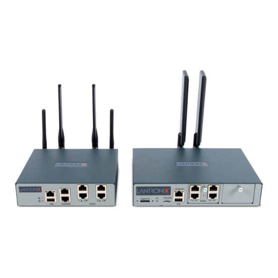
2: Introduction EMG 8500 Hardware Components Figure 2-4 EMG 8500 Unit (front side) Two I/O Module Device DIO Port Micro Console Port Port Bays SD Card USB Port LEDs The appearance and function of the EMG unit will depend upon the type(s) of I/O modules installed in the bays. Figure 2-5 EMG 8500 Unit (back side) Two Connectivity Module Bays Power inlet... -
Page 29: Emg 7500 Hardware Components
2: Introduction EMG 7500 Hardware Components Figure 2-6 EMG 7500 Unit (front side) LEDs Console Port Dual Ethernet One I/O Device Port Module Port USB Port The appearance and function of the EMG unit will depend upon the type of I/O module installed. Figure 2-7 EMG 7500 Unit with Wi-Fi module (back side) Internal LTE cellular Micro... -
Page 30: System Features
2: Introduction System Features This section describes the system features for the EMG edge management gateway. Most features are common to both EMG 8500 and EMG 7500, however, differences between the two models are noted. Access Control The system administrator controls access to attached servers or devices by assigning access rights to up to 128 user profiles. -
Page 31: Device Port Interfaces
The serial RJ45 ports match the RJ45 pinouts of the console ports of many popular devices found in a network environment, and where different can be converted using Lantronix adapters. The RJ45 ports have software reversible pinouts to switch between digital terminal equipment (DTE) and digital communications equipment (DCE) applications. -
Page 32: I/O Modules
Figure 2-11. SFP transceiver modules are provided by users according to fiber mode and brand preferences. Lantronix offers SFP Transceivers (“modules”) for EMG 8500 edge management gateways and SLC 8000 console managers with fiber SFP ports. To learn more, go to https://www.lantronix.com/products/sfp/... -
Page 33: Figure 2-11 Emg 8500 Dual Sfp Connection
2: Introduction The EMG unit will recognize two network connections. One connection must be either Eth1 or SFP1. The second connection must be either Eth2 or SFP2. If a single mode and a multi-mode SFP module are both installed on the EMG unit, the device can be configured to utilize one mode at a time. -
Page 34: Connectivity Modules
2: Introduction Figure 2-12 EMG 8500 LTE Cellular Modem Module SIM card LTE cellular module Wi-Fi The EMG 8500 is equipped with two user swappable connectivity slots on the back of the unit. One Wi-Fi module may be installed in either connectivity slot. See Connectivity Module Installation on page 50. -
Page 35: Front Panel Leds
2: Introduction Front Panel LEDs The front panel LEDs provide quick visual troubleshooting. Both LEDs - Boot Sequence During the boot sequence, the EMG will display the following LEDs: Bootloader Starts - Both LEDs change to green. Kernel Initiation Complete, Applications Start - the top LED remains green, the bottom ... -
Page 36: Figure 2-14 Digital I/O Port
2: Introduction Figure 2-14 Digital I/O Port Pin Number Pin Definition Relay Out Relay In Input1+ Input1- Input2+ Input2- The DIO connector description is provided below. Connector Description Relay Output Output supports 1A 24V Inputs Inputs accept voltage 0 to 30 VDC. Max 30 VDC 2 VDC OFF: Max 0.7 VDC... -
Page 37: 3: Emg 8500 Installation
EMG 8500 Installation This chapter provides a high-level procedure for installing the EMG 8500 followed by more detailed information about the EMG connections and power supplies. Caution: To avoid physical and electrical hazards, please read Appendix B: Safety Information before installing the EMG. EMG 8500 Package Contents The EMG 8500 package includes the following items. -
Page 38: Order Information
For RJ45 ports, you may use a straight-through RJ45 patch cable to connect to Cisco and Sun RJ45 serial console ports. For USB ports, use a cable with a USB Type A connector For information about Lantronix adapters, see Appendix C: Adapters and Pinouts. -
Page 39: Hardware Specifications
4 port USB I/O module. May be used with a USB-to-serial adapter to connect a serial device, if needed. Please contact Lantronix for the list of tested adapters. Caution: USB ports are designed for data traffic only. They are not designed for charging or powering devices. -
Page 40: Physical Installation
3: EMG 8500 Installation Component (continued) Description Front USB Port (1) port, type A, host USB 2.0 (HS, FS, LS) for use with flash drive Front Memory Card (1) Secure Digital (micro SD) memory card slot supporting: SDHC ... -
Page 41: Rack Mount Installation
3: EMG 8500 Installation To configure the EMG unit using a dumb terminal or a computer with terminal emulation, connect the terminal or PC to the front panel EMG console port. See Connecting Terminals (on page 47). 5. Connect the power cord to power on the unit. See Power Input (on page 48). -
Page 42: Wall Mount Installation
3: EMG 8500 Installation Wall Mount Installation Figure 3-5 shows the wall mount and keyhole mount configuration. Figure 3-5 EMG 8500 Wall Mount Dimensions (1) Wall mount (2) Keyhole mount Wall Mount and Keyhole Mount Instructions Walls Requiring Anchors These instructions are for mounting the EMG to walls made of solid concrete, block, brick, or plasterboard. - Page 43 3: EMG 8500 Installation Walls Not Requiring Anchors These instructions are for mounting the EMG to walls made of solid wood at least two (2) inches thick. (1) Wall mount: 1. Locate the place where you want to mount the unit and mark four holes using your EMG mount as a guide for the screws.
-
Page 44: Connecting To A Device Port
1. Connect one end of the cable to the device port. 2. Connect the other end of the cable to an RJ45 serial console port on the serial device or use a Lantronix serial console adapter to connect it to other port types. Notes: Device Port Commands to enable or disable reverse pinouts through the CLI. -
Page 45: Modular Expansion For I/O Module Bays
3: EMG 8500 Installation To connect to a USB device port: 1. Connect the USB type A connector of a USB cable to a device port. 2. Connect the other end of the USB cable to a USB console port. Figure 3-8 shows a sample I/O module installation with one 4-port USB I/O module in Bay 1 and one 4-port RJ45 I/O module in Bay 2, and how the device ports correspond to the buttons on the... -
Page 46: Connecting To Network Ports
3: EMG 8500 Installation Warning: The EMG must be powered off when installing or replacing the modules. Not powering off the device before changing the module will void the manufacturer warranty. Table 3-9 Available I/O Module Configurations for EMG 8500 Connecting to Network Ports The EMG network ports, 10/100/1000 Base-T Ethernet, allow remote access to the attached devices and the system administrative functions. -
Page 47: Connecting Terminals
No flow control To connect the console port to a terminal or computer with terminal emulation, Lantronix offers optional adapters that provide a connection between an RJ45 jack and a DB9 or DB25 connector. The console port is configured as DTE (non-reversed RJ45). See... -
Page 48: Power Input
3: EMG 8500 Installation Note: The Device ID can be found on the product label on the unit or in the boot messages on the console. Note: For security purposes, we recommend that you change the default password and choose a strong password. Power Input The EMG has a DC input jack connector for applying 9 to 30V DC. -
Page 49: I/O Module Installation
3: EMG 8500 Installation I/O Module Installation The EMG module port configuration can be changed by adding or replacing I/O modules in the I/O module bays. Warning: The EMG must be powered off when installing or replacing the modules. Not powering off the device before changing the module will void the manufacturer warranty. -
Page 50: Connectivity Module Installation
3: EMG 8500 Installation 6. Tighten the screw on the module with your fingers. Be careful not to over tighten it. 7. To verify the new module is recognized, connect power to the EMG, wait for it to boot, and log into the web manager. - Page 51 3: EMG 8500 Installation 5. The module will sit flush with the EMG chassis. 6. Tighten the screw on the module with your fingers. Be careful not to over tighten it. 7. Insert and screw in the antennas to the module with your fingers. 8.
-
Page 52: Modem Installation
3: EMG 8500 Installation Modem Installation Note: Modem installation information applies when the dial up modem module is installed in the EMG unit. Caution: TO REDUCE THE RISK OF FIRE, USE ONLY NO. 26 AWG OR LARGER (e.g., 24 AWG) UL LISTED OR CSA CERTIFIED TELECOMMUNICATION LINE CORD. -
Page 53: 4: Emg 7500 Installation
Order Information To view order information, part numbers and extended support options, go to https:// www.lantronix.com/products/lantronix-emg/#tab-order-now. User Supplied Items To complete your installation you will need the following items: Medium size Phillips screwdriver to install the mounting brackets to the EMG unit, if applicable ... -
Page 54: Hardware Specifications
4 port USB I/O module. May be used with a USB-to-serial adapter to connect a serial device, if needed. Please contact Lantronix for the list of tested adapters. Caution: USB ports are designed for data traffic only. They are not designed for charging or powering devices. -
Page 55: Physical Installation
4: EMG 7500 Installation Component (continued) Description Temperature Operating: 0 to 50°C (32 to 122°F) Storage: -20 to 80°C (-4 to 176°F) Relative Humidity Operating: 10% to 90% non-condensing Storage: 10% to 90% non-condensing Front USB Port (1) port, type A, host USB 2.0 (HS, FS, LS) for use with flash drive ... -
Page 56: Rack Mount Installation
4: EMG 7500 Installation Rack Mount Installation Figure 4-3 shows two possible rack mount configurations. Figure 4-4 shows the rack mount screw placement. Figure 4-3 EMG 7500 Rack Mount Configurations Figure 4-4 EMG 7500 Rack Mount Screw Placement 1. Attach the brackets on the sides of the EMG unit using a screwdriver and the screws provided with the mounting kit. -
Page 57: Wall Mount Installation
4: EMG 7500 Installation Wall Mount Installation Figure 4-5 shows the wall mount and keyhole mount configuration. Figure 4-5 Wall Mount Configuration Wall Mount and Keyhole Mount Instructions Walls Requiring Anchors These instructions are for mounting the EMG to walls made of solid concrete, block, brick, or plasterboard with anchors. -
Page 58: Connecting To A Device Port
1. Connect one end of the cable to the device port. 2. Connect the other end of the cable to an RJ45 serial console port on the serial device or use a Lantronix serial console adapter to connect it to other port types. Notes:... -
Page 59: Figure 4-8 Emg 7500 (Front Side)
4: EMG 7500 Installation Pin Number Description Ground Ground RXD (input) DSR (input) CTS (input) Table 4-7 Device Port - Reverse Pinout Enabled (Default) Pin Number Description CTS (input) DSR (input) RXD (input) Ground Ground TXD (output) DTR (output) RTS (output) Figure 4-8 shows the front side of an EMG 7500 with a 4-port RJ45 device port module. -
Page 60: Connecting To Network Ports
No flow control To connect the console port to a terminal or computer with terminal emulation, Lantronix offers optional adapters that provide a connection between an RJ45 jack and a DB9 or DB25 connector. The console port is configured as DTE (non-reversed RJ45). See Appendix C: Adapters and for more information. -
Page 61: Power Input
4: EMG 7500 Installation Power Input The EMG has a DC input jack connector for applying 9 to 30 VDC. The EMG ships with an external AC (90W, 100-240V, 50/60 Hz) 12 VDC power supply. (See EMG 7500 Package Contents on page 53.) Warning: Risk of serious electric shock! Disconnect the power cord before... -
Page 62: Modem Installation
4: EMG 7500 Installation Modem Installation Note: Modem installation information applies when the dial up modem module is installed in the EMG unit. Caution: TO REDUCE THE RISK OF FIRE, USE ONLY NO. 26 AWG OR LARGER (e.g., 24 AWG) UL LISTED OR CSA CERTIFIED TELECOMMUNICATION LINE CORD. -
Page 63: 5: Quick Setup
DHCP. If you have connected Eth1 to the network, and Eth1 is able to acquire an IP address, you can view this IP address by running the Lantronix Provisioning Manager application. If Eth1 cannot acquire an IP address, you cannot use Telnet, SSH, or the web interface to run Quick Setup. -
Page 64: Lantronix Provisioning Manager
1. Launch Lantronix Provisioning Manager: 2. If this is the first time you have launched Lantronix Provisioning Manager, you may need to proceed through an initial setup. 3. Locate the EMG in the device list. The device’s firmware version, serial number, IP address, and MAC address will be shown. -
Page 65: Figure 5-2 Quick Setup
5: Quick Setup Note: If the Device ID is not set, the default system password is the last 8 characters of the serial number. Figure 5-2 Quick Setup 4. To accept the defaults, select the Accept default Quick Setup settings checkbox on the top portion of the page and click the Apply button at the bottom of the page. -
Page 66: Network Settings
The host name becomes the prompt in the command line interface. Domain If desired, specify a domain name (for example, support.lantronix.com). The domain name is used for host name resolution within the EMG. For example, if abcd is specified for the SMTP server, and mydomain.com is specified for the domain, if abcd cannot be resolved, the EMG unit attempts to resolve abcd.mydomain.com... -
Page 67: Date & Time Settings
5: Quick Setup Date & Time Settings Date & Time Setting Description Change Date/Time Select the checkbox to manually enter the date and time at the EMG unit’s location. Date From the drop-down lists, select the current month, day, and year. Time From the drop-down lists, select the current hour and minute. -
Page 68: Method #2 Quick Setup On The Command Line Interface
5: Quick Setup Figure 5-4 Home Method #2 Quick Setup on the Command Line Interface If the EMG does not have an IP address, you can connect a dumb terminal or a PC running a terminal emulation program (VT100) to access the command line interface. (See Connecting Terminals on page 47.) If the unit has an IP address, you can use SSH or Telnet to connect to the... -
Page 69: Figure 5-5 Beginning Of Quick Setup Script
The host name becomes the prompt in the command line interface. Domain If desired, specify a domain name (for example, support.lantronix.com). The domain name is used for host name resolution within the EMG unit. For example, if abcd is specified for the SMTP server, and mydomain.com is specified for the domain, if abcd cannot be resolved, the EMG attempts to resolve abcd.mydomain.com for... -
Page 70: Figure 5-6 Quick Setup Completed In Cli
After you complete the Quick Setup script, the changes take effect immediately. Figure 5-6 Quick Setup Completed in CLI Welcome to the Lantronix Edge Management Gateway Model Number: EMG851000 Quick Setup will now step you through configuring a few basic settings. -
Page 71: Next Step
5: Quick Setup For a list of commands, type 'help'. [emgfcf0]> Next Step After completing quick setup on the EMG, you may want to configure other settings. You can use the web page or the command line interface for configuration. For information about the web and the command line interfaces, go to Chapter 6: Web and ... -
Page 72: 6: Web And Command Line Interfaces
Web and Command Line Interfaces The EMG offers a web interface (Web Manager) and a command line interface (CLI) for configuring the EMG unit. Note: Chapter 5: Quick Setup for instructions on configuring basic network settings using the Web Manager and CLI quick setup. Web Manager A Web Manager allows the system administrator and other authorized users to configure and manage the EMG using most web browsers (Firefox, Chrome, Safari or Internet Explorer web... -
Page 73: Figure 6-2 Sample Dashboard
6: Web and Command Line Interfaces Options: Below each tab are options for specific types of settings. Note: Only those options for which the currently logged-in user has rights display. Figure 6-2 Sample Dashboard Dashboard The Dashboard buttons allow you to view and configure EMG ports and interfaces. The appearance of the dashboard will differ according to the I/O and connectivity modules installed in the EMG and the type of network interface installed. -
Page 74: Logging In
Icons: The icon bar above the Main Menu has icons that display the following: Home page. Information about the EMG unit and Lantronix contact information. Configuration site map. Status of the EMG. Help Button: Provides online Help for the specific web page. -
Page 75: Web Page Help
6: Web and Command Line Interfaces 1. Click the Logout button located on the upper left part of any Web Manager page. You are brought back to the login screen when logout is complete. Web Page Help To view detailed information about an EMG web page: 1. -
Page 76: Logging Out
6: Web and Command Line Interfaces 2. Enter your EMG password and press Enter. Logging Out To log out of the EMG command line interface, type logout and press Enter. Command Syntax Commands have the following format: <action> <category> <parameter(s)> where <action>... -
Page 77: General Cli Commands
The following commands relate to the CLI itself. To configure the current command line session: set cli scscommands <enable|disable> Allows you to use Lantronix Secure Console Server (SCS)-compatible commands as shortcuts for executing commands: Note: Settings are retained between CLI sessions for local users and users listed in the remote users list. -
Page 78: Table 6-4 Cli Keyboard Shortcuts
6: Web and Command Line Interfaces show history To clear the command history: set history clear To view the rights of the currently logged-in user: show user Note: For information about user rights, see Chapter 14: User Authentication. Table 6-4 CLI Keyboard Shortcuts Keyboard Shortcut Description Control + [a]... -
Page 79: 7: Networking
Networking This chapter explains how to set the following network settings for the EMG using the web interface or the CLI: Network Port Settings Cellular Modem Settings Wireless Settings IP Filter Routing VPN Settings Security ... -
Page 80: Network Port Settings
7: Networking Network Port Settings Network parameters determine how the EMG unit interacts with the attached network. Use this page to set the following basic configuration settings for the network ports (Eth1 and Eth2). The EMG supports the following types of network interfaces: RJ-45 ports, as one of the user-selectable active ports on the EMG. -
Page 81: Figure 7-1 Network > Network Settings (1 Of 2)
7: Networking To enter settings for one or both network ports: 1. Click the Network tab and select the Network Settings option. The Network > Network displays. Settings (1 of 2) Network > Network Settings (2 of 2) Figure 7-1 Network > Network Settings (1 of 2) The SFP NIC Info &... -
Page 82: Figure 7-2 Network > Network Settings (2 Of 2)
7: Networking Figure 7-2 Network > Network Settings (2 of 2) EMG™ Edge Management Gateway User Guide... -
Page 83: Ethernet Interfaces (Eth1 And Eth2)
7: Networking Figure 7-3 Network Settings > SFP NIC Information & Diagnostics 2. Enter the following information: Ethernet Interfaces (Eth1 and Eth2) Note: Configurations with the same IP subnet on multiple interfaces (Ethernet or PPP) are not currently supported. Eth1 Settings Disabled: If selected, disables the network port. - Page 84 7: Networking IPv6 Address Address of the port in IPv6 format. (Static) Note: The EMG supports IPv6 connections for the following services: the web, SSH, Telnet, remote syslog, SNMP, NTP, LDAP, Kerberos, RADIUS, TACACS+, connections to device ports, and diagnostic ping. IPv6 addresses are written as 8 sets of 4-digit hexadecimal numbers separated by colons.
-
Page 85: Hostname & Name Servers
Domain If desired, specify a domain name (for example, support.lantronix.com). The domain name is used for host name resolution within the EMG unit. For example, if abcd is specified for the SMTP server, and mydomain.com is specified for the domain, if abcd cannot be resolved, the EMG attempts to resolve abcd.mydomain.com for... -
Page 86: Tcp Keepalive Parameters
7: Networking TCP Keepalive Parameters Start Probes Number of seconds the EMG unit waits after the last transmission before sending the first probe to determine whether a TCP session is still alive. The default is 600 seconds (10 minutes). Number of Probes Number of probes the EMG sends before closing a session. -
Page 87: Fail-Over Settings
7: Networking Fail-Over Settings Fail-over Gateway An alternate IP address of the router for this network, to be used if an IP address IP Address usually accessible through the default gateway fails to return one or more pings. Note: Note: the fail-over gateway is not supported when DHCP is used on the primary interface, as fail-back needs a consistent IP address to use for updating the routing table. - Page 88 7: Networking Fail-over Port The network interface to use for fail-over. The Fail-over Gateway IP Address should either be accessible via this interface or assigned directly to this interface. Select Eth2 (the default), Cellular if a Cellular modem FRU is installed, WLAN if a Wi-Fi FRU is installed or Internal Modem if a Internal modem is installed.
-
Page 89: Fail-Over Cellular Gateway Configuration
For internal cellular modems (EMG models only), see Cellular Modem. Select an integrated external device to be used as the fail-over gateway. Currently the Lantronix PW XC HSPA+ Cellular Gateway and the Sierra Wireless ES450 Cellular Gateway are supported. When using an internal cellular modem as the fail- over gateway, the Fail-over Device should be set to None. -
Page 90: Advanced Cellular Gateway Configuration
The login may have up to 32 characters, and the password may have up to 64 characters. The Admin Password displays the current password masked. Default login credentials of the Lantronix PW HSPA+: Admin login name: admin Admin password: PASS... -
Page 91: Fail-Over Cellular Gateway Firmware
7: Networking Fail-Over Cellular Gateway Firmware Note: The HSPA+ or Sierra fail-over device must be selected in order for you to be able to update the firmware. Update Firmware Select this option to update firmware on the HSPA+ gateway or the Sierra gateway. (check box) The Functional Firmware file and the Radio Firmware file (required for the Sierra gateway only) will be transferred to the EMG using the method selected by the... -
Page 92: Ethernet Counters
7: Networking Ethernet Counters Network > Network Settings (1 of 2) page displays statistics for each of the EMG Ethernet ports since boot-up. The system automatically updates them. Note: For Ethernet statistics for a smaller time period, use the diag perfstat command. -
Page 93: Cellular Modem Settings
7: Networking Cellular Modem Settings The EMG supports the use of one internal LTE cellular modem installed in the EMG unit. The Cellular Settings web page allows the user to configure parameters that determine how the EMG cellular modem network behaves, and to update the cellular modem firmware. To complete the Cellular Settings page: 1. -
Page 94: Cellular Interface
7: Networking 2. Enter the following information: Cellular Interface Cell Settings Disabled: If selected, disables the cellular interface. Default is enabled for DHCP. Obtain from DHCP: Acquires IP address and subnet mask from DHCP. If the cellular modem is configured for DHCP and is used as the Fail-over Gateway, when the IP address of the cellular modem changes, the IP address of the Fail-over Gateway will be automatically updated to be the same as the new cellular modem IP address. - Page 95 7: Networking Link State: the modem interface link state Packet Data Connection State: the cellular data connection state Cellular Counters: the number of bytes received and transferred through the cellular interface Revision: the modem firmware version MEID: the modem equipment identifier ...
-
Page 96: Cellular Modem Commands
7: Networking Network Auth Mode: the authentication mode (PAP, CHAP or none) configured on the cellular modem Roaming: the roaming state configured on the cellular modem FW 1 / FW 2 / FW 3 / FW 4 / Max FW images / Active FW image: the firmware images that are ... -
Page 97: Wireless Settings
7: Networking Wireless Settings Wireless Overview Wireless networking is supported on EMG models only. The EMG can be configured as a wireless station (client) or an access point (AP), but not both simultaneously. Both configurations act as a network interface with a single IP address assigned to it, supporting the same applications that are accessible over the other network interfaces. - Page 98 7: Networking 802.1X is an enterprise class access protocol for protecting networks via authentication. There are three components to 802.1X authentication: A supplicant, or client, which requires authentication (the EMG). An authenticator, or access point, which acts as a proxy for the client, and restricts the client's ...
-
Page 99: Wireless Client Settings
7: Networking EAP Protocol TTLS PEAP FAST LEAP Feature Authentication Mutual Mutual Mutual Mutual Mutual attributes Deployment Difficult Moderate Moderate Moderate Moderate difficulty (because of client certificate deployment) WiFi Security Very High High High High High (when strong passwords are used) Wireless Client Settings The EMG can be configured as a wireless client or an access point. -
Page 100: Figure 7-5 Network > Wireless Settings
7: Networking Figure 7-5 Network > Wireless Settings EMG™ Edge Management Gateway User Guide... - Page 101 7: Networking 2. Enter the following information: Wireless Mode Select the mode that WiFi should operate in. Wireless Client: If selected, enables the EMG to act as a wireless client of a WLAN network. In order to connect to a WLAN network, a WLAN profile for that network needs to exist and be enabled.
- Page 102 7: Networking Interface Counters This table shows statistics for data received by and transferred from the wireless client interface. Wireless Interface Log Click the View Wireless Interface Log link to see diagnostic information for the wireless client. WLAN Profiles In order to connect to a WLAN network, a WLAN profile for that network needs to exist and be enabled.
-
Page 103: Figure 7-6 Network > Wireless Settings > Wlan Profiles
7: Networking Figure 7-6 Network > Wireless Settings > WLAN Profiles 3. To add a new profile click Add Profile, or to edit an existing profile, select a profile and click View/Edit Profile button. 4. Enter the following information: Profile Name Profile name, up to 32 characters long. - Page 104 7: Networking Security Suite Select the security suite used by the profile: None: Select this to connect to a WLAN network with no security, e.g. an open network that does not require a security token or password. WEP: Select this to connect to a WLAN network that uses Wired Equivalent Privacy security.
- Page 105 7: Networking WPA/WPA2 Security If WPA2/WPA Mixed Mode security suite is selected, these Parameters authentication parameters can be selected and configured: Authentication: Select PSK for a connection where the same key must be configured on both on the EMG side and on the access point side, or IEEE 802.1X for a connection that is authenticated with a RADIUS server that is part of the network.
- Page 106 7: Networking IEEE 802.1X Parameters, PEAP: Protected EAP uses server-side public key certificates to continued authenticate the EMG with a RADIUS server. PEAP authentication creates an encrypted TLS tunnel between the EMG and the server. The exchange of information is encrypted and stored in the tunnel ensuring the user credentials are kept secure.
-
Page 107: Wireless Access Point Settings
7: Networking IEEE 802.1X Parameters, PEAP Configuration: Enter a User Name and Password that can be continued authenticated by the RADIUS server. The User Name and Password can be up to 63 characters long, and all printable characters are supported. Select the PEAP Inner Authentication used in the TLS tunnel, which can be EAP-MSCHAPv2, EAP-TLS or EAP-MD5. -
Page 108: Figure 7-7 Network > Wireless Settings > Access Point Settings
7: Networking Figure 7-7 Network > Wireless Settings > Access Point Settings 3. Enter the following information: State Displays the current state of the access point. Enabled: If selected, enables the access point to scan for wireless clients. The default is enabled. The access point cannot be enabled if the wireless client is enabled. - Page 109 7: Networking Encryption When the Security Suite is set to WPA or WPA2, this selects the encryption used: CCMP for AES in Counter mode with CBC-MAC (preferred), TKIP for Temporal Key Integrity Protocol, or Any for both CCMP and TKIP. Passphrase/Retype Passphrase If WPA or WPA2 is selected for the Security Suite, enter the password to connect to the access point.
-
Page 110: Ip Filter
7: Networking IP Filter IP filters (also called a rule set) act as a firewall to allow or deny an individual MAC address or individual or a range of IP addresses, ports, and protocols. When a network connection is configured to use an IP filter, all network traffic through that connection is compared, in order, to the rules of that filter. -
Page 111: Enabling Ip Filters
7: Networking 3. From the Interface drop-down list, select the desired network interface and click the Map Ruleset button. The Interface and rule set display in the IP Filter Mappings table. To delete a mapping: 1. Click the Network tab and select the IP Filter option. The Network >... -
Page 112: Configuring Ip Filters
7: Networking Configuring IP Filters The administrator can add, edit, delete, and map IP filters. Note: A configured filter has no effect until it is mapped to a network interface. See Mapping Rulesets on page 110. To add an IP filter: 1. - Page 113 7: Networking Subnet Mask Specify a subnet mask to determine how much of the address should apply to the filter. Example: 255.255.255.255 to specify the whole address should apply. MAC Address Specify a single MAC address to act as a filter. Example: 10:7d:1a:33:5c:e1 Protocol From the drop-down list, select the type of protocol through which the filter will...
-
Page 114: Updating An Ip Filter
7: Networking Updating an IP Filter To update an IP filter rule set: 1. From the Network > IP Filter page, the administrator selects the IP filter rule set to be edited and clicks the Edit Ruleset button to return to the Network >... -
Page 115: Routing
7: Networking Routing The EMG allows you to define static routes and, for networks using Routing Information Protocol (RIP)-capable routes, to enable the RIP protocol to configure the routes dynamically. To configure routing settings: 1. Click the Network tab and select the Routing option. The following page displays: Figure 7-10 Network >... -
Page 116: Routing Commands
7: Networking Note: To display the routing table, status or specific report, see the section, Status/Reports on page 349. Routing Commands Go to Routing Commands to view CLI commands which correspond to the web page entries described above. VPN Settings This page can be used to create a Virtual Private Network (VPN) tunnel to the EMG for secure communication between the EMG unit and a remote host or gateway. - Page 117 7: Networking MyVPNConn[1]: IKE proposal: 3DES_CBC/HMAC_MD5_96/PRF_HMAC_MD5/ MODP_1024 MyVPNConn{1}: INSTALLED, TUNNEL, reqid 1, ESP in UDP SPIs: c6b71deb_i 95f877ec_o MyVPNConn{1}: 3DES_CBC/HMAC_MD5_96/MODP_1024, 131 bytes_i (1 pkt, 93s ago), 72 bytes_o (1 pkt, 94s ago), rekeying in 7 hours MyVPNConn{1}: 172.28.28.188/32 === 10.3.0.0/24 10.81.101.0/24 10.81.102.0/24 10.81.103.0/24 The EMG loads a subset of the available strongSwan...
-
Page 118: Figure 7-11 Network > Vpn (1 Of 2)
7: Networking To set up a VPN connection: 1. Click the Network tab and select the VPN option. The following page displays: Figure 7-11 Network > VPN (1 of 2) EMG™ Edge Management Gateway User Guide... -
Page 119: Figure 7-12 Network > Vpn (2 Of 2)
7: Networking Figure 7-12 Network > VPN (2 of 2) 2. Enter the following: Enable VPN Tunnel Select to create a tunnel. Disabling this option will terminate any currently running tunnel. Note: The VPN peer that sends the first packet in tunnel bringup is the initiator or client;... - Page 120 7: Networking Remote Subnet(s) One or more allowed subnets behind the remote host, expressed in CIDR notation (IP address/mask bits). If multiple subnets are specified, the subnets should be separated by a comma. Up to 10 local subnets supported. Configured subnets of the peers may differ, the protocol narrows it to the greatest common subnet.
- Page 121 7: Networking IKE Negotiation The Internet Key Exchange (IKE) protocol is used to exchange security options between two hosts who want to communicate via IPSec. The first phase of the protocol authenticates the two hosts to each other and establishes the Internet Security Association Key Management Protocol Security Association (ISAKMP SA).
- Page 122 7: Networking ESP Encryption The type of encryption, 3DES , AES, AES192 or AES256, used for encrypting the data sent through the tunnel. Any can be selected if the two sides can negotiate which type of encryption to use. Note: If ESP Encryption, Authentication and DH Group are set to Any, default cipher suite(s) will be used.
- Page 123 7: Networking Authentication The type of authentication used by the host on each side of the VPN tunnel to verify the identity of the other host. For RSA Public Key, each host generates a RSA public-private key pair, and shares its public key with the remote host. The RSA Public Key for the EMG (which has 4096 bits) can be viewed at either the web or CLI.
- Page 124 7: Networking Certificate Authority for A certificate can be uploaded to the EMG unit for peer authentication. The Local Peer certificate for the local peer is used to authenticate any remote peer to the EMG, and contains a Certificate Authority file, a public certificate file, and a Certificate File for Local private key file.
- Page 125 7: Networking Mode Config In remote access scenarios, it is highly desirable to be able to push configuration information such as the private IP address, a DNS server's IP address, and so forth, to the client. This option defines which mode is used: pull where the config is pulled from the peer (the default), or push where the config is pushed to the peer.
- Page 126 7: Networking Custom ipsec.conf A custom ipsec.conf file can be uploaded to the EMG. This file can include Configuration any of the strongSwan options which are not configurable from the UIs. The ipsec.conf file should include one section which conn <Tunnel Name> defines the tunnel parameters.
-
Page 127: Sample Ipsec.conf Files
7: Networking To see the X.509 Certificates for the local peer and the remote peer, select the View X.509 Certificates link. Sample ipsec.conf Files Sample ipsec.conf files are provided for a variety of tunnel setups and peers. In all examples, any left options are for the console manager/local side of the tunnel, and any right options are for the remote side of the tunnel. - Page 128 7: Networking Cisco ASA5525x Pre-Shared Key / IKEv1 This configuration is an example of a remote access connection to a Cisco ASA5525 VPN server / responder. EMG configuration The pre-shared key needs to be configured via the console manager UI. conn ASA5525 keyexchange=ikev1 ike=aes-sha1-modp1536!
- Page 129 7: Networking crypto ipsec security-association pmtu-aging infinite crypto map site2site 10 match address asa-router-vpn set pfs group5 set peer 192.168.1.204 set ikev1 transform-set ipsecvpn crypto map site2site interface outside crypto ikev1 enable outside crypto ikev1 policy 10 authentication pre-share encryption aes hash sha group 5 lifetime 86400...
- Page 130 7: Networking Cisco configuration interface GigabitEthernet0/0 nameif outside security-level 0 ip address 192.168.1.130 255.255.255.0 interface GigabitEthernet0/3 nameif inside security-level 100 ip address 192.168.3.130 255.255.255.0 object-group network local-network network-object 192.168.3.0 255.255.255.0 network-object 192.168.3.250 255.255.255.255 object-group network remote-network network-object 192.168.0.0 255.255.255.0 network-object 192.168.0.222 255.255.255.255 access-list asa-router-vpn extended permit ip object-group local-network object-group remote-network access-list ASA-SLC-ACCESS extended permit ip object-group local-network...
- Page 131 7: Networking Cisco ISR 2921 Pre-Shared Key / XAUTH / IKEv2 This configuration is an example of a remote access connection to a Cisco ISR2921 VPN server / responder. Console manager configuration The pre-shared key needs to be configured via the console manager UI. conn ISR2921 keyexchange=ikev2 ike=aes-sha2_384-modp1536!
-
Page 132: Vpn Commands
7: Networking group 2 crypto isakmp policy 5 encr 3des authentication pre-share group 5 crypto isakmp policy 10 lifetime 120 crypto isakmp key cisco123 address 192.168.1.100 crypto ipsec transform-set ISR esp-3des esp-sha384-hmac mode tunnel crypto map CM 10 ipsec-isakmp set peer 192.168.1.100 set transform-set ISR set ikev2-profile IKEv2_Profile match address VPN-TRAFFIC... -
Page 133: Security
7: Networking Security The EMG supports a security mode that complies with the FIPS 140-2 standard. FIPS (Federal Information Processing Standard) 140-2 is a security standard developed by the United States federal government that defines rules, regulations and standards for the use of encryption and cryptographic services. - Page 134 7: Networking cryptography) must use a RSA public key of 2048, 3072 or 4096 bits, with the SHA2 hashing algorithm. SSH Keys exported by the console manager use a RSA public key of 2048, 3072 or 4096 bits, with the SHA2 (SHA256) hashing algorithm. SNMP: only SNMPv3 can be used, and insecure algorithms (DES, MD5, SHA1) cannot be used.
-
Page 135: Figure 7-13 Network > Security
7: Networking Algorithm Usage Key Sizes HMAC DRBG Random number generator V (160/224/256/384/512 bits) and Key (160/224/256/384/512 bits) CTR DRBG (AES) Random number generator V (128 bits) and Key (AES 128/192/256 bits) Figure 7-13 Network > Security To enable FIPS: 1. -
Page 136: Performance Monitoring
7: Networking Performance Monitoring The EMG supports Performance Monitoring probes for analyzing network performance. Probes for DNS Lookup, HTTP Get, ICMP Echo, TCP Connect, UDP Jitter and UDP Jitter VoIP are supported. Up to 15 different probes can be configured. Each probe will run a series of operations, each of which sends a series of packets to a destination host. -
Page 137: Figure 7-14 Network > Perf Monitoring
7: Networking To manage or view status for a Performance Monitoring probe: 1. Click the Network tab and select the Perf Monitoring option. The following page displays. Figure 7-14 Network > Perf Monitoring 2. In the upper section of the page, modify the global Performance Monitoring settings: Number of operations Specifies the number of operation set files to keep for each probe. - Page 138 7: Networking UDP Echo Responder Starts the UDP Echo responder on the port configured in UDP Port to reply to UDP echo packets. The EMG UDP Echo responder supports one UDP echo sender. When the UDP Echo responder is enabled, the EMG will verify that the responder UDP port is not being used by any other EMG processes, including port 1967 which is reserved for the UDP Jitter responder.
-
Page 139: Performance Monitoring - Add/Edit Probe
7: Networking Performance Monitoring - Add/Edit Probe Performance Monitoring - Add/Edit Probe web page allows a user to add a new Performance Monitoring probe or edit an existing Performance Monitoring probe. To add a new probe or edit an existing probe: 1. - Page 140 7: Networking 3. Modify the probe settings: Probe Type Select from one of the available probe types: DNS Lookup - Performs a DNS lookup on the hostname specified in the Destination Host using the Name Server. By default port 53 is always used as the Destination Port.
- Page 141 7: Networking Data Size The size in bytes to use for the payload portion of the packet - this size is in addition to the IPv4 header and the TCP, UDP or ICMP header. Any additional space in the packet that is not used by the protocol will be padded with random data that can be used for data verification (see below).
-
Page 142: Performance Monitoring - Results
7: Networking Performance Monitoring - Results The Performance Monitoring - Operations page displays all of the operations that have been saved for a selected probe. The probe ID and name are shown at the top of the web page. From this page, the user may select any operation to view its round trip time (RTT) results, or the accumulated statistics for all round trip times in an operation. - Page 143 7: Networking Accumulated Statistics A summary of all round trip time and any error conditions is displayed. The display will vary for non-jitter and jitter results. For example, non-jitter accumulated results will show: Latest Accumulated Statistics Probe 1/ICMP, operation icmp_190709_154501.dat: Operation Type: ICMP Echo to 172.19.100.17, Ethernet Port: both 10 packets sent 500 ms apart, timeout 200 ms...
-
Page 144: Table 7-16 Error Conditions Detected By Probes
7: Networking Positive Min/Avg/Max: 0/0/0 msec Positive Number Of/Sum of All/Sum of All Squared: 0/0/0 msec Negative Min/Avg/Max: 0/0/0 msec Negative Number Of/Sum of All/Sum of All Squared: 0/0/0 msec Number of Successes: 10 Number of Errors: 0 Lost Packet: 0 (0%) Out of Sequence: 0 Late Arrival: 0 Miscellaneous Error: 0... -
Page 145: Performance Monitoring Commands
7: Networking To view results for a Performance Monitoring probe: 1. Click the Network tab and select the Perf Monitoring option. The Network > Perf Monitoring page displays. 2. Select a probe from the table in the lower part of the page and select the Operations link. The Performance Monitoring - Operations page displays. -
Page 146: Fqdn List
7: Networking FQDN List Use the FQDN List (FQDN stands for fully qualified domain name) to add static hostname entries to the local hosts table so that the EMG can resolve hostnames that are not resolved via DNS. To add/edit/delete hosts: 1. -
Page 147: 8: Services
Identify a Simple Mail Transfer Protocol (SMTP) server. Configure an audit log. View the status of and manage the EMGs on the Secure Lantronix network. Set the date and time. Configure NFS and CIFS shares. -
Page 148: System Logging
8: Services Figure 8-1 Services > SSH/Telnet/Logging 2. Enter the following settings: System Logging Alert Levels Select one of the following alert levels from the drop-down list for each message category: Off: Disables this type of logging. Error: Saves messages that are output because of an error. ... -
Page 149: Audit Log
8: Services Diagnostics Messages concerning system status and problems. General Any message not in the categories above. Remote Servers The IPv4 or IPv6 address of the remote server(s) where system logs are stored. (#1 and #2) The system log is always saved to local EMG storage. It is retained through EMG unit reboots for files up to Other Log Size (see below). -
Page 150: Telnet
8: Services Timeout Data If idle connection timeouts are enabled, this setting indicates the direction of data used Direction to determine if the connection has timed out. Select the type of data direction: Both Directions Incoming Network Outgoing Network ... -
Page 151: Ssh Commands
See the MIB definition file for details. The console manager MIB definition file and the top level MIB file for all Lantronix products is accessible from the SNMP web page. The SLC8000 and EMG share the same MIB definition file, although not every object in the MIB applies to both models. -
Page 152: Figure 8-2 Services > Snmp
8: Services Figure 8-2 Services > SNMP 2. Enter the following: Enable Agent Enables or disables the Simple Network Management Protocol (SNMP) agent, which allows read-only access to the system. Disabled by default. EMG™ Edge Management Gateway User Guide... - Page 153 8: Services Top Level MIB Click the link to access the top level MIB file for all Lantronix products. (link) EMG MIB (link) Click the link to access the EMG MIB definition file for EMGs. EMG MON MIB Click the link to access the EMG monitor MIB definition file for EMGs.
-
Page 154: V1/V2C Communities
8: Services Trap Version When traps are sent, which SNMP version to use when sending the trap: v1, v2c or v3. The default is v2c. NMS #1 (or #2) When SNMP is enabled, an NMS (Network Management System) acts as a central server, requesting and receiving SNMP-type information from any computer using SNMP. -
Page 155: V3 User Read-Write
8: Services Passphrase/ Passphrase associated with the password for a user with read-only authority. Up to 20 Retype characters. If this is not specified it will default to the v3 Read-Only Password. Passphrase V3 User Read-Write User Name SNMP v3 is secure and requires user-based authorization to access objects. -
Page 156: Nfs And Smb/Cifs
8: Services NFS and SMB/CIFS Use the page if you want to save configuration and logging data onto Services > NFS & SMB/CIFS a remote NFS server, or export configurations by means of an exported CIFS share. Mounting an NFS shared directory on a remote network server onto a local EMG directory enables the EMG to store device port logging data on that network server. -
Page 157: Smb/Cifs Share
8: Services NFS Mounts Remote Directory The remote NFS share directory in the format: nfs_server_hostname or ipaddr:/exported/path Local Directory The local directory on the EMG on which to mount the remote directory. The EMG unit creates the local directory automatically. Read-Write If enabled, indicates that the EMG can write files to the remote directory. -
Page 158: Secure Lantronix Network
To directly access the web interface for a secure Lantronix device: 3. On the Secure Lantronix Network page, click the IP address of a specific secure Lantronix device to open a new browser page with the web interface for the selected device. -
Page 159: Figure 8-5 Ip Address Login Page
1. Make sure that Web Telnet or Web SSH is enabled for the specific device. 2. On the Secure Lantronix Network page, click the SSH or Telnet link in the SSH/Telnet to CLI column directly beside the device you would like to access. -
Page 160: Browser Issues
Secure Lantronix Page Click the Services tab, then click the Secure Lantronix Network link (see Figure 8-4.) Select the port you want to configure. Enabled port numbers are in bright green boxes and will allow you to select either a WebSSH or a WebTelnet session. -
Page 161: Troubleshooting Browser Issues
5. To delete an IP address from the IP Address List, select the address and click the Delete IP Address button. 6. Click the Apply button. When the confirmation message displays, click Secure Lantronix Network on the main menu. The Services >... - Page 162 "EMGXYZ.lantronix.com", and the unit website is being accessed in a browser with "https:// EMGXYZ.lantronix.com", the unit needs to be configured with a name server that will allow the unit to perform a reverse lookup on the IP address associated with EMGXYZ.lantronix.com. Failure to perform a reverse lookup on a name may result in name mismatch errors in the browser when it attempts to open the Web SSH or Web Telnet window.
-
Page 163: Web Ssh/Telnet Copy And Paste
Enter, the content will be sent to the Web SSH or Web Telnet window. Secure Lantronix Network Commands Go to SLC Network Commands (on page 443) to view CLI commands which correspond to the web page entries described above. -
Page 164: Date And Time
8: Services Date and Time Use the Date and Time Settings page to specify the local date, time, and time zone at the EMG location, or enable the EMG unit to use NTP to synchronize with other NTP devices on your network. -
Page 165: Date And Time Commands
8: Services 2. Enter the following: Change Date/Time Select the checkbox to manually enter the date and time at the location. Date From the drop-down lists, select the current month, day, and year. Time From the drop-down lists, select the current hour and minute. Time Zone From the drop-down list, select the appropriate time zone. -
Page 166: Web Server
8: Services Web Server The Web Server supports all versions of the TLS protocol, but due to security concerns, does not support any versions of the SSL protocol. The Web Server page allows the system administrator Configure attributes of the web server. ... - Page 167 8: Services 2. Enter the following fields: Timeout Select No to disable Timeout. Select Yes, minutes (5-120) to enable timeout. Enter the number of minutes (must be between 30 and 120 minutes) after which the EMG web session times out. The default is 30. Note: If a session times out, refresh the browser page and login to a new web session.
-
Page 168: Admin Web Commands
8: Services Run Web Server If enabled, the web server will run and listen on TCP ports 80 and 443 (all requests to port 80 are redirected to port 443). By default, the web server is enabled. The web server supports TLS 1.0, TLS 1.1, and TLS 1.2. Due to security vulnerabilities, SSL is not supported. -
Page 169: Figure 8-11 Web Server - Ssl Certificate
8: Services Figure 8-11 Web Server - SSL Certificate 2. If desired, enter the following: Reset to Default To reset to the default certificate, select the checkbox to reset to the default Certificate certificate. Unselected by default. Root Filename Filename of the imported root or intermediate Certificate Authority. If HTTPS is selected as the method for import, the Upload File link will be selectable to upload a Certificate authority. - Page 170 The locality or city for the custom certificate, e.g. "Irvine". Must be at least 2 characters long. Organization Name The organization or company name for the custom certificate, e.g. "Lantronix". Must be at least 2 characters long. Organization Unit The unit name for the custom certificate, e.g. "Engineering" or "Sales". Must be at Name least 2 characters long.
-
Page 171: Services - Web Sessions
Services > Web Server ConsoleFlow ConsoleFlow is a cloud or on-premise portal for the centralized management of multiple Lantronix ITM devices. A browser based interface (including mobile phone app support) allows an administrator to view status, send commands, view logs and charts and update firmware. Each Lantronix device can communicate with the cloud server or on-premise server, sending status updates and responding to commands sent by the server. - Page 172 8: Services Device ID is invalid, the Registration Host name cannot be resolved, or the Registration Host is not reachable. Once registration is successful, Status of Client will display Registered with the date and time of registration. Note that the Registered date/time displayed in the EMG status may be different from the registered date/time shown in the ConsoleFlow web UI.
- Page 173 8: Services the Status of Client. When a script run completes (either for a single manual run or a recurring scheduled run), the status of the script will be retained on the console manager until a new script is initiated from ConsoleFlow and the console manager determines that the maximum number of ConsoleFlow scripts per console manager has been reached;...
-
Page 174: Figure 8-13 Services > Consoleflow
8: Services Figure 8-13 Services > ConsoleFlow 2. Enter the following: ConsoleFlow Client Enables or disables the ConsoleFlow client. This option is enabled by default, unless an EMG is not configured with a Device ID. When the client is enabled, it will attempt to register with the Registration Host. - Page 175 Long description that is displayed in the ConsoleFlow server UI. Device ID The unique device identifier. The ID is 32 alphanumeric characters. The ID may be provisioned using Lantronix Provisioning Manager (LPM). Contact Lantronix Tech Support for more information on LPM. Displays the serial number.
-
Page 176: Consoleflow Commands
8: Services Messaging Host Hostname of the server used for messaging services. The hostname should start with mqtt. Messaging Port The TCP port on the Messaging Host. Defaults to 443. Messaging Services If enabled, TLS is used for messaging. If Validate certificates with HTTPS is Security enabled for the Registration Host, a certificate authority will be used to validate the HTTPS certificates used for TLS. -
Page 177: 9: Usb/Sd Card Port
USB/SD Card Port This chapter describes how to configure storage by using the Devices > USB / SD Card page and CLI. This page can be used to configure the micro SD card or the USB flash drive (thumb drive). The USB flash drive or micro SD card is useful for firmware updates, saving and restoring configurations and for device port logging. -
Page 178: Figure 9-1 Devices > Usb / Sd Card
9: USB/SD Card Port Figure 9-1 Devices > USB / SD Card To configure a USB/SD card storage port: 1. Insert any of the supported storage devices into the USB port or the SD card slot on the front of the EMG unit. 2. -
Page 179: Figure 9-2 Devices > Usb > Configure
9: USB/SD Card Port Figure 9-2 Devices > USB > Configure Figure 9-3 Devices > SD Card > Configure 5. Enter the following fields. Mount Select the checkbox to mount the first partition of the storage device on the EMG unit (if not currently mounted). Once mounted, a USB thumb drive or SD card is used for firmware updates, device port logging and saving/restoring configurations. -
Page 180: Manage Files
9: USB/SD Card Port Unmount To eject the USB thumb drive or SD card from the EMG unit , first unmount the thumb drive or SD card . Select the checkbox to unmount it. Warning: If you eject a thumb drive or SD card from the EMG unit without unmounting it, subsequent mounts of a USB thumb drive or SD card in may fail, and you will need to reboot the device to restore thumb drive or SD card functionality. -
Page 181: Usb Commands
9: USB/SD Card Port Figure 9-4 Firmware and Configurations - Manage Files Note: The Delete, Download, and Rename options are at the bottom of the page (Figure 9-4). 2. To delete a file, click the check box next to the filename and click Delete File. A confirmation message displays. -
Page 182: 10: Device Ports
10: Device Ports This chapter describes how to configure and use an EMG port connected to an external device, such as a server or a modem. This chapter also describes how to configure the console port. describes how to use the web page to connect Chapter 13: Connections Devices >... -
Page 183: I/O Modules
10: Device Ports 3. Clear mode: The user can clear the contents of the device port buffer (set locallog <port> clear buffer command). The administrator and users with local user rights may assign individual port permissions to local users. The administrator and users with remote authentication rights assign port access to users authenticated by NIS, RADIUS, LDAP, Kerberos and TACACS+. -
Page 184: Device Status
10: Device Ports Device Status page displays the status of the EMG ports, the USB port and SD Devices > Device Status card port. Click the Devices tab and select the Device Status option. The following page displays: Figure 10-2 Devices > Device Status Device Ports On the Devices >... -
Page 185: Figure 10-3 Devices > Device Ports
10: Device Ports Figure 10-3 Devices > Device Ports Current port numbering schemes for Telnet, SSH, and TCP ports display on the left. The list of ports on the right includes the individual ports and their current mode. Note: Icons that represent some of the possible modes include: Idle The port is not in use. -
Page 186: Telnet/Ssh/Tcp In Port Numbers
10: Device Ports Telnet/SSH/TCP in Port Numbers Starting Telnet Port Each port is assigned a number for connecting via Telnet. Enter a number (1025- 65528) that represents the first port. The default is 2000 plus the port number. For example, if you enter 2001, port 1 will be 2001 and subsequent 2000 ports are automatically assigned numbers 2001, 2002, and so on. -
Page 187: Device Ports - Settings
10: Device Ports Device Ports - Settings On the page, configure IP and data (serial) settings for individual Device Ports > Settings (1 of 2) ports, and if the port connects to an external modem, modem settings as well. To open the Device Ports - Settings page: 1. -
Page 188: Figure 10-4 Device Ports > Settings (1 Of 2)
10: Device Ports The following page displays: Figure 10-4 Device Ports > Settings (1 of 2) EMG™ Edge Management Gateway User Guide... -
Page 189: Device Port Settings
10: Device Ports Figure 10-5 Device Ports > Settings (2 of 2) 2. Enter the following: Device Port Settings Port Displays number of port; displays automatically. Mode The status of the port; displays automatically. USB Device This field is only displayed for USB ports. If a USB device is connected to the device port, this displays the USB version, speed, and a short type description for the USB device. - Page 190 10: Device Ports Detect Port Name If enabled, the EMG will attempt to detect the hostname of the device connected to the device port, and set the device port name to the detected hostname. Many devices use their hostname or another identifier as the device prompt, and the EMG can extract this name from the prompt using the Detect Name Tokens.
-
Page 191: Ip Settings
10: Device Ports Break Sequence A series of one to ten characters users can enter on the command line interface to send a break signal to the external device. A suggested value is Esc+B (escape key, then uppercase “B” performed quickly but not simultaneously). You would specify this value as \x1bB, which is hexadecimal (\x) character 27 (1B) followed by a B. -
Page 192: Data Settings
10: Device Ports Seconds Enter a value from 1 to 3600 seconds if selecting the Telnet, SSH or TCP Timeout checkbox to the left. The default is 600 seconds. Note: When the Idle Timeout Msg is enabled, the terminal application timeout values for Telnet, SSH and TCP should be set to a value greater than 15 seconds. -
Page 193: Hardware Signal Triggers
10: Device Ports Parity Parity checking is a rudimentary method of detecting simple, single-bit errors. From the drop-down list, select the parity. The default is none. Flow Control A method of preventing buffer overflow and loss of data. The available methods include none, xon/xoff (software), and rts/cts (hardware). -
Page 194: Modem Settings (Device Ports)
Ethernet patch cable, without the need for a rolled cable or adapter. Enabled by default. Note: Applies to serial RJ45 device ports only. All Lantronix serial adapters are intended to be used with Reverse Pinout disabled. USB VBUS For USB Device Ports only. -
Page 195: Modem Settings: Text Mode
10: Device Ports Use Sites Enables the use of site-oriented modem parameters which can be activated by various modem-related events (authentication, outbound network traffic for dial- on-demand connections, etc.). Sites can be used with the following modem states: dial-in, dial-back, dial-on-demand, dial-in & dial-on-demand, dial-back & dial-on-demand, and CBCP server. -
Page 196: Modem Settings: Ppp Mode
10: Device Ports Modem Settings: PPP Mode Negotiate IP Address If the EMG unit and/or the serial device have dynamic IP addresses (e.g., IP addresses assigned by a DHCP server), select Yes. Yes is the default. If the EMG or the modem have fixed IP addresses, select No, and enter the Local IP (IP address of the port) and Remote IP (IP address of the modem). -
Page 197: Port Status And Counters
10: Device Ports From the Apply Settings drop-down box, select none, a group of settings, or All. In to Device Ports, type the device port numbers, separated by commas; indicate a range of port numbers with a hyphen (e.g., 2, 5, 7-10). Note: It may take a few minutes for the system to apply the settings to multiple ports. - Page 198 10: Device Ports This menu allows the administrator to query status and control any of the power supplies that provide power to the device connected to the device port and change the Baud Rate of the device port. Note: The Baud Rate can be configured while connected to a device port by entering the Power Management Sequence.
-
Page 199: Figure 10-7 Device Ports - Power Management
10: Device Ports Figure 10-7 Device Ports - Power Management 3. Enter the following: Power Management A series of one to ten characters that will display the Power Management menu Sequence when connected to the device port. The default value is Esc+P (escape key, then uppercase "P"). -
Page 200: Device Port - Sensorsoft Device
10: Device Ports Outlet For each managed power supply, enter the outlet on the selected RPM. As an aid to selecting the outlet, click the View Outlets button, then select an outlet from the list and click the Select Outlet button. The managed power supply outlet number will be filled in, as well as the managed power supply outlet name if a name is listed for the outlet and one has not already been defined for the managed power supply. -
Page 201: Figure 10-8 Devices > Device Ports - Sensorsoft
10: Device Ports Figure 10-8 Devices > Device Ports - Sensorsoft 4. Select a port and enter or view the following information: Dev Port Displays the number of the EMG port. Device Port Name Displays the name of the EMG port. Curr Temp Current temperature (degrees Celsius) on the device the sensor is monitoring. -
Page 202: Device Port Commands
10: Device Ports Figure 10-9 Sensorsoft Status Device Port Commands Go to Device Port Commands to view CLI commands which correspond to the web page entries described above. Device Commands Go to Device Commands to view CLI commands which correspond to the web page entries described above. -
Page 203: Interacting With A Device Port
10: Device Ports Interacting with a Device Port Once a device port has been configured and connected to an external device such as the console port of an external server, the data received over the device port can be monitored at the command line interface with the connect listen command, as follows: To connect to a device port to monitor it: connect listen deviceport <Port # or Name>... -
Page 204: Device Ports - Logging And Events
10: Device Ports Device Ports - Logging and Events The EMG products support port buffering of the data on the system's device ports as well as notification of receiving data on a device port. Port logging is disabled by default. You can enable more than one type of logging (local, NFS file, token and data detection, SD card, or USB port) at a time. -
Page 205: Token/Data Detection
10: Device Ports Token/Data Detection The system administrator can configure the device log to detect when a user-defined string or number of characters is received from the device, and automatically perform one or more actions: send a message to the system log, send an SNMP trap, send an email alert, send a string to the device, or control one of the power supplies associated with the device. -
Page 206: Token & Data Detection
10: Device Ports Figure 10-10 Devices > Device Ports - Logging & Events 2. Enter the following: Token & Data Detection Token & Data Select to enable token and data detection on the selected device port, with a set of Detection actions that can be enabled if a data trigger occurs. - Page 207 10: Device Ports Byte Threshold The number of bytes of data the port will receive before the EMG unit will capture log data and initiate the selected actions. The default is 100 bytes. In most cases, the console port of your device does not send any data unless there is an alarm condition.
-
Page 208: Local Logging
10: Device Ports Local Logging Local Logging If you enable local logging, each device port stores 256 Kbytes (approximately 400 screens) of I/O data in a true FIFO buffer. Disabled by default. Clear Local Log Select the checkbox to clear the local log. View Local Log Click this link to see the local log in text format. -
Page 209: Logging Commands
10: Device Ports range of port numbers with a hyphen (e.g., 2, 5, 7-10), and separate ranges with commas. 4. To save, click the Apply button. Logging Commands Go to to view CLI commands which correspond to the web page entries Logging Commands described above. -
Page 210: Console Port Commands
10: Device Ports Parity Parity checking is a rudimentary method of detecting simple, single-bit errors. From the drop-down list, select the parity. The default is none. Flow Control A method of preventing buffer overflow and loss of data. The available methods include none, xon/xoff (software), and rts/cts (hardware). -
Page 211: Internal Modem Settings
10: Device Ports Internal Modem Settings This section describes how to configure an internal modem in the EMG. The EMG internal modem is an optional part. If the modem is installed, a message will be displayed when the unit boots: Internal modem installed. -
Page 212: Figure 10-12 Devices > Internal Modem
10: Device Ports Figure 10-12 Devices > Internal Modem 2. Complete or view the following sections: Text Mode Mode. State Indicates whether the internal modem is enabled. When enabling, set the modem to dial-out, dial-in, dial-back, and dial-on-demand. Disabled by default. For more information on the different dialing types, see Modem Dialing States. - Page 213 10: Device Ports Mode The format in which the data flows back and forth. With Text selected, the EMG unit assumes that the modem will be used for remotely logging into the command line. Text mode is only for dialing in. This is the default.
- Page 214 10: Device Ports Dial-back Number Users with Dial-back can dial into the EMG unit and enter their login and password. Once the EMG unit authenticates them, the modem hangs up and dials them back . Select the phone number the modem dials back on: a fixed number or a number associated with their login.
-
Page 215: Internal Modem Commands
10: Device Ports Remote/Dial-out Password for authentication when dialing out to a remote system, or if a remote Password/ Retype system requests authentication from the EMG unit when it dials in. May have up to 20 characters. Restart Delay The number of seconds after the timeout and before the EMG module attempts another connection. -
Page 216: Dio Commands
10: Device Ports State (view only) Displays the current state of the port: on or off. Normal State Defines the typical or normal state of the DIO Input port. This setting is used for Events. 2. Change the following Front Relay port fields: Name The name of the port. -
Page 217: Xmodem
10: Device Ports Xmodem The EMG supports using the Xmodem, Ymodem, or Zmodem protocols to send and receive files across serial ports. An Xmodem repository on the EMG holds files that can be sent or have been received. In order to use one of the protocols, the device port that will be used must not be currently in use for any other purpose. - Page 218 10: Device Ports To manage the Xmodem repository, send files or receive files: 1. Click the Devices tab and select the Xmodem option. The Xmodem page displays: 2. To upload a file to the repository, click the Upload File link and upload a file in the window that is displayed.
-
Page 219: Xmodem Commands
10: Device Ports 6. Click the Send File to Device Port button. The send will be initiated, and the Status window can be opened to view the progress of the send. When the Xmodem protocol is used, the user will be prompted when to start the file receive with the message, “Give your local XMODEM receive command now.”... -
Page 220: Host Lists
10: Device Ports Host Lists A host list is a prioritized list of SSH, Telnet, and TCP hosts available for establishing incoming modem connections or for the connect direct command on the CLI. The EMG unit cycles through the list until it successfully connects to one. To add a host list: 1. - Page 221 10: Device Ports Protocol Protocol for connecting to the host (TCP, SSH, or Telnet). Port Port on the host to connect to. Escape Sequence The escape character used to get the attention of the SSH or Telnet client. It is optional, and if not specified, Telnet and SSH use their default escape character.
-
Page 222: Figure 10-14 Devices >View Host Lists
10: Device Ports To view or update a host list: 1. In the Host Lists table, select the host list and click the View Host List button. The list of hosts display in the Hosts box. Figure 10-14 Devices >View Host Lists 2. -
Page 223: Host List Commands
10: Device Ports Escape Sequence The escape character used to get the attention of the SSH or Telnet client. It is optional, and if not specified, Telnet and SSH use their default escape character. For Telnet, the escape character is either a single character or a two-character sequence consisting of '^' followed by one character. -
Page 224: Sites
10: Device Ports Sites A site is a group of site-oriented modem parameters (or modem profile) that can be activated by various modem-related events (authentication on dial-in, outbound network traffic for a dial-on- demand connection, etc.). The site parameters will override parameters that are configured for a modem. - Page 225 10: Device Ports Note: To clear fields in the lower part of the page, click the Reset Site button. Site Id Displays after a site is created. (view only) Site Name Enter a name for the site. Port Select the port: None, Internal Modem, Device Port, or USB Port U1 the site is assigned to.
-
Page 226: Site Commands
10: Device Ports Dial-back Number The phone number to dial on callback for text or PPP dial-back connections. A site must successfully authenticate, have Allow Dial-back enabled and have a Dial-back Number defined in order for the site to be used for callback. Allow Dial-back If enabled, the site is allowed to be used for dial-back connections. -
Page 227: Modem Dialing States
10: Device Ports Modem Dialing States This section describes how each modem state that supports sites operates when sites are enabled. Dial In The EMG waits for a peer to call the EMG unit to establish a text (command line) or PPP connection. -
Page 228: Dial-On-Demand
10: Device Ports remain connected to the EMG unit until they either logout of the CLI session, or (if Timeout Logins is enabled) the CLI session is terminated if it has been idle. For PPP connections, the user will be authenticated via PAP or CHAP (determined by the ... -
Page 229: Dial-Back & Dial-On-Demand
10: Device Ports CHAP Secret match the name and secret sent in the CHAP Challenge response by the PPP peer, (b) Authentication is set to CHAP, and (c) the Port is set to None or matches the port the modem is on. If the remote peer requests PAP or CHAP authentication from the EMG, the Remote/Dial-out Login and Remote/Dial-out Password configured for the modem (not the site) will be provided as authentication tokens. -
Page 230: Cbcp Server And Cbcp Client
10: Device Ports demand connection will be started for each, waiting for IP traffic destined for a remote network. When IP traffic needs to be sent, the EMG unit dials the appropriate Dial-out Number for the site, and if the remote peer requests PAP or CHAP authentication, provides the Dial-out Login and Dial-out Password as authentication tokens. -
Page 231: Key Sequences
10: Device Ports number to use for dial-back. The EMG device will request the type of number defined by CBCP Client Type - either an Admin-defined Number (the CBCP server determines the number to call) or a User-defined Number (the EMG unit will provide the Fixed Dial-back Number as the number to call). -
Page 232: 11: Remote Power Managers
11: Remote Power Managers The EMG supports managing remote power managers (RPMs) for devices from over 140 vendors. The RPM can be either a power distribution unit (PDU) or uninterruptible power source/supply (UPS), and can be managed via SNMP, serial port, network and USB connections. The RPMs web page displays a list of all currently managed RPMs with an overview of their current status, with options to control and view detailed status for each RPM, depending on its supported capabilities. -
Page 233: Figure 11-2 Rpm Shutdown Order
11: Remote Power Managers Notifications Displays the notifications configured for each PDU and UPS. See Figure 11-3. Raw Data Displays a window with all of the information returned by the driver when a query for status is requested. This option is available for all RPMs. -
Page 234: Figure 11-3 Rpm Notifications
11: Remote Power Managers Figure 11-3 RPM Notifications Figure 11-4 RPM Raw Data Log EMG™ Edge Management Gateway User Guide... -
Page 235: Rpms - Add Device
11: Remote Power Managers Figure 11-5 RPM Logs Figure 11-6 RPM Environmental Log RPMs - Add Device The Add Device page assists the administrator with adding a new managed RPM to the EMG configuration. With over 140 different vendors and nearly 1000 different models that are supported, the key to ensuring the EMG can properly manage a PDU or UPS is selecting the right model (with its associated driver) and any required driver options, especially for USB managed devices. -
Page 236: Figure 11-7 Devices > Rpms - Add Device
11: Remote Power Managers Note: Devices > RPMs - Add Device page with the same functionality can also be accessed through the Device Ports > Settings (1 of 2) page by selecting RPM in the Connected dropdown menu. Figure 11-7 Devices > RPMs - Add Device 3. - Page 237 11: Remote Power Managers Model Select the Model in the drop-down menu. The drop-down menu will be populated with models supported for the selected vendor. To the left of each model name is one or two letters in parentheses that indicate the type of control available for the selected model: P - SNMP, S - serial port, U - USB port, N - network.
-
Page 238: Rpms - Manage Device
11: Remote Power Managers Critical Emails If an email address is specified, under critical conditions (see Critical SNMP Traps above), an email notification will be sent to the email address. The Server and Sender configured in the SMTP settings will be used to send the email. - Page 239 11: Remote Power Managers Figure 11-8 RPMs - Manage Device 3. Enter the following: RPM Id (view only) The unique number associated with the RPM. Name Specify the unique name of the RPM (up to 20 characters). Status (view only) The current status of the RPM.
- Page 240 11: Remote Power Managers Current (view only) The total current value for the RPM in Amperes, if this information is provided by the RPM. If the RPM consists of two separate towers or units, each with its own current value, both current values will be displayed, separated by a slash. Input Voltage (view The input voltage for the RPM in Volts, if this information is provided by the RPM.
- Page 241 11: Remote Power Managers Log Status Indicates if the status of the RPM is periodically logged. Select Yes, minutes to log the status periodically and enter a value between 1 and 60 minutes. The logs can be viewed by viewing the RPMs web page and clicking on "Logs". Critical SNMP Traps If enabled, under critical conditions (UPS goes onto battery power, UPS battery is low, UPS forced shutdown in progress, UPS on line power, UPS battery needs to be replaced, RPM is unavailable, communications with RPM lost, communications with...
-
Page 242: Rpms - Outlets
11: Remote Power Managers RPMs - Outlets The Outlets page allows the administrator to view the current status of each individual outlet on an RPM, and change the state of the outlets. Not all RPMs support individual outlet status and control. - Page 243 11: Remote Power Managers continue to run until its battery fails completely, to shutdown just the UPS with the low battery, or to shutdown one or more UPSes. UPS-type RPMs can report the following states: OL - On line power ...
-
Page 244: Optimizing And Troubleshooting Rpm Behavior
11: Remote Power Managers will still be shutdown if another UPS reaches the low battery state and has its Low Battery Action set to Shutdown all UPSes. Shutdown Both EMG UPSes - This setting should only be used on dual-power EMG units ... -
Page 245: Rpm Commands
11: Remote Power Managers Driver Debug Mode - The driver can be run in debug mode at the CLI and the output examined to determine why the driver is not starting or is unable to communicate with the RPM. The CLI command set rpm driver <RPM Id or Name> action debug [level <1|2|3>] will stop any currently running driver and restart the driver in debug mode with output sent to a local file. -
Page 246: 12: Scripts
12: Scripts This chapter describes how to use Scripts to automate tasks performed on the EMG CLI or on device ports. EMG supports the following types of scripts: Interface Scripts which use a subset of the Expect/Tcl scripting language to perform pattern ... -
Page 247: Figure 12-2 Adding Or Editing New Scripts
12: Scripts 2. Click the Add Script button. The page for editing script attributes displays. Figure 12-2 Adding or Editing New Scripts 3. Enter the following script details: Script Name A unique identifier for the script. Type Select Interface for a script that utilizes Expect/Tcl to perform pattern detection ... - Page 248 Services Right to enable and disable system logging, SSH and Telnet logins, SNMP, and SMTP. Secure Lantronix Right to view and manage secure Lantronix units (e.g., EMG or SLC devices) on Network the local subnet. Date/Time Right to set the date and time.
-
Page 249: Figure 12-3 Scripts > Custom Scripts - Scheduler
12: Scripts To view or update a script: 1. In the Scripts table, select the script and click the Edit Script button. The page for editing script attributes displays (see Figure 12-2). 2. Update the script attributes (see To add a script: above). - Page 250 12: Scripts with one schedule): Device Type The device - either the CLI or a Device Port - that the script is connected to. State The state of the script’s schedule. A script must be Enabled in order for the script scheduler to begin running the schedule.
-
Page 251: Script Commands
12: Scripts To delete the completed operations (runs) for a custom script: 1. In the Scripts table, select the script to view operations for, and click Script Operations. 2. The Custom Scripts - Operations page displays, with a list of any results that have been generated for a script, in reverse date/time order. -
Page 252: Batch Script Syntax
12: Scripts Batch Script Syntax The syntax for Batch Scripts is exactly the same as the commands that can be typed at the CLI, with the additions described in this section. The sleep command suspends execution of the script (puts it to 'sleep') for the specified number of seconds. -
Page 253: Interface Script Syntax
12: Scripts Interface Script Syntax This section describes the abbreviated scripting syntax for Interface Scripts. This limited syntax was created to prevent the creation of scripts containing potentially harmful commands. Script commands are divided into three groups: Primary, Secondary and Control Flow. Primary commands provide the basic functionality of a script and are generally the first element on a line of a script, as in: send_user "Password:"... -
Page 254: Primary Commands
12: Scripts Primary Commands These are stand-alone commands which provide the primary functionality in a script. These commands may rely on one or more of the Secondary Commands to provide values for some parameters. The preprocessor will require that these commands appear only as the first element of a command line. -
Page 255: Secondary Commands
12: Scripts Command Description expect, expect_user, command waits for input and attempts to match it against one or expect expect_before, more patterns. If one of the patterns matches the input the corresponding expect_after, (optional) command is executed. All commands have the same syntax: expect expect_background expect {<string 1>... -
Page 256: Table 12-6 Secondary Commands
12: Scripts Table 12-6 Secondary Commands Command Description string string command provides a series of string manipulation operations. The command will only be used with the to generate a value string set command for a variable. There are nine operations provided by the command. -
Page 257: Control Flow Commands
12: Scripts Command Description timestamp This command returns the current time of day as determined by the . The command will only be used in combination with the timestamp set command to produce the value for a variable. Syntax: timestamp <format> where is a quoted string. - Page 258 12: Scripts Command Description if, elseif and else command executes an associated block of commands if its Boolean expression evaluates to TRUE. Each command within the block must be a Primary command. Syntax: if {<Boolean expression>} { command 1 command 2 command n command is used in association with an command - it must...
-
Page 259: Custom Script Syntax
12: Scripts Custom Script Syntax This section describes the scripting syntax for Custom Scripts. The syntax is more flexible than Interactive Script syntax, but still has restrictions to prevent the creation of scripts containing potentially harmful commands. In addition, Custom Scripts can be configured to use command line parameters. - Page 260 12: Scripts clisession. The clisession will not display the Logout Banner as this may interfere with script termination. 5. The script cannot contain commands which spawn or fork other commands, read or write files on the EMG filesystem, or interrogate the EMG filesystem. The list of commands that are not allowed for Expect scripts includes "fork", "open", "exp_open", "exec", "system", "log_file", "pwd".
-
Page 261: Example Scripts
12: Scripts Example Scripts Interface Script—Monitor Port on page 261 Batch Script—EMG CLI on page 264 Expect Custom Script - EMG CLI Session on page 266 Expect Custom Script - EMG Device Port Session on page 268 ... - Page 262 The following is the screen output: emg247]> conn script ex4 deviceport 7 login: Logging in..sysadmin sysadmin Password: PASS Welcome to the Lantronix Edge Management Gateway Model Number: EMG851101 For a list of commands, type 'help'. [EMG251]> show network port 1...
- Page 263 12: Scripts show portcounter deviceport 7 Device Port: 7 Seconds since zeroed: 1453634 Bytes input: 0 Bytes output: 0 Framing errors: 0 Flow control errors: 0 Overrun errors: 0 Parity errors: 0 [ EMG251]> Port Counter Monitor Script Ending..________________________________________________________________________ Login Out..
- Page 264 [emg247]> connect script monport deviceport 7 login: Logging in..sysadmin sysadmin Password: PASS Welcome to the Lantronix Edge Management Gateway Model Number: EMG851101 For a list of commands, type 'help'. [EMG251]> show network port 1 host show network port 1 host...
- Page 265 12: Scripts Device Port: 7 Seconds since zeroed: 1454120 Bytes input: 0 Bytes output: 0 Framing errors: 0 Flow control errors: 0 Overrun errors: 0 Parity errors: 0 [EMG251]> [Current Time:21:25:20] show portcounter deviceport 7 show portcounter deviceport 7 Device Port: 7 Seconds since zeroed: 1454136 Bytes input: 0 Bytes output: 0 Framing errors: 0 Flow...
- Page 266 12: Scripts Expect Custom Script - EMG CLI Session An example of an Expect Custom Script that interacts with an EMG CLI session: #! expect # script to get the current internal temperature of the EMG # accepts one optional command line parameter for location set emgPrompt ">"...
- Page 267 12: Scripts expect { timeout {myprint "Timeout waiting to login"; abortSession 3} "Need to specify username" {myprint "Need to specify -U "; abortSession 4} "*> " {set loggedIn true} exp_send "\n" expect { timeout {myprint "Timeout waiting for CLI prompt"; abortSession 3} -re "\n\r(\\\[\[^\r]*]>)"...
- Page 268 12: Scripts Expect Custom Script - EMG Device Port Session An example of an Expect Custom Script that interacts with a EMG Device Port (in this example a ServerTech PDU is connected to a Device Port): #! expect # Script to get the load of a ServerTech PDU outlet set pduPrompt ">"...
- Page 269 12: Scripts # Wait for the first prompt set loggedIn false while {! $loggedIn} { expect { timeout {myprint "Timeout waiting to login"; abortSession 3} "*CDU: " {set loggedIn true} # Detect the prompt exp_send "\n" expect "are:\r\n" expect "LOGIN\r\n" expect "REMOVE\r\n"...
- Page 270 12: Scripts Expect Custom Script - EMG Device Port Session An example of an Expect Custom Script that interacts with a EMG Device Port (in this example a Cisco server is connected to a Device Port): #! expect # Save a copy of the running config of a Cisco server to a TFTP server # The Cisco server is connected to an EMG device port proc myprint {str} { send_user -- "$str\n"...
- Page 271 12: Scripts set passwordPrompt false set cnt 1 while {! $loggedIn || ! $execMode} { if {$cnt == 5} { myprint "Timeout waiting for > or # prompt" abortSession 4 if {! $passwordPrompt} { send "\r" expect { "*assword: " { send "$enablePassword\r" } ">"...
- Page 272 12: Scripts Python Custom Script - EMG CLI Session An example of a Python Custom Script that interacts with a CLI session: #! python # Script to set the RADIUS authentication settings of the EMG # Sets the first RADIUS server and secret, and enables RADIUS # Note: passing secret as a command line parameter is a security vulnerability # Usage:...
- Page 273 12: Scripts while True: output_str = proc.stdout.readline() if b'RADIUS settings successfully updated' in output_str: break elif b'set radius' not in output_str: # RADIUS command returned an error s1 = str(output_str) s2 = s1.split("\\r")[1] print("RADIUS command returned: " + s2.split("\\n")[0]) proc.stdin.close() proc.terminate() proc.wait() sys.exit(1)
- Page 274 12: Scripts Python Custom Script - EMG CLI Session An example of a Python Custom Script that uses the Pexpect module to interact with the CLI session and the device ports to detect the prompt on any devices connected to the EMG, and set the device port name to be the same as the device prompt: #! python # Script to detect the prompt on a device connected to an EMG device...
- Page 275 12: Scripts loggedIn = True slcPrompt = p.match.group(1).decode('utf-8') if numPorts == 0: print("Cannot determine number of device ports.") p.terminate(True) sys.exit(1) print("Number of device ports:", numPorts) # Terminate the CLI session p.sendline("logout") time.sleep(.500) p.wait() skipPorts = False devicePort = 1 pList = [] if numPorts == 24 or numPorts == 40: # Adjust port numbering for SLC8024 and SLC8040 skipPorts = True...
- Page 276 12: Scripts print("portsession on DP ", devicePort, "unexpectedly terminated.") break elif i == 2: # login prompt p.sendline("sysadmin") p.expect("Password:") p.sendline("PASS") emgDevice = True gotPrompt = True elif i == 3: # error from portsession print(p.match.group(1).decode('utf-8')) p.terminate(True) p.wait() break elif i == 4: # prompt gotPrompt = True # end if while not gotPrompt:...
- Page 277 12: Scripts # Connect to the EMG CLI and set the device port names p=pexpect.spawn('clisession -U sysadmin') loggedIn = False while not loggedIn: i = p.expect([pexpect.TIMEOUT, pexpect.EOF, 'Model Number: SLC80(\d*)\r\n', 'Model Number: SLB882\r\n', '(\[.*>)'], timeout=10) if i == 0: # Timeout print("Timeout waiting to login.") p.terminate(True) sys.exit(1)
- Page 278 12: Scripts Tcl Custom Script - EMG CLI Session An example of a Tcl Custom Script that interacts with a CLI session: #! tcl # Script to get the current internal temperature of the EMG # Accepts one optional command line parameter for location set emgTemp "unknown"...
- Page 279 12: Scripts set gotTemp true puts "Temperature: $emgTemp" puts $io "logout" flush $io exit 0 EMG™ Edge Management Gateway User Guide...
-
Page 280: 13: Connections
13: Connections Chapter 10: Device Ports described how to configure and interact with an EMG port connected to an external device. This chapter describes how to use the Devices > Connections page to connect external devices and outbound network connections (such as Telnet or SSH) in various configurations. -
Page 281: Remote Access Server
13: Connections Remote Access Server In this setup, the EMG is connected to one or more modems by its device ports. Configure the device ports on the Device Ports > Settings (1 of 2) web page by selecting the Dial-in option in the Modem Settings section. -
Page 282: Multiport Device Server
A PC can use the device ports on the EMG unit as virtual serial ports, enabling the ports to act as if they are local ports to the PC. To use the EMG in this setup, the PC requires special software, for example, Com Port Redirector (available on www.lantronix.com) or similar software. Figure 13-4 Multiport Device Server... -
Page 283: Connection Configuration
13: Connections Figure 13-5 Console Server Connection Configuration Note: These are advanced connection settings for specific applications. If the EMG is being used as a console or device server it is unlikely that you will need any of the Connection settings described below. To create a connection: 1. -
Page 284: Figure 13-6 Devices > Connections
13: Connections Figure 13-6 Devices > Connections 2. For a device port, enter the following: Outgoing Select to turn on or turn off the connection timeout: Connection No for no timeout Timeout Yes for a timeout. Specify the number of seconds in the seconds field. ... -
Page 285: Connection Commands
13: Connections Port If the to field is set to Device Port or Modem on Device Port, enter the number of the device port. For all other options, this is the TCP/UDP port number, which is optional for Telnet out and SSH out, but required for TCP Port and UDP Port. Note: If you select Device Port, it must not have command line interface logins enabled or be running a loopback test. -
Page 286: 14: User Authentication
14: User Authentication Users who attempt to log in by means of Telnet, SSH, the console port, or one of the device ports are granted access by one or more authentication methods. The User Authentication page provides a submenu of methods (Local Users, NIS, LDAP, RADIUS, Kerberos, and TACACS+) for authenticating users attempting to log in. -
Page 287: Figure 14-1 User Authentication > Auth Methods
14: User Authentication Figure 14-1 User Authentication > Auth Methods 2. To enable a method currently in the Disabled methods list, select the method and press the left arrow to the left of the list. The methods include: A network naming and administration system developed by Sun Microsystems for smaller networks. -
Page 288: Authentication Commands
14: User Authentication TACACS+ TACACS+ allows a remote access server to communicate with an authentication server to determine whether the user has access to the network. (Terminal Access TACACS+ is a completely new protocol and is not compatible with TACACS or Controller Access Control XTACACS. -
Page 289: User Rights
Device Port Operations Device Port Configuration Reboot/Shutdown Firmware/Configuration Diagnostics and Reports Secure Lantronix Network Web Access Internal Modem RPMs SD Card You cannot deny a user rights defined for the group, but you can add or remove all other rights at any time. -
Page 290: Local And Remote User Settings
14: User Authentication Local and Remote User Settings The system administrator can configure the EMG to use local accounts and remote accounts to authenticate users. 1. Click the User Authentication tab and select the Local/Remote Users option. The following page displays. Figure 14-3 User Authentication >... -
Page 291: Sysadmin Account Default Login Values
14: User Authentication Authenticate only Select the check box to authenticate users listed in the Remote Users list in the remote users who are lower part of the page. Disabled by default. in the remote users list Deny access to remote Select the check box to authenticate remote users whose LDAP group or users assigned to TACACS+ priv_lvl map to an EMG custom group, allow EMG access if matched. -
Page 292: Adding, Editing Or Deleting A User
14: User Authentication the About EMG page or run the CLI admin version command and look for the following in the result:Admin Password Unique to Device: enabled (or disabled). If that string is absent from the result or the result is set to “disabled”, it indicates that the device doesn’t support the device-unique sysadmin password. -
Page 293: Figure 14-4 User Authentication > Local/Remote User Settings
14: User Authentication Figure 14-4 User Authentication > Local/Remote User Settings 2. Enter the following information for the user: Login User ID of selected user. Authentication Select the type of authenticated user: Local: User listed in the EMG database. Remote: User not listed in the EMG database. - Page 294 14: User Authentication Enable for Dial-back Select to grant a local user dial-back access. Users with dial-back access can dial into the EMG unit and enter their login and password. Once the EMG authenticates them, the modem hangs up and dials them back. Disabled by default.
- Page 295 Services Right to enable and disable system logging, SSH and Telnet logins, SNMP, and SMTP. Secure Lantronix Right to view and manage Secure Lantronix units (e.g., EMG, or SLC units) on the Network local subnet. Date/Time Right to set the date and time.
-
Page 296: Shortcut
14: User Authentication Shortcut To add a user based on an existing user: 1. Display the existing user on the User Authentication > Local/Remote Users page. The fields in the top part of the page display the current values for the user. 2. -
Page 297: Nis
14: User Authentication The system administrator can configure the EMG to use NIS to authenticate users attempting to log in to the EMG unit through the Web, SSH, Telnet, or the console port. If NIS does not provide port permissions, you can use this page to grant device port access to users who are authenticated through NIS. - Page 298 14: User Authentication 2. Enter the following: Enable NIS Displays selected if you enabled this method on the Authentication Methods page. If you want to set up this authentication method but not enable it immediately, clear the checkbox. Note: You can enable NIS here or on the first User Authentication page. If you enable NIS here, it automatically displays at the end of the order of precedence on the User Authentication page.
-
Page 299: Nis Commands
Services Right to enable and disable system logging, SSH and Telnet logins, SNMP, and SMTP. Secure Lantronix Right to view and manage secure Lantronix units (e.g., EMG, or SLC units) on the Network local subnet. Date/Time Right to set the date and time. -
Page 300: Ldap
14: User Authentication LDAP The system administrator can configure the EMG to use LDAP to authenticate users attempting to log in using the Web, Telnet, SSH, or the console port. LDAP allows EMG unit users to authenticate using a wide variety of LDAP servers, such as OpenLDAP and Microsoft Active Directory. -
Page 301: Figure 14-6 User Authentication > Ldap
14: User Authentication Figure 14-6 User Authentication > LDAP 2. Enter the following: Enable LDAP Displays selected if you enabled this method on the first User Authentication page. If you want to set up this authentication method but not enable it immediately, clear the checkbox. - Page 302 Attribute use to search for a name (ie, "msmith") or a Distinguished Name (ie, "uid=msmith,ou=People,dc=lantronix,dc=com"). Select either Name or DN as appropriate for the LDAP server. If nothing is specified for the group membership attribute, the EMG unit will use "memberUID" for name and "uniqueMember" for DN.
- Page 303 14: User Authentication Encrypt Messages Select Start TLS or SSL to encrypt messages between the EMG unit and the LDAP server. If Start TLS is selected, the port will automatically be set to 389 and the StartTLS extension will be used to initiate a secure connection; if SSL is selected, the port will automatically be set to 636 and a SSL tunnel will be used for LDAP communication.
-
Page 304: Ldap Commands
Services Right to enable and disable system logging, SSH and Telnet logins, SNMP, and SMTP. Secure Lantronix Right to view and manage secure Lantronix units (e.g., EMG, or SLC devices) on Network the local subnet. Date/Time Right to set the date and time. -
Page 305: Radius
14: User Authentication RADIUS The system administrator can configure the EMG to use RADIUS to authenticate users attempting to log in using the Web, Telnet, SSH, or the console port. Users who are authenticated through RADIUS are granted device port access through the port permissions on this page. - Page 306 14: User Authentication 2. Enter the following: Enable RADIUS Displays selected if you enabled this method on the User Authentication page. If you want to set up this authentication method but not enable it immediately, clear the checkbox. Note: You can enable RADIUS here or on the first User Authentication page. If you enable RADIUS here, it automatically displays at the end of the order of precedence on the User Authentication page.
- Page 307 Services Right to enable and disable system logging, SSH and Telnet logins, SNMP, and SMTP. Secure Lantronix Right to view and manage Secure Lantronix units (e.g., EMG, or SLC units) on the Network local subnet. Date/Time Right to set the date and time.
-
Page 308: Radius Commands
FreeRADIUS server, the dictionary will need be updated with the Lantronix definition by including the contents below in a file named dictionary.lantronix, and including it in the RADIUS server dictionary definitions by adding the appropriate $INCLUDE directive to the main dictionary file. - Page 309 VENDOR Lantronix 244 BEGIN-VENDOR Lantronix ATTRIBUTE Lantronix-User-Attributes 1 string END-VENDOR Lantronix Once this is complete, the users file can be updated to include the Lantronix VSA for any user: myuser Auth-Type := Local, User-Password == "myuser_pwd" Reply-Message = "Hello, %u", Lantronix-User-Attributes = "data 1-4 listen 1-6 clear 1-4...
-
Page 310: Kerberos
14: User Authentication Kerberos Kerberos is a network authentication protocol that provides strong authentication for client/server applications by using secret-key cryptography. The system administrator can configure the EMG to use Kerberos to authenticate users attempting to log in using the Web, Telnet, SSH, or the console port. Users who are authenticated through Kerberos are granted device port access through the port permissions on this page. - Page 311 14: User Authentication 2. Enter the following: Enable Kerberos Check box displays as checked if this method is enabled on the User Authentication page. If you want to set up this authentication method but not enable it immediately, clear the checkbox. Note: You can enable Kerberos here or on the first User Authentication page.
-
Page 312: Kerberos Commands
Services Right to enable and disable system logging, SSH and Telnet logins, SNMP, and SMTP. Secure Lantronix Right to view and manage secure Lantronix units (e.g.,EMG, or SLC units) on the Network local subnet. Date/Time Right to set the date and time. -
Page 313: Tacacs
14: User Authentication TACACS+ Similar to RADIUS, the main function of TACACS+ is to perform authentication for remote access. The EMG supports the TACACS+ protocol (not the older TACACS or XTACACS protocols). The system administrator can configure the EMG unit to use TACACS+ to authenticate users attempting to log in using the Web, Telnet, SSH, or the console port. -
Page 314: Figure 14-9 User Authentication > Tacacs
14: User Authentication Figure 14-9 User Authentication > TACACS+ 2. Enter the following: Enable TACACS+ Displays selected if you enabled this method on the User Authentication page. If you want to set up this authentication method but not enable it immediately, clear the checkbox. - Page 315 14: User Authentication Authentication The type of service used to pass the authentication tokens (e.g., login and Service password) between the EMG and the TACACS+ server. Options are: ASCII Login (login and password are transmitted in clear, unencrypted text), PPP/PAP (login and password are transmitted in clear, unencrypted text via a PAP protocol packet), and PPP/CHAP (the TACACS+ server sends a challenge that consists of a session ID and an arbitrary challenge string, and the user name and password...
-
Page 316: Tacacs+ Commands
Services Right to enable and disable system logging, SSH and Telnet logins, SNMP, and SMTP. Secure Lantronix Right to view and manage secure Lantronix units (e.g., EMG, or SLC units) on the Network local subnet. Date/Time Right to set the date and time. -
Page 317: Groups
14: User Authentication Groups The EMG has 3 pre-defined groups: Administrators, Power Users, and Default Users. Custom groups can also be created; each custom group is a set of user attributes and permissions. Local Users and Remote Users defined on the EMG unit can be assigned to one of the pre-defined groups or a custom group. -
Page 318: Figure 14-10 User Authentication > Groups
14: User Authentication Figure 14-10 User Authentication > Groups 2. Enter the following: Group Name Enter a name for the group. Listen Ports The ports users are able to monitor using the connect listen command. Data Ports The ports users are able to monitor and interact with using the connect direct command. - Page 319 Services Right to enable and disable system logging, SSH and Telnet logins, SNMP, and SMTP. Secure Lantronix Right to view and manage Secure Lantronix units (e.g., EMG, or SLC units) on the Network local subnet. Date/Time Right to set the date and time.
-
Page 320: Group Commands
14: User Authentication To view or update a group: 1. In the Groups table, select the group and click the View Group button. The group attributes and permissions will be displayed in the lower section of the page. 2. Modify the group attributes and permissions and click the Edit Group button. To delete a group: 1. -
Page 321: Ssh Keys
14: User Authentication SSH Keys Overview The EMG can import and export SSH keys to facilitate shared key authentication for all incoming and outgoing SSH connections. By using a public/private key pair, a user can access multiple hosts with a single passphrase, or, if a passphrase is not used, a user can access multiple hosts without entering a password. - Page 322 14: User Authentication ..++.o. o. .. oo o o+ooo |.+o.o.*oo o . |.oo= = .S= |. + = o . | o o + o |+ * ..E |+= *o .. +----[SHA256]-----+ It is recommended to use secure bit sizes (-b); for example, at least 2048 bits for RSA keys. The passphrase is optional, and will be used to encrypt the key.
-
Page 323: Imported Keys (Ssh In)
14: User Authentication Figure 14-11 User Authentication > SSH Keys 2. Enter the following information: Imported Keys (SSH In) Host & User Associated with Key These entries are required in the following cases: The imported key file does not contain the host that the user will be making an SSH ... -
Page 324: Exported Keys (Ssh Out)
14: User Authentication The EMG local user login for the connection is different from the user name the key was generated from or is not included in the imported key file, or The imported key file contains multiple keys; in this case, each key must include the user ... -
Page 325: Ssh Server/Host Keys
14: User Authentication Host and Login for Export Export via Select the method (SCP, SFTP, FTP, HTTPS, or Copy/Paste) of exporting the key to the remote server. Copy/Paste, the default, requires no other parameters for export. Host IP address of the remote server to which the EMG will SCP, SFTP or FTP the public key file. -
Page 326: Figure 14-12 Current Host Keys
14: User Authentication Figure 14-12 Current Host Keys 2. View or enter the following: Select the All Keys checkbox to reset all default key(s), or select one or more Reset to Default Host checkboxes to reset defaults for RSA, or DSA keys. All checkboxes are unselected by default. -
Page 327: Ssh Commands
14: User Authentication Path Path of the directory where the host key will be stored. User ID to use to SCP or SFTP the file. Login Password / Password to use to SCP or SFTP the file. Retype Password 3. Click the Apply button. 4. -
Page 328: Custom Menus
14: User Authentication Custom Menus Users can have custom user menus as their command line interface, rather than the standard CLI command set. Each custom user menu can contain up to 50 commands ('logout' is always the last command). Instead of typing each command, the user enters the number associated with the command. - Page 329 14: User Authentication Note: To clear fields in the lower part of the page, click the Clear Custom Menu button. Menu Name Enter a name for the custom menu. Title Enter an optional title which will be displayed about the menu at the CLI. Nicknames Select to enable nicknames to be displayed in the menu instead of the commands.
-
Page 330: Custom User Menu Commands
14: User Authentication To view or update a custom menu: 1. In the Custom Menus table, select the custom menu and click the View Custom Menu button. The custom menu attributes appear in the lower part of the page. 2. Update the menu attributes following the instructions for adding a menu above. 3. -
Page 331: 15: Maintenance
15: Maintenance The system administrator performs maintenance activities and operates the EMG using the options for the Maintenance tab and additional commands on the command line interface. Firmware & Configurations The Firmware & Configuration page allows the system administrator to: Configure the FTP, SFTP, or TFTP server that will be used to provide firmware updates and ... - Page 332 15: Maintenance b. Option TFTP Server IP/150 and Boot Filename/67 - if both of these are received, they will be used, and all other DHCP options will be ignored. c. Option TFTP Server IP or Name/66 and Boot Filename/67 - if both of these are received, they will be used.
- Page 333 15: Maintenance cd ztp-cert mkdir newcerts cp /etc/ssl/openssl.cnf . export OPENSSL_CONF=/root/ztp-cert/openssl.cnf b. Under the CA_default section in openssl.cnf, change the directory where everything is kept to ".": [ CA_default ] dir = . # Where everything is kept c. The openssl.cnf sections [ req ] and [ req_distinguished_name ] can be updated with specific options for certificate requests, or the defaults can be used.
-
Page 334: Https Push Configuration Restore
15: Maintenance d. The server.key file and server.crt file output in these steps can be installed in the web server that will provide the ZTP configuration file. The certificate can be verified (e.g. view the root CA, algorithms, validity date and CN, etc) at anytime with the command: openssl x509 -noout -text -in server.crt 4. -
Page 335: Factory Reset With External Storage Device
15: Maintenance url="https://myemg.company.com/ cfgupdate.htm?login=sysadmin&password=PASS&config=all&comment=Update myemg.company.com with default configuration" curl --insecure --request POST --form "file=@/home/users/admin/current- emgcfg.tgz" "$( echo $url | sed 's/ /%20/g' )" If an HTTPS Push Config command is accepted and initiated by the EMG, the EMG will respond with "Configuration restore initiated;... -
Page 336: Figure 15-1 Maintenance > Firmware & Configurations
15: Maintenance To configure settings: 1. Click the Maintenance tab. The following page displays. Figure 15-1 Maintenance > Firmware & Configurations EMG™ Edge Management Gateway User Guide... -
Page 337: Internal Temperature
To view a log of all prior firmware updates, click the Firmware Update Log link. The name of the firmware update file downloaded from the Lantronix web site. Firmware Filename A key for validating the firmware file. The key is provided with the firmware file (32 hex characters). -
Page 338: Boot Banks And Bootloader Settings
15: Maintenance Load Firmware Via From the drop-down list, select the method of loading the firmware. Options are FTP, TFTP, HTTPS, NFS, USB, and SD Card. FTP is the default. If you select HTTPS, the Upload File link becomes active. Select the link to ... -
Page 339: Load Firmware Via Options
15: Maintenance Load Firmware Via Options Note: Prior to firmware update, the current configuration is saved to the Local Disk location with the name "before_MMDDYY_HHMM". HTTPS Click Upload File to update the EMG firmware. NFS Mounted Dir Select the NFS mounted directory from the drop-down menu. USB Port Click to select USB port. - Page 340 15: Maintenance Location for Save, If you selected to save or restore a configuration, select one of the following Restore, or Manage options: Manage: This link allows you to view and delete all configurations saved to the selected location. This feature is available for the Local Disk, NFS Mounts, CIFS Share, USB, and SD Card locations.
-
Page 341: Manage Files
15: Maintenance Figure 15-2 Network > Firmware/Config > Manage Manage Files The Manage Files web page allows you to view the firmware and configuration files saved to the selected location and rename, download or delete any of the files. This feature is available for the Local Disk, NFS Mounts, CIFS Share, USB, and SD card locations. -
Page 342: System Logs
15: Maintenance System Logs page allows you to view various system logs. (See Maintenance > System Logs Chapter 8: Services on page 147 for more information about system logs.) You can also clear logs on this page. To view system logs: 1. -
Page 343: System Log Commands
Figure 15-4 View System Logs From a queried system log (e.g., Figure 15-4), you may email this information to a specific individual or to Lantronix Technical Support. See Emailing Logs and Reports (on page 352). To clear system logs: 1. From the Maintenance >... -
Page 344: Audit Log
15: Maintenance Audit Log page displays a log of all actions that have changed the Maintenance > Audit Log configuration of the EMG. The audit log is disabled by default. Use the Services > SSH/Telnet/ Logging page (Chapter 8: Services) to enable the audit log and to configure its maximum size. Each entry in the log file contains a date/time stamp, user login, and the action performed by the user. -
Page 345: Email Log
15: Maintenance Email Log page displays a log of all attempted emails. The log file can be Maintenance > Email Log cleared from here. The email log is saved through EMG reboots. 1. Click the Maintenance tab and select the Email Log option. The following page displays: Figure 15-6 Maintenance >... -
Page 346: Diagnostics
15: Maintenance Diagnostics page provides methods for diagnosing problems such as network Maintenance > Diagnostics connectivity and device port input/output problems. You can use equivalent commands on the command line interface. 1. Click the Maintenance tab and select the Diagnostics option. The following page displays: Figure 15-7 Maintenance >... - Page 347 15: Maintenance IPv6 Neighbor The IPv6 Neighbor table is used to view a list of neighbor's IPv6 addresses on the same Table network, and their corresponding MAC addresses. Netstat Displays network connections. If you select the checkbox, select the TCP or UDP protocol, or select All for both protocols to control the output of the Netstat report.
-
Page 348: Figure 15-8 Diagnostics Output
15: Maintenance iPerf Select to start an iPerf3 server or client to measure network throughput. The server will run in “one-off” mode. This means that it will handle one client connection and then terminate. The server will wait indefinitely for the client to connect. The client will time out if a connection is not made to a server within 15 seconds. -
Page 349: Diagnostic Commands
15: Maintenance 5. To email this report, follow the instructions in Emailing Logs and Reports (on page 352). Diagnostic Commands Go to to view CLI commands which correspond to the web page entries Diagnostic Commands described above. Status/Reports On this page, you can view the status of the EMG ports and power supplies and generate a selection of reports. - Page 350 15: Maintenance Port Status Displays the status of each device port: mode, user, any related connections, and serial port settings. Port Counters Displays statistics related to the flow of data through each device port. IP Routes Displays the routing table. Connections Displays all active connections for the EMG unit: Telnet, SSH, TCP, UDP, device port, and modem.
-
Page 351: Status Commands
15: Maintenance Figure 15-10 Generated Status/Reports 4. To email these report(s), follow the instructions in Emailing Logs and Reports (on page 352). Status Commands Go to Status Commands to view CLI commands which correspond to the web page entries described above. EMG™... -
Page 352: Emailing Logs And Reports
15: Maintenance Emailing Logs and Reports The following logs and reports can be directly emailed to a specific individual or to Lantronix Technical Support directly from the log page: System Log (Figure 15-4) Audit Log (Figure 15-5) Email Log... -
Page 353: Figure 15-12 About Emg
15: Maintenance Figure 15-12 About EMG EMG™ Edge Management Gateway User Guide... -
Page 354: Events
15: Maintenance Events On this page, you can define what action you want to take for events that Maintenance > Events may occur in the EMG unit. 1. Click the Maintenance tab and select the Events option. The following page displays: Figure 15-13 Maintenance >... - Page 355 15: Maintenance Outlet When the trigger is set to RPM Load over Threshold, select the outlet that will be monitored for a current that exceeds a defined threshold. The RPM needs to support providing a current level for the selected outlet as part of its status information.
-
Page 356: Events Commands
15: Maintenance Events Commands Go to Events Commands to view CLI commands which correspond to the web page entries described above. Banners Maintenance > Banners page allows the system administrator to customize text messages that display to users. To configure banner settings: 1. -
Page 357: Administrative Banner Commands
15: Maintenance SSH Banner The text to display when a user logs into the EMG via SSH, prior to authentication. May contain up to 1024 characters. Single quote and double quote characters are not supported. Blank by default. Note: To create more lines use the \n character sequence. 3. -
Page 358: 16: Application Examples
16: Application Examples Each EMG has multiple serial ports and two network ports. Each serial port can be connected to the console port of an IT device. Using a network port (in-band) or a modem (out-of-band) for dial- up connection, an administrator can remotely access any of the connected IT devices using Telnet or SSH. -
Page 359: Telnet/Ssh To A Remote Device
16: Application Examples Telnet/SSH to a Remote Device The following figure shows a Sun server connected to port 2 of the EMG. Figure 16-2 Remote User Connected to a SUN Server via the Console Manager In this example, the sysadmin would: 1. - Page 360 16: Application Examples NFS File Logging: disabled Directory to log to: <none> Max number of files: 10 Max size of files: 2048 2. Change the baud to 57600 and disable flow control: [EMG]> set deviceport port 2 baud 57600 flowcontrol none Device Port settings successfully updated.
-
Page 361: Dial-In (Text Mode) To A Remote Device
16: Application Examples Dial-in (Text Mode) to a Remote Device This example shows a phone line connection to the internal modem of the EMG, and a Sun server connected to a device port. You can configure the modem for text mode dial-in, so a remote user can dial into the modem using a terminal emulation program and access the Sun server. - Page 362 16: Application Examples 5. Connect to the SUN Unix server using the direct command. [EMG]> connect direct deviceport 2 SunOS 5.7 login: frank Password: Last login: Wed Jul 14 16:07:49 from computer Sun Microsystems Inc.SunOS 5.7Generic October 1998 SunOS computer 5.7 Generic_123485-05 sun4m sparc SUNW,SPARCstation-20 6.
-
Page 363: Local Serial Connection To Network Device Via Telnet
16: Application Examples Local Serial Connection to Network Device via Telnet This example shows a terminal device connected to an EMG device port, and a Sun server connected over the network to the EMG device. When a connection is established between the device port and an outbound Telnet session, users can access the Sun server as though they were directly connected to it. - Page 364 16: Application Examples Max number of files: 10 Max size of files: 2048 2. Change the serial settings to match the serial settings for the vt100 terminal - changes baud to 57600 and disables flow control: [EMG]> set deviceport port 2 baud 57600 flowcontrol none Device Port settings successfully updated.
-
Page 365: 17: Command Reference
17: Command Reference After an introduction to using commands, this chapter lists and describes all of the commands available on the EMG command line interface accessed through Telnet, SSH, or a serial connection. The commands are in alphabetical order by category. Introduction to Commands Following is some information about command syntax, command line help, and tips for using commands. -
Page 366: Command Line Help
17: Command Reference Action Category connect bidirection|direct|global|listen|restart|script|terminate |unidirection diag arp|arp6|internals|iperf|lookup|loopback|netstat|nettrace|pe rfstat|ping|ping6|sendpacket|top|traceroute|usb|wlan admin banner|chip|clear|config|eeprom|events|feature|firmware|ftp| memory|quicksetup|reboot|shutdown|site|version|web Terminates CLI session. logout Command Line Help For general Help and to display the commands to which you have rights, type: help For general command line Help, type: help command line For release notes for the current firmware release, type: help release... -
Page 367: Administrative Commands
17: Command Reference When the number of lines displayed by a command exceeds the size of the window (the default is 25), the command output is halted until the user is ready to continue. To display the next line, press Enter, and to display the page, press the space bar. You can override the number of lines (or disable the feature altogether) with the set cli command. - Page 368 17: Command Reference admin banner ssh Syntax admin banner ssh <Banner Text> Description Configures the banner that displays prior to SSH authorization. admin banner welcome Syntax admin banner welcome <Banner Text> Description Configures the banner displayed before the user logs in. Note: To go to the next line, type \n and press Enter.
- Page 369 17: Command Reference admin config rename <Config Name> location <local|nfs|cifs|usb|sdcard> [usbport <U1>] [nfsdir <NFS Mounted Directory>] Description Deletes or renames a configuration. admin config factorydefaults Syntax admin config factorydefaults [savesshkeys <enable|disable>] [savesslcert <enable|disable>] [preserveconfig <Config Params to Preserve>] [savescripts <enable|disable>] <Config Params to Preserve>...
- Page 370 "01WFA" for WiFi FRU "01DMA" for DialUp Modem FRU Description Commands for EEPROM IDs. These commands should only be used under the direction of Lantronix Technical Support. Show/Update EEPROM ID of the attached FRU. EMG™ Edge Management Gateway User Guide...
- Page 371 17: Command Reference Not all EMG models will have all slots. admin firmware bootbank Syntax admin firmware bootbank <1|2> Description Sets the boot bank to be used at the next EMG reboot. admin firmware bootcount Syntax admin firmware bootcount <0|1> Description Configures bootcount parameter that control how many times the EMG has failed to boot.
- Page 372 17: Command Reference admin firmware highrestimers Syntax admin firmware highrestimers <enable|disable> Description Enables high resolution timers required for Performance Monitoring or disables high resolution timers (the default). Changing this setting requires a reboot in order for the change to take effect. admin firmware watchdog Syntax admin firmware watchdog <disable|180-1800 seconds>...
- Page 373 17: Command Reference Description Clears the firmware update log. admin ftp password Syntax admin ftp password Description Sets the FTP server password and prevent it from being echoed. admin ftp server Syntax admin ftp server <IP Address or Hostname> [login <User Login>] [path <Directory>] Description Sets the FTP/TFTP/SFTP server used for firmware updates and configuration save/restore.
- Page 374 17: Command Reference Description Creates a swap space from an external storage device. admin memory swap delete Syntax admin memory swap delete Description Deletes the swap space from an external storage device. admin quicksetup Syntax admin quicksetup Description Runs the quick setup script. admin reboot Syntax admin reboot...
- Page 375 17: Command Reference Description Configures information about the site where the EMG is located. admin version Syntax admin version Description Displays current hardware and firmware information. admin web certificate import Syntax admin web certificate import via <sftp|scp> [rootfile <Cert Authority File>] certfile <Certificate File>...
- Page 376 17: Command Reference admin web certificate show Syntax admin web certificate show Description Displays the web server SSL certificate. admin web group Syntax admin web group <Local or Remote Group Name> Description Configures the group that can access the web. admin web server Syntax admin web server <enable|disable>...
- Page 377 17: Command Reference admin web terminate Syntax admin web terminate <Session ID> Description Terminates a web session. admin web show Syntax admin web show [viewcipherlist <enable|disable>] Description Displays the current sessions, with optional extra sessions or current ciphers. admin web banner Syntax admin web banner Description...
- Page 378 Description Restarts the web server. Warning: The following admin chip commands should only be used under the direction of Lantronix Technical Support. admin chip resetmodem Description Resets the internal modem chip in key system chips. Syntax admin chip resetmodem admin chip reseti2cmux EMG™...
-
Page 379: Audit Log Commands
17: Command Reference Description Resets the I2C Mux chip in key system chips. Syntax admin chip reseti2cmux admin chip resetsfp ethport <1|2> Description Resets the SFP chip in key system chips. Syntax admin chip resetsfp ethport <1|2> Audit Log Commands show auditlog Syntax show auditlog [command|user|clear]... -
Page 380: Kerberos Commands
17: Command Reference Description Sets ordering of authentication methods. Local Users authentication is always the first method used. Any methods omitted from the command are disabled. show auth Syntax show auth Description Displays authentication methods and their order of precedence. show user Syntax show user... -
Page 381: Ldap Commands
17: Command Reference port <Key Distribution Center TCP Port> realm <Kerberos Realm> state <enable|disable> useldapforlookup <enable|disable> Description Configures the EMG to use Kerberos to authenticate users who log in via the Web, SSH, Telnet, or the console port. show kerberos Syntax show kerberos Description... - Page 382 17: Command Reference dialbacknumber <Phone Number> group <default|power|admin> permissions <Permission List> Note: User Permissions Commands (on page 390) for information on groups and user rights. Description Configures the EMG to use LDAP to authenticate users who log in via the Web, SSH, Telnet, or the console port.
-
Page 383: Local Users Commands
17: Command Reference Local Users Commands set localusers add|edit Syntax set localusers add|edit <User Login> <one or more parameters> Parameters allowdialback <enable|disable> breakseq <1-10 Chars> changenextlogin <enable|disable> changepassword <enable|disable> clearports <Port List> dataports <Port List> dialbacknumber <Phone Number> displaymenu <enable|disable> escapeseq <1-10 Chars>... - Page 384 17: Command Reference Description Sets whether a complex login password is required. Complex passwords require at least one uppercase character, one lowercase character, one digit, and one non-alphanumeric character. set localusers state Syntax set localusers state <enable|disable> Description Enables or disables authentication of local users. set localusers delete Syntax set localusers delete <User Login>...
- Page 385 17: Command Reference Description Sets a login password for the local user. set localusers periodlockout Syntax set localusers periodlockout <Number of Minutes> Description Sets the number of minutes after a lockout before the user can try to log in again. Disabled by default.
- Page 386 17: Command Reference Description Sets local users. to console only admin setting. If enabled, the admin user can only log into the EMG via the console, and will be prevented from logging in via the web, SSH or Telnet. show localusers Syntax show localusers [display <brief|extended>] [user <User Login>] Description...
-
Page 387: Nis Commands
17: Command Reference NIS Commands set nis Syntax set nis <one or more parameters> Parameters allowdialback <enable|disable> broadcast <enable|disable> clearports <Port List> custommenu <Menu Name> dialbacknumber <Phone Number> dataports <Port List> domain <NIS Domain Name> breakseq <1-10 Chars> escapeseq <1-10 Chars> group <default|power|admin>... -
Page 388: Radius Commands
17: Command Reference RADIUS Commands set radius Syntax set radius <one or more parameters> Parameters state <enable|disable> allowdialback <enable|disable> clearports <Port List> custommenu <Menu Name> dataports <Port List> dialbacknumber <Phone Number> breakseq <1-10 Chars> escapeseq <1-10 Chars> group <default|power|admin> listenports <Port List> permissions <Permission List>... -
Page 389: Tacacs+ Commands
17: Command Reference show radius Syntax show radius Description Displays RADIUS settings. TACACS+ Commands set tacacs+ Syntax set tacacs+ <one or more parameters> Parameters state <enable|disable> server1 <IP Address or Name> server2 <IP Address or Name> server3 <IP Address or Name> encrypt <enable|disable>... -
Page 390: User Permissions Commands
17: Command Reference show tacacs+ Syntax show tacacs+ Description Displays TACACS+ settings. User Permissions Commands set localusers group Syntax set localusers add|edit <user> group <default|power|admin|custom group name> Description Adds a local user to a user group or changes the group the user belongs to. set localusers lock Syntax set localusers lock <User Login>... -
Page 391: Remote User Commands
17: Command Reference <Permission List> is one or more of nt, sv, dt, lu, ra, sk, um, dp, do, ub, rp, rs, rc, dr, wb, sn, ad, md, sd To remove a permission, type a minus sign before the two-letter abbreviation for a user permission. - Page 392 17: Command Reference dialbacknumber <Phone Number> group <default|power|admin|Custom Group Name> permissions <Permissions List> where <Permission List> is one or more of nt, sv, dt, lu, ra, sk, um, dp, do, ub, rp, rs, rc, dr, wb, sn, ad, md, sd To remove a permission, type a minus sign before the two-letter abbreviation for a user right.
-
Page 393: Cellular Modem Commands
17: Command Reference Description Removes a remote user. show remoteusers Syntax show remoteusers [display <brief|extended>] [user <User Login>] Description Displays settings for all remote users. set <nis|ldap|radius|kerberos|tacacs+> group Syntax set <nis|ldap|radius|kerberos|tacacs> group <default|power|admin> Description Sets a permission group for remotely authorized users. Cellular Modem Commands set cellular Syntax... -
Page 394: Consoleflow Commands
17: Command Reference show cellular [config|status] Description Configure cellular modem settings. ConsoleFlow Commands set cflow client Syntax set cflow client <enable|disable> Description Configure interaction with ConsoleFlow management server. The communication with the server is enabled by default, and can be disabled. set cflow statusinterval Syntax set cflow statusinterval <1-60 minutes>... - Page 395 17: Command Reference set cflow connection Syntax set cflow connection <cloud|onpremise> [<one or more parameters>] Parameters host <IP Address or Name> port <TCP Port> secureport <enable|disable> validatecerts <enable|disable> mqttstate <enable|disable> mqtthost <IP Address or Name> mqttport <TCP Port> mqttsecurity <enable|disable> projecttag <Project Tag>...
-
Page 396: Cli Commands
17: Command Reference set cflow id Syntax set cflow id Description Set the device ID. set cflow key Syntax set cflow key Description Set the ConsoleFlow key show cflow Syntax show cflow show cflow status show cflow perfmon show cflow scripts show cflow probes Description Show ConsoleFlow settings... - Page 397 17: Command Reference Note: Settings are retained between CLI sessions for local users and users listed in the remote users list. set cli menu Description If a menu is associated with the current user and the menu was not displayed at login, 'start' will run the menu.
-
Page 398: Connection Commands
17: Command Reference Description Clears the commands that have been entered during the command line interface session. show history Syntax show history Description Displays the last 100 commands entered during the session. Connection Commands connect bidirection Syntax connect bidirection <Port # or Name> <endpoint> <one or more Parameters> Parameters Endpoint is one of: charcount <# of Chars>... - Page 399 17: Command Reference connect direct Syntax connect direct <endpoint> Parameters Endpoint is one of: deviceport <Device Port # or Name> ssh <IP Address or Name> [port <TCP Port>][<SSH flags>] where <SSH flags> is one or more of: user <Login Name> version <1|2>...
- Page 400 17: Command Reference connect terminate Syntax connect terminate <Connection ID> Description Terminates a connection. connect unidirection Syntax connect unidirection <Device Port # or Name> dataflow <toendpointfromendpoint> <endpoint> Parameters Endpoint is one of: charcount <# of Chars> charseq <Char Sequence> datetime <MMDDYYhhmm[ss]> deviceport <Port # or Name>...
-
Page 401: Console Port Commands
17: Command Reference Description Displays connections and their IDs. You can optionally email the displayed information. The connection IDs are in the left column of the resulting table. The connection ID associated with a particular connection may change if the connection times out and is restarted. show connections connid Syntax show connections connid <Connection ID>... -
Page 402: Custom User Menu Commands
17: Command Reference Custom User Menu Commands When creating a custom user menu, note the following limitations: Maximum of 20 custom user menus. Maximum of 50 commands per custom user menu (logout is always the last command). Maximum of 15 characters for menu names. ... -
Page 403: Date And Time Commands
17: Command Reference set menu delete Syntax set menu delete <Menu Name> [command <Command Number>] Description Deletes a custom user menu or one command within a custom user menu. set <nis|ldap|radius|kerberos|tacacs+> custommenu Syntax set <nis|ldap|radius|kerberos|tacacs> custommenu <Menu Name> Description Assigns a custom menu to users who authenticate via NIS, LDAP, Radius, Kerberos, or TACACS+. - Page 404 17: Command Reference Parameters date <MMDDYYhhmm[ss]> timezone <Time Zone> Note: If you do not know a valid <Time Zone>, enter 'timezone <invalid time zone>' and you will be guided through selecting one from the available time zones. Description Sets the local date, time, and local time zone (one parameter at a time). show datetime Syntax show datetime...
-
Page 405: Device Commands
17: Command Reference Device Commands set command Syntax set command <Device Port # or Name or List> <one or more parameters> Parameters sensorsoft lowtemp <Low Temperature> Sets the lowest temperature permitted for the port. sensorsoft hightemp <High Temperature> Sets the hightest temperature permitted for the port. sensorsoft lowhumidity <Low Humidity %>... -
Page 406: Device Port Commands
17: Command Reference Device Port Commands set deviceport port Description Sets the dialout password. Syntax set deviceport port <Device Port # or List or Name> <one or more device port parameters> Example: set deviceport port 2-5,6,12,15-16 baud 2400 Parameters actiondelay <Action Delay> actionrestart <Restart Delay>... - Page 407 17: Command Reference locallogging <enable|disable> maxdirect <1-15> Note: We recommend preceding the initscript with AT and include E1 V1 x4 Q0 so that the EMG may properly control the modem. localipaddr <negotiate|IP Address> logins <enable|disable> minimizelatency <enable|disable> modemmode <text|ppp> modemstate <disable|dialin|dialout|dialback|dialinhostlist|dialondemand| dialin+ondemand|dialback+ondemand|cbcpclient|cbcpserver>...
- Page 408 17: Command Reference termstr <Termination String> timeoutlogins <disable or 1-30 minutes> tokenaction <List of none,log,trap,email,string,power> tokendatadetect <enable|disable> tokenstring <Regex String> tokentrigger <bytecnt|charstr> usbchannel <1-2> usblogging <enable|disable> usbmaxfiles <Max # of Files> usbmaxsize <Size in Bytes> usbport <U1|SD|INTSD> usbvbus <enable|disable> usesites <enable|disable> viewportlog <enable|disable>...
- Page 409 17: Command Reference Description Configures settings for all or a group of device ports. show deviceport global Syntax show deviceport global Description Displays global settings for device ports. show deviceport names Syntax show deviceport names Description Displays a list of all device port names. show deviceport port Syntax show deviceport port <Device Port List or Name>...
-
Page 410: Dio Commands
17: Command Reference Description Displays device port statistics and errors for one or more ports. You can optionally email the displayed information. show portcounters zerocounters Syntax show portcounters zerocounters <Device Port List or Name> Description Zeros the port counters for one or more device ports. show portstatus Syntax show portstatus [deviceport <Device Port List or Name>] [email <Email... -
Page 411: Diagnostic Commands
17: Command Reference Parameters name <DIO Port Name> wakeup <on|off> state <on|off> normalstate <on|off> latch <enable|disable> Description Configure the DIO relay/output port on the front of the EMG: show dio Diagnostic Commands diag arp Syntax diag arp|arp6 [email <Email Address>] Description Displays the Address Resolution Protocol table (for IPv4) or the Neighbor table (for IPv6) for mapping IP Addresses to hardware addresses. - Page 412 17: Command Reference Options iPerf Options (enclose all options in quotes): Set server port to listen on/connect to (default 5201): -p, --port n Format to report: -f, --format [kmgtKMGT] Pause n seconds between reports: -i, --interval n Bind to a host, an interface or multicast address -B, --bind <host>...
- Page 413 17: Command Reference Parameters test <internal|external> xferdatasize <Size In Kbytes to Transfer> Defaults: test=external, xferdatasize=1K Description Tests a device port by transmitting data out the port and verifying that it is received correctly. A special loopback cable comes with the EMG. To test a device port, plug the cable into the device port and run this command.
- Page 414 17: Command Reference Syntax diag perfstat [ethport <1|2>] [deviceport <Device Port # or Name>] diag ping|ping6 Description Verifies if the EMG can reach a host over the network. diag ping|ping6 <IP Address or Name> [<parameters>] Parameters count <Number Of Times To Ping> packetsize <Size In Bytes>...
- Page 415 17: Command Reference diag traceroute Syntax diag traceroute <IP Address or Hostname> Description Displays the route that packets take to get to a network host. diag usb Syntax diag usb [<parameters>] Description To display information about USB buses and the devices connected to them, including the mapping between a USB device and the EMG port.
-
Page 416: Events Commands
17: Command Reference diag wlan interfacelog clear Display access point status, including connected clients: diag wlan apstatus Display access point log: diag wlan aplog [timestamps <epoch|local>] [display <head|tail>] [numlines <Number of Lines>] Clear the access point log: diag wlan aplog clear Events Commands admin events add Syntax... - Page 417 17: Command Reference admin events delete Syntax admin events delete <Event ID> Description Deletes an event definition. admin events edit Syntax admin events edit <Event ID> <parameters> Parameters community <SNMP Community> deviceport <Device Port # or Name> ethport <1|2> host <IP Address or Name> internal modem nms <SNMP NMS>...
-
Page 418: Groups Commands
17: Command Reference Groups Commands set groups add|edit <Group Name> [<parameters>] Syntax set groups add|edit <Group Name> [<parameters>] Parameters dataports <Port List> listenports <Port List> clearports <Port List> escapeseq <1-10 Chars> breakseq <1-10 Chars> custommenu <Menu Name> displaymenu <enable|disable> allowdialback <enable|disable> dialbacknumber <Phone Number>... - Page 419 17: Command Reference auth <enable|disable> Description Configures a prioritized list of hosts to be used for modem dial-in connections. set hostlist add|edit <Host List Name> entry Syntax set hostlist add|edit <Host List Name> entry <Host Number> [<parameters>] Parameters host <IP Address or Name> protocol <ssh|telnet|tcp>...
-
Page 420: Internal Modem Commands
17: Command Reference Description Displays the members of a host list. Internal Modem Commands Configure the internal modem: set intmodem <parameters> Parameters modemstate <disable|dialin|dialout|dialback|dialondemand> usesites <enable|disable> modemmode <text|ppp> group <Local or Remote Group Name> timeoutlogins <disable|1-30 minutes> modemtimeout <disable|1-9999 sec> localipaddr <negotiate|IP Address>... -
Page 421: Logging Commands
17: Command Reference set ipfilter mapping Syntax set ipfilter mapping <parameters> Parameters ethernet <1|2|cell|wlan|ap|bond0> state <disable> ethernet <1|2|cell|wlan|ap|bond0> state <enable> ruleset <Ruleset Name> deviceport <1..48> state <disable> deviceport <1..48> state <enable> ruleset <Ruleset Name> usbport <U1> state <disable> usbport <U1> state <enable> ruleset <Ruleset Name> internal modem state <disable>... - Page 422 17: Command Reference Parameters actiondelay <Action Delay> actionrestart <Restart Delay> bytethreshold <# of Characters> emailsubj <Email Subject> emailto <Email Address> locallogging <enable|disable> nfsdir <Logging Directory> nfslogging <enable|disable> nfsmaxfiles <Max # of Files> nfsmaxsize <Size in Bytes> poweraction <on|off|cycle> powersupply <Managed Power Supply Name> sendstring <String to Send|QUOTEDSTRING>...
- Page 423 17: Command Reference set locallog clear Syntax set locallog clear <Device Port # or Name> Description Clears the local log for a device port. The locallog commands can only be executed for a device port if local logging is enabled for the port.
-
Page 424: Network Commands
17: Command Reference show log modem [display <head|tail>][numlines <Number of Lines>] show log local Syntax show log local Description View the log for local, NFS, or USB logging (NFS and USB use the current logging settings for the Device Port). Default is to show the log tail: show log local|nfs|usb|sdcard|intsd <Device Port # or Name>... - Page 425 17: Command Reference set network bonding Syntax set network bonding <disabled|active-backup|802.3ad|load-balancing> Description Configure Ethernet Bonding. set network dns Syntax set network dns <1|2|3> ipaddr <IP Address> Description Configures up to three DNS servers. set network dnsipv4prec Syntax set network dnsipv4prec <enable|disable> Description Configures IPv4/IPv6 lookup precedence.
- Page 426 17: Command Reference faildevcelldialstr <Fail-over Device: Dialup Str> faildevcellroam <enable|disable> Transfer firmware update files to the EMG to initiate a firmware update on the fail-over device: set network gateway faildevupdate <ftp|sftp|scp|usb|sdcard> gwfile <Firmware File> radiofile <Radio File> [usbport <U1>] [host <IP Address or Name>] [login <User Login>] [path <File Path>] Reboot the fail-over device, or set the fail-over device SIM Card PIN #, SIM Personal Unblocking Key or Admin Password (any extra parameters will be ignored):...
- Page 427 17: Command Reference Parameters state <dhcp|bootp|static|disable> [ipaddr <IP Address> mask <Mask>] ipv6addr <IPv6 Address/Prefix> mode <auto|10mbit-half|100mbit-half|10mbit-full|100mbit-full| 1000mbit-full> mtu <Maximum Transmission Unit> activeport <rj45|sfp> set network ipv6 <enable|disable> Description Displays DNS settings. show network dns Syntax show network dns Description Displays DNS settings. show network gateway Syntax show network gateway...
-
Page 428: Nfs And Smb/Cifs Commands
17: Command Reference Description Displays Ethernet port settings and counters. show network ipv6 Syntax show network ipv6 Description Displays all ipv6 settings. show network sfp Syntax show network sfp Description Displays network port 1 and port 2 SFP diagnostics. show network all Syntax show network all Description... - Page 429 17: Command Reference Description Mounts a remote NFS share. The remdir and locdir parameters are required, but if they have been specified previously, you do not need to provide them again. set nfs unmount Syntax set nfs unmount <1|2|3> Description Unmounts a remote NFS share.
-
Page 430: Performance Monitoring Commands
17: Command Reference Description Displays SMB/CIFS settings. show nfs Syntax show nfs Description Displays NFS share settings. Performance Monitoring Commands show perfmon Syntax show perfmon Parameters show perfmon [probe <all|Probe Id or Name>] Description Display global settings and all probes, or a selected probe. show perfmon status Syntax show perfmon status... - Page 431 17: Command Reference Parameters show perfmon operations <Probe Id or Name> Description Display list of completed operation sets for a probe. set perfmon results Syntax set perfmon results Parameters show perfmon results <Probe Id or Name> [set <Operation Set Number>] [display <head|tail>] [numlines <Number of Lines>] [email <Email Address>] Description...
- Page 432 17: Command Reference set perfmon keep Syntax set perfmon keep <Number of Operations to Keep> Description Set number of operations stored for each probe. set perfmon udpjitterresp Syntax set perfmon udpjitterresp <enable|disable> Description Enable responders for UDP jitter. set perfmon udpechoresp Syntax set perfmon udpechoresp <UDP Port Number|disable>...
- Page 433 17: Command Reference packets <Number of Packets to Send> interval <Milliseconds between Packets> timeout <Milliseconds to Wait for Response> host <Destination IP Address or Name> port <Destination Port> precision <milli|micro> datasize <Payload Data Size in Bytes> verifydata <enable|disable> codec <g729a|g711alaw|g711mulaw> tos <none|Type of Service>...
-
Page 434: Routing Commands
17: Command Reference Description Delete a probe, or delete all operation data for a probe, or delete all but the most recent operation sets for a probe. set perfmon state Syntax set perfmon state <all|Probe Id or Name> action <restart> Description Set the running state of all probes or a single a probe. -
Page 435: Rpm Commands
17: Command Reference RPM Commands set rpm add Syntax set rpm add <RPM Name> Description Adds an RPM to be managed (prompts will guide selection of RPM vendor and model). set RPM command Syntax set rpm command <RPM Id or Name> outlet <all|Outlet # or List>... - Page 436 17: Command Reference set rpm driver Syntax set rpm driver <RPM Id or Name> action restart set rpm driver <RPM Id or Name> action debug [level <1|2|3>] set rpm driver <RPM Id or Name> action show set rpm driver <RPM Id or Name> action viewoutput [email <Email Address>] [display <head|tail>] [numlines <Number of Lines>] Description Control and debug the RPM driver if the driver is not properly communicating with the PDU or...
-
Page 437: Script Commands
17: Command Reference Description Set RPM administrative password. show RPM Syntax show rpm [type <ups|pdu>] [config <sdorder|notify>] [device <RPM Name or Id> [data <raw|logs|envmon>]] Note: The show rpm envmon command for RPM-configured ServerTech Serial/Network Mode is not supported by NUT/Powerman. Description Display a list of all RPMs, RPMs of a specific type, UPS shutdown and notification configuration, or details and outlets for a single RPM device. - Page 438 17: Command Reference Description Update a script. set script rename Syntax set script rename <interface|batch|custom> name <Script Name> newname <New Script Name> Description Rename a script. set script delete Syntax set script delete <interface|batch|custom> name <Script Name> Description Delete a script. set script runcli Syntax set script runcli <Script Name>...
- Page 439 17: Command Reference set script schedule Syntax set script schedule <Script Name> [device <cli|Device Port # or Name>] [state <enable|disable|delete>] [parameters <Cmd Line Parameters>] [starttime <now|HH:MM[MMDD]|afterHH:MM>] [frequency <Hours/Days between each operation>] [stoptime <forever|HH:MM[MMDD]|afterHH:MM>] Description Schedule a custom script to be run at a certain time, either once or recurring; frequency is specified as hours (4H for 4 hours) or days (2D for 2 days).
-
Page 440: Sd Card Commands
17: Command Reference Description Display the results for the last completed custom script operation or a selected operation, and optionally email the results. SD Card Commands Enables or disables access to SD Card devices: set sdcard access <enable|disable> Mounts a SD Card for use as a storage device. The SD Card can be used for saving configurations, firmware updates and device logging. -
Page 441: Services Commands
17: Command Reference Parameters set security <parameters> fipsmode Parameters fipsmode <enable|disable> show security Description Displays security settings and current status. Parameters show security Services Commands set services Syntax set services <one or more services parameters> Parameters netlog <off|error|warning|info|debug> auditlog <enable|disable> authlog <off|error|warning|info|debug>... -
Page 442: Site Commands
17: Command Reference sha2 <enable|disable> v3auth <md5|sha|sha2_224|sha2_256| webssh <enable|disable> sha2_384|sha2_512> smtpserver <IP Address or Name> v3encrypt <des|aes> smtpsender <Email Address> phonehome <enable|disable> termbufsize <Number of Lines> phoneip <IP Address> Description Configures services (system logging, SSH and Telnet access, SSH and Telnet timeout, SNMP agent, email [SMTP] server, and audit log.) set services v3password Syntax... -
Page 443: Slc Network Commands
17: Command Reference internal modem allowdialback <enable|disable> auth <pap|chap> dialbacknumber <Phone Number> loginhost <User Login/CHAP Host> dialbackdelay <Dial-back Delay> localipaddr <negotiate|IP Address> dialbackretries <1-10> remoteipaddr <negotiate|IP Address> timeoutlogins <disable|1-30 minutes> routeipaddr <IP Address> modemtimeout <disable|1-9999 secs> routemask <Mask> restartdelay <PPP Restart Delay> routegateway <Gateway>... -
Page 444: Ssh Key Commands
17: Command Reference SSH Key Commands set sshkey all export Syntax set sshkey allexport <ftp|sftp|scp|copypaste> [pubfile <Public Key File>][host <IP Address or Name>] [login <User Login>][path <Path to Copy Keys>] Description Exports the public keys all of the previously created SSH keys. set sshkey delete Syntax set sshkey delete <one or more parameters>... - Page 445 17: Command Reference set sshkey import Syntax set sshkey import Description set sshkey import <ftp|sftp|scp|copypaste> <one or more parameters> Parameters [keyhost <SSH Key IP Address or Name>] [keyuser <SSH Key User>] [path <Path to Public Key File>] file <Public Key File> host <IP Address or Name>...
-
Page 446: Status Commands
17: Command Reference Parameters [keyhost <SSH Key IP Address or Name>] [keyname <SSH Key Name>] [keyuser <SSH Key User>] [viewkey <enable|disable>] Description Displays all exported keys or keys for a specific user, IP address, or name. show sshkey import Syntax show sshkey import <one or more parameters>] Parameters [keyhost <SSH Key IP Address or Name>]... - Page 447 17: Command Reference show connections connid Syntax show connections connid <Connection ID> [email <Email Address>] Description Provides details, for example, endpoint parameters and trigger, for a specific connection. Optionally emails the displayed information. Note: Use the basic show connections command to obtain the Connection ID. show portcounters Syntax show portcounters [deviceport <Device Port List or Name>]...
-
Page 448: System Log Commands
17: Command Reference Description To display the overall status of all EMG units. Optionally emails the displayed information. System Log Commands show syslog Syntax show syslog [<parameters>] Parameters [email <Email Address>] level <error|warning|info|debug> log <all|netlog|servlog|authlog|devlog|diaglog|genlog> display <head|tail> [numlines <Number of Lines>] starttime <MMDDYYhhmm[ss]>... -
Page 449: Usb Device Commands
17: Command Reference USB Device Commands show usb devices Syntax show usb devices Description Displays all usb devices with the port each device is connected to. diag usb Syntax diag usb [<parameters>] Parameters treedisplay <enable|disable> mapdevice <enable|disable> email <Email Address> Defaults: treedisplay=enable Description Displays information about USB buses and the devices connected to them, including the mapping... - Page 450 17: Command Reference set usb storage fsck Syntax set usb storage fsck <U1> Description Runs a file system check on a thumb drive (recommended if it does not mount). set usb storage format Syntax set usb storage format <U1> [filesystem <ext2|fat16|fat32>] Description Formats a USB flash drive.
- Page 451 17: Command Reference set usb storage copy Description Copies a file on a thumb drive. Syntax set usb storage copy <U1> file <Filename> newfile <New Filename> set usb storage delete Description Removes a file on a thumb drive. Syntax set usb storage delete <U1> file <Current Filename> show usb storage Description Display product information and settings for any USB thumb drive.
-
Page 452: Usb Modem Commands
17: Command Reference USB Modem Commands set usb modem Syntax set usb modem <u1> <parameters> Parameters auth <pap|chap> baud <300-115200> is the default. 9600 calleridcmd <Modem Command String> calleridlogging <enable|disable> cbcpnocallback <enable|disable> cbcptype <admin|user> chapauth <chaphost|localusers> chaphost <CHAP Host or User Name> checkdialtone <disable|5-600 minutes>... -
Page 453: Vpn Commands
17: Command Reference Description Configures a currently loaded USB Modem. Note: It is recommended that the initscript be prepended with 'AT' and include 'E1 V1 x4 Q0' so that the EMG may properly control the modem. Set the dialout password and CHAP secrets: set usb modem <U1>... - Page 454 17: Command Reference ikeenc <any|3des|aes|aes192|aes256> ikeauth <any|sha1|md5|sha2_256|sha2_384|sha2_512> ikedhgroup <any|dh2|dh5|dh14|dh15|dh16|dh17|dh18|dh19> ikever <any|ikev1|ikev2> espenc <any|3des|aes|aes192|aes256> espauth <any|sha1|md5|sha2_256|sha2_512|sha2_256_96> espdhgroup <any|dh2|dh5|dh14|dh15|dh16|dh17|dh18|dh19> lifetime <SA Lifetime in Seconds (3600) or Bytes with ‘b’ suffix (3600b)> xauthclient <enable|disable> xauthlogin <User Login> ciscounity <enable|disable> modeconfig <push|pull> forceencaps <enable|disable> deadpeerdelay <disable|1-300 seconds>...
-
Page 455: Wlan Commands
17: Command Reference Display RSA public key of the EMG: show vpn rsakey Display X.509 certificate for local peer (EMG) and remote peer: show vpn certificate Download IPSec conf file (VPN tunnel must be enabled to generate ipsec.conf for download; can be customized and uploaded to access more strongSwan options): set vpn confaction download via <sftp|scp>... - Page 456 17: Command Reference encryption <any|ccmp|tkip> ipaddr <IP Address> mask <Mask> dhcpstartaddr <Starting IP Address> dhcpendaddr <Ending IP Address> Set the access point WPA/WPA2 pre-shared key (any extra parameters are ignored): set wlan accesspoint wpapsk Create, edit, rename or delete a custom WLAN profile: set wlan profile <add|edit>...
-
Page 457: Temperature Commands
17: Command Reference set wlan profile wpapsk <Profile Name> set wlan profile wpa802password <Profile Name> Enable a default profile that allows network scanning without a custom profile: set wlan profile defaultprofile <enable|disable> Configure the wireless client interface: set wlan interface <parameters> Parameters state <dhcp|static>... -
Page 458: Xmodem Commands
17: Command Reference Description Sets the acceptable range for the internal temperature sensor (an SNMP trap is sent if the temperature is outside of this range). Temperatures can be entered in either Celsius or Fahrenheit; to indicate a temperature is Fahrenheit, append the degrees with an ‘F’, i.e., “75F”. Parameter set temperature <one or more parameters>... - Page 459 17: Command Reference set xmodem send/receive Syntax set xmodem send <Device Port # or Name> file <Xmodem File> protocol <xmodem|ymodem|zmodem> xfer <binary|ascii> set xmodem receive <Device Port # or Name> [file <Xmodem File>] protocol <xmodem|ymodem|zmodem> xfer <binary|ascii> [overwrite <enable|disable>] Description Send or receive files with Xmodem, Ymodem or Zmodem (by default receive will not overwrite a file in the repository with the same name).
-
Page 460: Appendix A: Security Considerations
Appendix A: Security Considerations The EMG provides data path security by means of SSH or Web/SSL. Even with the use of SSH/ SSL, however, do not assume you have complete security. Securing the data path is only one measure needed to ensure security. This appendix briefly discusses some important security considerations. -
Page 461: Appendix B: Safety Information
or removing the cover may expose you to dangerous voltage that could cause fire or electric shock. Refer all servicing to Lantronix. Power Plug Connect the power plug in the following order: 1) Connect the DC plug to the EMG first. 2) ... -
Page 462: Input Supply
Appendix B: Safety Information Input Supply Caution: Disconnect all power supply sources before servicing to avoid electric shock. Check nameplate ratings to assure there is no overloading of supply circuits that could affect over current protection and supply wiring. Grounding 1. - Page 463 Only connect the network port to an Ethernet network that supports 10/100/1000 Base-T. Only connect device ports to equipment with serial ports that support EIA-232 (formerly RS- 232C). Only connect the console port to equipment with serial ports that support EIA-232 (formerly ...
-
Page 464: Appendix C: Adapters And Pinouts
Category 5 fully pinned network cables for all connections when used with Lantronix adapters. The cables are available in various lengths. In most cases, you will need an adapter for your serial devices. Lantronix offers a variety of RJ45- to-serial connector adapters for many devices. These adapters convert the RJ45 connection on the EMG unit to a 9-pin or 25-pin serial connector found on other manufacturers' serial devices or re-route the serial signals for connections to other devices that use RJ45 serial connectors. -
Page 465: Figure C-2 Rj45 Receptacle To Db25F Dce Adapter For The Emg Unit (Pn 200.2067A)
Appendix C: Adapters and Pinouts Figure C-2 RJ45 Receptacle to DB25F DCE Adapter for the EMG Unit (PN 200.2067A) Figure C-3 RJ45 Receptacle to DB9M DCE Adapter for the EMG Unit (PN 200.2069A) EMG™ Edge Management Gateway User Guide... -
Page 466: Figure C-4 Rj45 Receptacle To Db9F Dce Adapter For The Emg Unit (Pn 200.2070A)
Appendix C: Adapters and Pinouts Figure C-4 RJ45 Receptacle to DB9F DCE Adapter for the EMG Unit (PN 200.2070A) Use PN 200.2070A adapter with a PC's serial port. Figure C-5 RJ45 Receptacle to DB25M DTE Adapter (PN 200.2073) EMG™ Edge Management Gateway User Guide... -
Page 467: Appendix D: Protocol Glossary
Appendix D: Protocol Glossary BOOTP (Bootstrap Protocol) Similar to DHCP, but for smaller networks. Automatically assigns the IP address for a specific duration of time. CHAP (Challenge Handshake Authentication Protocol) A secure protocol for connecting to a system; it is more secure than the PAP. DHCP (Dynamic Host Configuration Protocol) Internet protocol for automating the configuration of computers that use TCP/IP. - Page 468 Appendix D: Protocol Glossary IPsec A protocol suite for securing Internet Protocol (IP) communications by authenticating and encrypting each IP packet of a communication session. Kerberos A network authentication protocol that provides strong authentication for client/server applications by using secret-key cryptography. LEAP (Lightweight Extensible Authentication Protocol) Authentication protocol that uses dynamic WEP keys and mutual authentication with a modified version of MS-CHAP between the console manager and a RADIUS server.
- Page 469 PEAP (Protected EAP) An authentication protocol that uses server-side public key certificates to authenticate the console manager with a RADIUS server. This type of authentication creates an encrypted TLS tunnel between the console manager and the server. The exchange of information is encrypted and stored in the tunnel ensuring the user credentials are kept secure.
- Page 470 TACACS+ (Terminal Access Controller Access Control System) A method of authentication used in UNIX networks. It allows a remote access server to communicate with an authentication server to determine whether the user has access to the network. Telnet A terminal protocol that provides an easy-to-use method of creating terminal connections to a network host.
-
Page 471: Appendix E: Compliance Information
Appendix E: Compliance Information Manufacturer’s Name & Address Lantronix Inc., 7535 Irvine Center Drive, Suite100, Irvine, CA 92618 USA Declares that the following product: Product Name(s): EMG 8500 Conforms to the following standards or other normative documents: Note: EMG 7500 certifications are planned to match the EMG 8500. -
Page 472: Federal Communication Commission Interference Statement
Appendix E: Compliance Information Federal Communication Commission Interference Statement This device complies with Part 15 of the FCC Rules. Operation is subject to the following two conditions: (1) This device may not cause harmful interference, and (2) this device must accept any interference received, including interference that may cause undesired operation. - Page 473 Radiation Exposure Statement: This equipment complies with IC radiation exposure limits set forth for an uncontrolled environment. This equipment should be installed and operated with minimum distance 20cm between the radiator & your body. Déclaration d'exposition aux radiations: Cet équipement est conforme aux limites d'exposition aux rayonnements IC établies pour un environnement non contrôlé.
-
Page 474: Figure E-3 Eu Declaration Of Conformity
Figure E-3 EU Declaration of Conformity EMG™ Edge Management Gateway User Guide... -
Page 475: Figure E-4 Eu Declaration Of Conformity, Continued
Figure E-4 EU Declaration of Conformity, continued EMG™ Edge Management Gateway User Guide... -
Page 476: Table E-5 Eu Statements
ограничено само за вътрешна употреба. Може да не се работи на открито. Česky [Czech] Lantronix, Inc. tímto prohlašuje, že tento EMG 8500 je ve shodě se základními požadavky a dalšími příslušnými ustanoveními směrnice 2014/53/EU. Úplné znění ES prohlášení o shodě je k dispozici na této internetové... - Page 477 EU Notice of Restrictions on Use: This device is limited to indoor use only. It may not be operated outdoors. Español [Spanish] Por medio de la presente Lantronix, Inc. declara que el EMG 8500 module cumple con los requisitos esenciales y cualesquiera otras disposiciones aplicables o exigibles de la Directiva 2014/53/EU.
- Page 478 Il ne doit pas être utilisé à l'extérieur. Icelandic Hér með lýsir Lantronix, Inc. því yfir að EMG 8500 sé í samræmi við grunnkröfur og önnur viðeigandi ákvæði tilskipunar 2014/53 / ESB. Í heildartexta ESB-samræmisyfirlýsingarinnar er að finna á eftirfarandi internetfangi: https://www.lantronix.com/products/lantronix-emg/#tab-...
- Page 479 EU értesítés a korlátozásokról: Ez az eszköz csak beltéri használatra korlátozódik. Lehet, hogy szabadban nem üzemeltethető. Norwegian Lantronix, Inc. erklærer herved at denne EMG 8500 er i samsvar med de grunnleggende kravene og andre relevante bestemmelser i direktiv 2014/53 / EU.
- Page 480 ограничен само на унутрашњу употребу. Можда се не користи на отвореном. Slovensko [Slovenian] Lantronix, Inc. izjavlja, da je ta EMG 8500 v skladu z bistvenimi zahtevami in ostalimi relevantnimi določili direktive 2014/53/EU. Celotno besedilo izjave EU o skladnosti je na voljo na naslednjem spletnem naslovu: https://www.lantronix.com/products/lantronix-emg/...
- Page 481 Code Language Statement Slovensky [Slovak] Lantronix, Inc. týmto vyhlasuje, že EMG 8500 enterprise Wi-Fi IoT module spĺňa základné požiadavky a všetky príslušné ustanovenia Smernice 2014/53/EU. Úplné znenie EÚ vyhlásenia o zhode je k dispozícii na tejto internetovej adrese: https://www.lantronix.com/products/lantronix-emg/#tab-docs- downloads Oznámenie EÚ...
-
Page 482: Table E-6 Conducted Transmit Power Specifications
824 – 849 Mhz +23 dBm +/- 1 dB UMTS 880 – 915 Mhz +23 dBm +/- 1 dB RoHS, REACH, and WEEE Compliance Statement Please visit http://www.lantronix.com/legal/rohs/ for Lantronix’s statements about RoHS, REACH, and WEEE compliance. EMG™ Edge Management Gateway User Guide...
Need help?
Do you have a question about the EMG Series and is the answer not in the manual?
Questions and answers