Table of Contents
Advertisement
Quick Links
Advertisement
Table of Contents

Related Manuals for Lantronix FOX4 Series


Summary of Contents for Lantronix FOX4 Series
- Page 1 FOX4 Series Hardware Manual FOX4 – 4G Part Number PMD-00220 Revision A April 2024...
- Page 2 Intellectual Property © 2024 Lantronix, Inc. All rights reserved. No part of the contents of this publication may be transmitted or reproduced in any form or by any means without the written permission of Lantronix. Lantronix is a registered trademark of Lantronix, Inc. in the United States and other countries.
- Page 3 Free Software Foundation (FSF), or the Python Software Foundation (PSF) License Agreement for Python 2.7.3 (Python License). Lantronix grants you no right to receive source code to the Open Source software; however, in some cases, rights and access to source code for certain Open Source software may be available directly from Lantronix’...
-
Page 4: Table Of Contents
1 Introduction ....................6 1.1 Models ........................6 1.2 Key Features ......................6 1.2.1 Applications......................7 1.3 Lantronix Services ...................... 7 1.4 Package Contents ...................... 8 1.5 Accessories and Premium Features ................8 1.6 Circuit concept ......................8 1.7 Related documents ....................10 2 Disclaimer .................... - Page 5 7.2.1 Accessory Port Pinout ..................31 7.2.2 1-Wire interface description ................31 7.3 Inserting SIM card into the SIM holder ..............33 7.3.1 How to enter the PIN of the inserted SIM card ..........33 7.4 LED indicators ......................35 7.5 10pin mini-USB port ....................
-
Page 6: Introduction
FOX Series product page of the Lantronix website. Models FOX4-4G devices are compact all-in-one devices with powerful integration capability. The FOX4- 4G models use 4G communication network. The following FOX4 series models are available: FOX4-4G-M1-BLE • FOX4-4G-C1-BLE •... -
Page 7: Applications
Figure 1: GSM/GPRS/LTE and GNSS based vehicle tracking applications with FOX4-4G Lantronix Services • Lantronix Percepxion - Percepxion is a cloud or on-premise portal for the centralized management of Lantronix devices. A browser-based interface (including mobile phone app support) that allows an administrator to view status, logs and charts, update firmware and configuration, view and edit telemetry, execute PFAL commands, and monitor Lantronix devices. -
Page 8: Package Contents
1: Introduction Lantronix data plans are prepaid and auto renewed based on the plan that you choose. The Lantronix Global IoT Data Plan provides free data for the first month. Package Contents FOX4-4G devices are shipped with the following contents: FOX4-4G device (includes SIM card) •... - Page 9 1: Introduction 2G/4G Antenna Internal Cellular Engine CAN-H Processor Sensors (CPU) CAN-L Power Supply BIOS GNSS WiFi POWER Multi-GNSS Management WiFi/BLE Receiver Module BIOS GNSS Antenna WiFi/BLE Antenna Internal/External 2G/4G/GNSS/WiFi/BLE Antennas Activation with PFAL command Figure 2: FOX4-4G Architecture Block Diagram FOX4 –...
-
Page 10: Related Documents
1: Introduction Related documents The FOX Series documentation includes user guides, quick start installation guides, and application notes. The are available from the Lantronix website. User documents: lantronix.com/products/fox-series/. Application notes: lantronix.com/resources/application-notes/. User Documents: Document Description PFAL Command Reference Contains the description of the internal firmware... - Page 11 1: Introduction Document Description [13] Application Note: Connecting a bar code Contains instructions to connect a bar code scanner scanner to STEPPII, STEPIII, Bolero-LT or FOX to an AVL device and transmit the scanned data. device [14] Application Note: AVL_Software_Update.pdf Contains instructions to upgrade an AVL device firmware to a new version locally via serial port.
-
Page 12: Disclaimer
2: Disclaimer Disclaimer Disclaimer concerning any application the customer may develop with AVL devices: 1. Due to the large variety of supported applications with AVL devices, we are not able to test all such types of applications. 2. The customer is solely responsible for proper use of the products and for a long-term test of the developed applications. -
Page 13: Security
3: Security Security This chapter contains important information for the safe and reliable use of the FOX4-4G devices. Please read this chapter carefully before using your device. General information Your FOX4-4G devices utilize the GSM/GNSS standard for cellular technology. GSM is a newer radio frequency (RF) technology than the current FM technology that has been used for radio communications for decades. -
Page 14: Aircraft
3: Security Aircraft Turn off your FOX4-4G device before boarding any aircraft. Use them on the ground only with crew permission. Do not use them in the air. To prevent possible interference with aircraft systems, Federal Aviation Administration (FAA) regulations require you to have permission from a crew member to use your modems while the plane is on the ground. -
Page 15: Safety Standards
4: Safety Standards Safety Standards Your GSM/GNSS/Wi-Fi devices comply with all applicable RF safety standards. FOX4-4G devices meet the safety standards for RF receivers, and the standards and recommendations for the protection of public exposure to RF electromagnetic energy established by government bodies and professional organizations such as Directives of the European Community, Directorate General V in matters of radio frequency electromagnetic energy. -
Page 16: Technical Data
5: Technical Data Technical Data Product features Supply voltage range: Operating power supply voltage range of +10.8 V to +60.0 V. Suitable for direct connection to an automotive with +12V or +24V DC power source (vehicle battery). Power saving: 10 energy-saving modes, programmable with PFAL commands. See chapter 6.1.3 for more details. -
Page 17: Power Consumption For Fox4-4G
5: Technical Data Casing: Fully shielded Air humidity: 5 % up to 95 % (non-condensing) Firmware: • Embedded TCP/IP stack, including TCP, IP, SMTP and UDP protocols • Accessible via PFAL commands Upgradable locally via serial port and remotely over the air (OTA) •... -
Page 18: Operating Temperatures
5: Technical Data CAT1 1464 1536 1500 1476 1548 1740 1848 CATM1 1128 1200 1224 1248 1296 1416 1440 5.1.2 Operating temperatures Parameter Min. Typ. Max. Unit Storage temperature °C Operating temperature °C GSM* °C * The GSM/GPRS module is fully functional (-20 °C to + 55 °C meets the 3GPP specifications). Table 5: Operating temperatures for FOX4-4G FOX4 –... -
Page 19: Gsm/Gprs Engine Features
5: Technical Data 5.1.3 GSM/GPRS engine features GSM/GPRS core: Supported frequencies GSM/GPRS Device/Region Slot Category Bands Bands class FOX4-4G-M1-BLE Europe 1/2/3/4/5/8/12/13/18/19/20/25 850/900/1800/ CAT M1 /26/28/66/85 1900 North America 1/2/3/4/5/8/12/13/18/19/20/25 CAT M1 /26/28/66/71/85 Japan 1/2/3/4/5/8/12/13/18/19/20/25 CAT M1 /26/28/66/71/85 FOX4-4G-C1-BLE Europe 850/900/1800/ CAT 1 1/3/7/8/20/28 1900... -
Page 20: Gnss Engine Features
5: Technical Data SMS: Text mode. Ring tones: Offers a choice of 19 different ringing tones/melodies, easily selectable with PFAL commands. 5.1.4 GNSS engine features GNSS engine: • Multi-channel GNSS (GPS/Galileo/GLONASS/) receiver GPS L1 C/A code • Accuracy: • Position: 2.5 m CEP SBAS: 2 m CEP •... -
Page 21: Nmea Data Message
The TCP server developed by Lantronix called Percepxion has features that allow you to monitor and manage your vehicle, fleet, and your assets. -
Page 22: Fox4-4G Application Interface
6: FOX4-4G Application Interface FOX4-4G Application Interface Power supply = +10.8 V... The power supply for the FOX4-4G devices must be a single voltage source of V +32.0 V DC. The operating voltage (V ) must be applied permanently to the FOX4-4G devices and provide sufficient current of up to 1.5 A (pulse). -
Page 23: Determining The External Equipment Type
6: FOX4-4G Application Interface Modes Description Device wakes up when a rising edge (Low to High signal) is detected on the IGN pin. Ring Device wakes up on incoming voice call or SMS. Wakeup=15:30:00 Device wakes up at the set wake up time. Timer=1:20:00 Device wakes up when timeout has expired. -
Page 24: Hardware Interfaces
7: Hardware Interfaces Hardware Interfaces This chapter describes the hardware interfaces. Interface specifications Main Port The 8pin double-row connector, type: MOLEX-43045-08-MICRO FIT. It provides IN/OUT, power supply and first serial port (SER0) lines. Accessory Port The 6pin double-row connector, type: MOLEX-43045-06-MICRO FIT. It provides 1-Wire bus, I²C master interface, second serial port (SER1) lines. -
Page 25: Main Port (8-Pin)
7: Hardware Interfaces Main Port (8-pin) Figure 5: Pin Assignment of 8-pin Main Port 7.1.1 Main Port Pinout NAME DIRECTION DESCRIPTION LEVEL Power supply input - The power supply should meet the requirements of current consumption. Care must be taken so that the operating voltage applied to the device, stays within the voltage range. -
Page 26: Special Pin Description (Pins 4, 5, 6)
7: Hardware Interfaces Serial Port 0 - The serial port (receive data) for direct connection to the host PC (for RxA_0 Input configuration and evaluation of firmware). If this pin is not used leave it open. V24, ±12 V Serial Port 0 - Serial port (transmit data) for direct connection to the host PC (for TxA_0 Output... - Page 27 7: Hardware Interfaces Analog voltages of up to 32.0V with 10 bits resolution can be processed and remotely evaluated by a server application. A pull-up resistor to a constant input voltage allows for resistive transducers to ground, e.g., fuel sensor or thermistors. To use these IOs as analog inputs, send the following command to the device.
- Page 28 7: Hardware Interfaces 7.1.2.2 How to use I/O pins (4, 5, 6) as digital Inputs These pins are high active when used as digital inputs, so you can set V and V to any IN(LOW) IN(HIGH) levels within the range from +0 to +32.0 VDC. The High and Low levels can be set with PFAL command PFAL,IO0[1,2].Config=DI,5,10 where 0, 1 and 2 are indices corresponding to IO1 (pin 4), IO2 (pin 5) and IO3 (pin 6) respectively.
- Page 29 7: Hardware Interfaces Figure 9: Connection example 1 when using it to control a Relay Figure 10: Connection example 2 when using it to control an LED 7.1.2.4 How to use IGN pin (pin 3) It is strongly recommended to connect this pin to the ignition key to support the IGN-power saving function when the vehicle is off.
- Page 30 7: Hardware Interfaces Figure 11: Monitoring vehicle starter by IGN line Figure 12: Use IGN line to wake FOX4-4G up from IGN-Sleep 7.1.2.5 Serial Port 0 - Serial communication signals (RxA and TxA) FOX4-4G devices incorporate a full duplex serial channel which allows two devices to communicate directly with each other via the RS232 serial port.
-
Page 31: Accessory Port (6-Pin)
7: Hardware Interfaces Accessory Port (6-pin) Figure 13: Pin Assignment of 6-pin Accessory Port 7.2.1 Accessory Port Pinout NAME DIRECTION DESCRIPTION LEVEL 1-Wire master interface - For Driver ID, VOUT = + 2.8 .. +5.0 1-Wire Input /Output temperature, and humidity sensors. Ground Reference. - Page 32 7: Hardware Interfaces How does it work? A 1-Wire network consists of a master controller which is connected to one or many slave devices. The 1-Wire interface on FOX4-4G is a master controller. All the actual monitoring devices (lightning detector, moisture meter, motion detector, barometer, etc.) are slave devices. FOX4- 4G communicate with temperature and iButton devices via 1-Wire protocol developed by Dallas Semiconductor, sending and receiving signals over a single data line plus ground reference.
-
Page 33: Inserting Sim Card Into The Sim Holder
The FOX4-4G devices are delivered with SIM card installed, and instructions to activate the Lantronix Connectivity Services for trial use. Alternatively, you can purchase a SIM card from your mobile provider. You must activate it for GSM data services before using it. Together with the SIM card, you receive a 4-digit PIN number. - Page 34 To install and configure Workbench application on a system with Windows 10/11 operating system, do the following: 1. Go to https://www.lantronix.com/products/workbench/ and download lantronix- workbench-win-x64 zip file. 2. Extract the contents of the zip file. 3. Open the folder and double-click start_workbench file to launch Workbench.
-
Page 35: Led Indicators
7: Hardware Interfaces Figure 18: Workbench Interface Components Finally, click icon to open that COM port. Click “Help” button on the upper-right corner to get online help in HTML format. 8. Click Terminal to open a new Terminal, Terminal 1 displays. -
Page 36: 10Pin Mini-Usb Port
7: Hardware Interfaces Figure 19: View of LED indicators To turn on one of these LEDs, use the following commands: $PFAL,IO11.Set=high // 11=LED Yellow $PFAL,IO12.Set=hpulse,2000 // 12=LED Green $PFAL,IO13.Set=cyclic,2000,1000 // 13=LED Red To turn off these LEDs, use the following command with corresponding index number: $PFAL,IO[11,12,13].Set=low 10pin mini-USB port This port supports a SPI and a USB 2.0 interface. -
Page 37: Mounting
7: Hardware Interfaces NAME DIRECTION DESCRIPTION LEVEL Complies to the USB 2.0 Output USB Data + specifications Detects the connection to a USB Detect USB master port. = + 10.8 ... + 32.0 V; Input =+IN (Pin 1 on 8pin connector) Imax ≤... -
Page 38: External Antenna Ports
Note: The external antenna is not included in the standard delivery and must be ordered separately. Figure 22: FOX4-4G GSM/GNSS/Wi-Fi Connectors Lantronix offers a combined 2G/3G/4G cellular and GNSS antenna, part number 60168 for the FOX4-4G device (see Figure 23 below). - Page 39 7: Hardware Interfaces Figure 24: GSM/GNSS External antenna connected to FOX4-4G device CAUTION: Be careful not to accidentally swap the GSM and GPS connectors. The device will not function if the antennas are swapped. To comply with RF exposure requirements, install the antenna so that a distance minimum 20 cm can be maintained between the antenna and persons.
-
Page 40: Housing
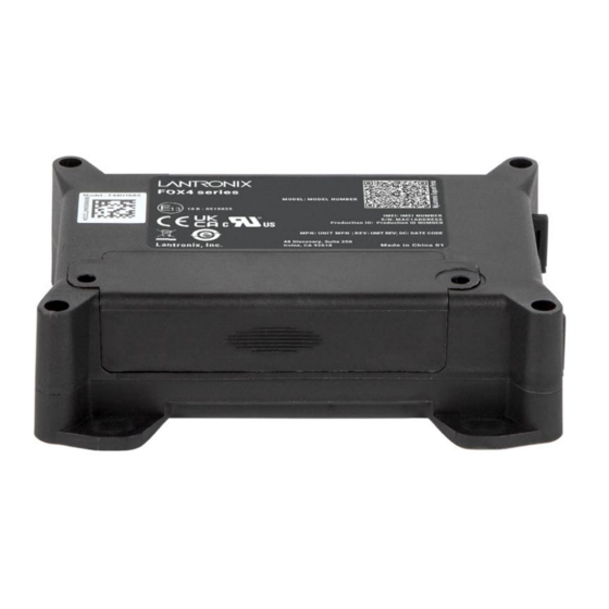
8: Housing Housing Figure 25: FOX4-4G housing FOX4 – 4G Hardware Manual... -
Page 41: Appendix
9: Appendix Appendix Schematics Figure 26 below illustrates a common schematic to install the FOX4-4G devices in the vehicle. For detailed information, refer to 1.7 Related Documents [5]. 9.1.1 Installation guidance Upon installing the FOX4-4G in a vehicle, you will be able to track and locate the vehicle all the time and you will be automatically notified when disagreements with your stored configuration in the FOX4-4G device occur. -
Page 42: Gprs Coding Scheme
9: Appendix running. To create an application with the FOX4-4G devices and to obtain maximum benefit from the FOX4-4G operating firmware, you have to setup a specific configuration and store it in the device. All PFAL commands can be sent to the FOX4-4G with the help of the Workbench software, which can be downloaded from our website. -
Page 43: Compliance
10: Compliance Compliance (According to ISO/IEC Guide and EN 45014) Manufacturer's Name & Address: Lantronix, Inc., 48 Discovery, Suite 250, Irvine, CA 92618 USA Declares that the following product: FOX4-4G Conforms to the following standards or other normative documents: Country... -
Page 44: Federal Communications Commission (Fcc) Compliance Statement
10: Compliance 10.1 Federal Communications Commission (FCC) Compliance Statement This device complies with part 15 of the FCC Rules. Operation is subject to the following two conditions: • This device may not cause harmful interference. This device must accept any interference received, including interference that may cause •... -
Page 45: Ised Rf Exposure Information
10: Compliance This Class B digital apparatus complies with Canadian ICES-003. Cet appareil numérique de la classe B est conforme à la norme NMB-003 du Canada. 10.4 ISED RF Exposure Information This device complies with ISED radiation exposure limits set forth for an uncontrolled environment. -
Page 46: Eu Declaration Of Conformity
10: Compliance 10.5 EU Declaration of Conformity Figure 27: EU Declaration of Conformity FOX4 – 4G Hardware Manual... -
Page 47: Eu Statements
ограничено само за вътрешна употреба. Може да не се работи наоткрито. Česky [Czech] Lantronix, Inc. tímto prohlašuje, že tento FOX4-4G device je ve shodě základními požadavky a dalšími příslušnými ustanoveními směrnice 2014/53/EU. Úplné znění ES prohlášení o shodě je k dispozici na této internetové... - Page 48 EU Notice of Restrictions on Use: This device is limited to indoor use only. It may not be operated outdoors. Español Por medio de la presente Lantronix, Inc. declara que el FOX4-4G device [Spanish] module cumple con los requisitos esenciales y cualesquiera otras disposiciones aplicables o exigibles de la Directiva 2014/53/EU.
- Page 49 Il ne doit pas être utilisé àl'extérieur Icelandic Hér með lýsir Lantronix, Inc. því yfir að FOX4-4G device sé í samræmi við grunnkröfur og önnur viðeigandi ákvæði tilskipunar 2014/53 / ESB. Í heildartexta ESB-samræmisyfirlýsingarinnar er að finna á eftirfarandi internetfangi: https://www.lantronix.com/products/fox-series/...
- Page 50 10: Compliance Code Language Statement Latviski [Latvian] Ar šo Lantronix, Inc. deklarē, ka FOX4-4G device atbilst Direktīvas 2014/ 53/EU būtiskajām prasībām un citiem ar to saistītajiem noteikumiem. Pilns ES atbilstības deklarācijas teksts ir pieejams šādā tīmekļa vietnē: https://www.lantronix.com/products/fox-series/ ES paziņojums par lietošanas ierobežojumiem: šo ierīci var izmantot tikai iekštelpās.
- Page 51 10: Compliance Code Language Statement Norwegian Lantronix, Inc. erklærer herved at denne FOX4-4G device er i samsvar med de grunnleggende kravene og andre relevante bestemmelser i direktiv 2014/53 / EU. Den fullstendige teksten til EU-samsvarserklæringen er tilgjengelig på følgende internettadresse: https://www.lantronix.com/products/fox-...
- Page 52 10: Compliance Code Language Statement Slovensko Lantronix, Inc. izjavlja, da je ta FOX4-4G device v skladu z bistvenimi [Slovenian] zahtevami in ostalimi relevantnimi določili direktive 2014/53/EU. Celotno besedilo izjave EU o skladnosti je na voljo na naslednjem spletnem naslovu: https://www.lantronix.com/products/fox-series/ Obvestilo EU o omejitvah uporabe: Ta naprava je omejena samo na notranjo uporabo.
-
Page 53: Declaration Of Conformity
10: Compliance 10.7 UK Declaration of Conformity Figure 28: UK Declaration of Conformity FOX4 – 4G Hardware Manual...
Need help?
Do you have a question about the FOX4 Series and is the answer not in the manual?
Questions and answers