
Related Manuals for Lantronix FOX4 Series


Summary of Contents for Lantronix FOX4 Series
- Page 1 FOX4 Series Promotion Kit User Guide FOX4-4G Part Number PMD-00244 Revision A April 2024...
- Page 2 Intellectual Property © 2024 Lantronix, Inc. All rights reserved. No part of the contents of this publication may be transmitted or reproduced in any form or by any means without the written permission of Lantronix. Lantronix is a registered trademark of Lantronix, Inc. in the United States and other countries.
- Page 3 Distribution (BSD) license, the GNU General Public License (GPL) as published by the Free Software Foundation (FSF), or the Python Software Foundation (PSF) License Agreement for Python 2.7.3 (Python License). Lantronix grants you no right to receive source code to the Open Source software; however, in some cases, rights and access to source code for certain Open Source software may be available directly from Lantronix’...
- Page 4 Revision History Date Rev. Comments Initial Version April 2024 For the latest revision of this product document, please check our online documentation at www.lantronix.com/support/documentation. FOX4 Series Promotion Kit User Guide...
-
Page 5: Table Of Contents
Connecting FOX4-4G device to the Telematic Eval Kit ........11 3.1.3 Charge the internal battery and power up the device ........11 3.1.4 Installing and configuring Lantronix Workbench software ......13 Technical Support ....................15 Percepxion ......................15 Telematic Eval Kit - Hardware Description ........16 Front panel overview ..................... -
Page 6: About This Document
It also explains how to operate the device with your own SIM card and how to connect to and add the FOX4-4G device to your own remote management server. Version: FOX4 Series Promotion Kit User Guide... -
Page 7: Overview
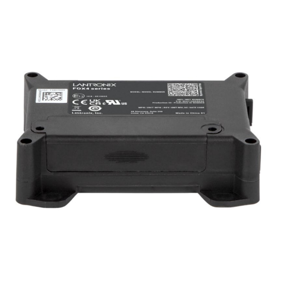
CAN-Bus interface and programmable inputs and outputs for almost every application within the automobile industry. For more details, please refer to the chapter 3.1, and download the document FOX4 Series Hardware Manual from our website. Figure 1: Promotion Kit Delivery Package... - Page 8 SIM-Card Percepxion for evaluation purposes. Instruction sheet Necessary information on how to get started with Lantronix AVL devices. Telematic Eval Kit (BOX) Telematic Eval Kit Allows you to connect the FOX4-4G device to your PC for testing and evaluation purposes.
-
Page 9: Related Documents
15 V including UK/US/AU/EU adapters Table 1: The list of items included in the PROMOTION-KIT. Related documents The FOX Series documentation includes user guides, quick start installation guides, and application notes. They are available from the Lantronix website. User documents: lantronix.com/products/fox-series/ Application notes: lantronix.com/resources/application-notes/... - Page 10 WLAN to your platform server. Table 3: Application Notes These PDF files are viewable and printable from Adobe Reader. If you do not have the Adobe Reader installed, you can download it from http://www.adobe.com FOX4 Series Promotion Kit User Guide...
-
Page 11: Getting Started
2. Connect the FOX4-4G unit to the Telematic Eval Kit, PC, and apply power. 3. Charge the internal battery of the FOX4-4G and power up the device. 4. Install the Lantronix Workbench software and start the evaluation of the FOX4-4G device 5. -
Page 12: Connecting Fox4-4G Device To The Telematic Eval Kit
1. After connecting the AC adapter to the Telematic Eval Kit and into the wall socket, apply power to the Telematic Eval Kit and FOX4-4G device by turning just the +IN switch to ON position. FOX4 Series Promotion Kit User Guide... - Page 13 Figure 7: Overview of the Telematic Eval Kit top panel (IGN = ON) +IN - It supplies power to the Telematic Eval Kit and FOX4-4G device IGN - It turns on the FOX4-4G device (wakes it up from the IGN sleep mode) FOX4 Series Promotion Kit User Guide...
-
Page 14: Installing And Configuring Lantronix Workbench Software
Go to lantronix.com/products/workbench/ x64 zip file. Extract the contents of the zip file to display lantronix-workbench-win-x64 folder. Go to lantronix-workbench-win-x64 > bin folder. In the bin folder, double-click the workbench_win_x64 file to start Workbench. The Load profile dialog box displays with Default profile selected. Click OK. - Page 15 HTML format. Click Terminal to open a new Terminal, Terminal 1 displays. Click Terminal 1 and go to Connection View. Right-click the Connection View window to enlarge it and FOX4 Series Promotion Kit User Guide...
-
Page 16: Technical Support
To view the support options, go to lantronix.com/technical-support/. Percepxion Percepxion is a cloud or on-premise portal for the centralized management of Lantronix devices. A browser based interface (including mobile phone app support) that allows an administrator to view status, logs and charts, update firmware and configuration, view and edit telemetry, execute PFAL commands, and monitor Lantronix devices. -
Page 17: Telematic Eval Kit - Hardware Description
IO - switches These pins have dual functions. All are controlled by the internal firmware of FOX4-4G. Therefore, the user must define whether to use them as analog or digital pins. The FOX4 Series Promotion Kit User Guide... - Page 18 Switch the IO/1-Switch to the "Digital OUT / analogue IN" position Send the command "$PFAL,IO4.Set=high" to set it to High Send the command "$PFAL,IO5.Set=low" to set it to Low Table 5: Top panel components and their functionality FOX4 Series Promotion Kit User Guide...
-
Page 19: Rear Panel Overview
A description of each of the items on the rear panel is provided in Table 6. Item Description Serial port 0 Via your own RS-232 cable you can connect the PROMOTION-KIT to a PC and evaluate the connected FOX4-4G device. Table 6: Rear panel components FOX4 Series Promotion Kit User Guide... -
Page 20: Explanation Of Sample Configuration
Green LED – To indicate TCP/MQTT/REST/Percepxion Connection Status $PFAL,CNF.Set,ALIAS.IO11=_LEDG Yellow LED - To indicate GNSS Fix Status $PFAL,CNF.Set,ALIAS.IO12=_LEDY Red LED - To indicate Power Supply Status $PFAL,CNF.Set,ALIAS.IO13=_LEDR Power Modes Setup all needed Device Power Modes. $PFAL,CNF.Set,DEVICE.IGNTIMEOUT=60000 FOX4 Series Promotion Kit User Guide... - Page 21 Description and Configuration Battery Modes Setup all needed Device Battery Modes. $PFAL,CNF.Set,DEVICE.BAT.MODE=auto,3.50 $PFAL,Sys.Bat.chargemode=eco $PFAL,Sys.Bat.mode=auto GNSS Setup GNSS $PFAL,GPS.NAV.GNSS=GPS,GALILEO,GLONASS,BEIDOU Lantronix SIM Card Setup the Cellular connection for LANTRONIX SIM card. $PFAL,CNF.Set,GPRS.APN=data641003 $PFAL,CNF.Set,PPP.USERNAME $PFAL,CNF.Set,PPP.PASSWORD $PFAL,Cnf.Set,GSM.OPERATOR.SELECTION=auto $PFAL,CNF.Set,GSM.OPERATOR.BLACKLIST $PFAL,CNF.Set,GPRS.AUTOSTART=1 Buffer Data Nonvolatile buffered data. $PFAL,CNF.Set,TCP.CLIENT.SENDMODE=2 Percepxion Setup Percepxion Connection.
- Page 22 Set Red LED to on when good ext. Power. $PFAL,CNF.Set,AL10=Sys.Power.sVoltage>9:IO_LEDR.set=Hi Set Green LED off when no Cellular Network. $PFAL,CNF.Set,AL11=GSM.eOplost:IO_LEDG.set=low Set Green LED fast blinking when Cellular network attached. $PFAL,CNF.Set,AL12=GSM.eOpfound:IO_LEDG.set=cyclic,200 ,200 Set Green LED slower blinking when GPRS attached. $PFAL,CNF.Set,AL13=GSM.GPRS.eConnected:IO_LEDG.Set=cyc lic,400,400 FOX4 Series Promotion Kit User Guide...
- Page 23 Check position every 20 seconds if the distance is > 200m, set Data Point to CF. $PFAL,CNF.Set,AL17=SYS.TIMER.e_20SEC&GPS.Nav.Position. s0>200&GPS.Nav.sSpeed>2:GPS.Nav.Position0=current Check position Heading changes more than 15° after last position sent and speed higher than 2m/s to prevent non moving data. $PFAL,CNF.Set,DEVICE.GPS.HEADING=15 $PFAL,CNF.Set,AL18=GPS.Nav.eChangeHeading&GPS.Nav.sSpe ed>2:GPS.Nav.Position0=current FOX4 Series Promotion Kit User Guide...
-
Page 24: Appendix
Activation of outputs in a number of ways (activate a buzzer) • Data logging activation (stores the data inside the device) • Handling of incoming messages of any type (Activation on SMS text type • Vehicle doors Lock & Unlock • FOX4 Series Promotion Kit User Guide... -
Page 25: Installation And Service Cables
RS-232 interface via the 4-pin UCOM connector. This cable has an 8pin double row connector that connects to the FOX4-4G device and a 4pin double row connector that connects to one of the LANTRONIX accessories or 3 party products. - Page 26 = + 2.8 .. +5.0 V temperature and humidity sensors. BROWN Ground Reference. PURPLE RxA_1 Input Serial Port 1 - Receive data. V24, ±12 V BLACK TxA_1 Output Serial Port 1- Transmit data V24, ±12 V FOX4 Series Promotion Kit User Guide...
- Page 27 Table 9: Pinout of accessory port cable with 2x3pin connector to DB9 serial female socket The pinout of the cable 60286 (OBDII 4Pin Cable) is listed in table below: 2x4 MICROFIT OBDII connector Description CAN_High CAN_Low IGN as separate wire Table 10: Pinout of the cable 60286 FOX4 Series Promotion Kit User Guide...
-
Page 28: Installing Your Own Sim Card And Replacing The Internal Battery
SIM card and powering up the device, send the following commands from Workbench Editor ❽ (see Figure 10) to the FOX4-4G device. $PFAL,Cnf.Set,GPRS.APN=data641003 (The APN used here belongs to Lantronix Connectivity Services. Your network operator provides the APN) $PFAL,Cnf.Set,GPRS.QOS=3,4,3,0,0 $PFAL,Cnf.Set,GPRS.QOSMIN=0,0,0,0,0 SETUP $PFAL,Cnf.Set,PPP.USERNAME=gprs (If your provider requires, Lantronix Connectivity... - Page 29 Documents [1]. $<MSG.Info.ServerLogin> $DeviceName=FOX4 $Security=0 $Software=avl_2.13.0 (BxBGT1gzIHJldjowMy1OVUNIAgEA) FOX4-4G $Hardware=FOX4 rev:03-NUCH LOGIN DATA TO YOUR $LastValidPosition=$GPRMC,143445.000,A,5040.4096,N,01058.8542,E,0.01,0.00,0403 SERVER 15,, $IMEI=353816054739497 $PhoneNumber=+491734567124564 $LocalIP=10.208.151.168 $CmdVersion=2 $SUCCESS $<end> Table 12: ServerLogin data sent from FOX4 device to remote server FOX4 Series Promotion Kit User Guide...
Need help?
Do you have a question about the FOX4 Series and is the answer not in the manual?
Questions and answers