Oracle Sun Server X4-4 Service Manual
Hide thumbs
Also See for Sun Server X4-4:
- Installation manual (148 pages) ,
- Installation manual (38 pages)
Table of Contents
Advertisement
Quick Links
Download this manual
See also:
Installation Manual
Advertisement
Chapters
Table of Contents
Troubleshooting

Subscribe to Our Youtube Channel
Related Manuals for Oracle Sun Server X4-4


Summary of Contents for Oracle Sun Server X4-4
- Page 1 Sun Server X4-4 Service Manual Part No: E38221-05 October 2015...
- Page 3 Oracle. Oracle Corporation and its affiliates will not be responsible for any loss, costs, or damages incurred due to your access to or use of third-party content, products, or services, except as set forth in an applicable agreement between you and Oracle.
- Page 4 Oracle Corporation et ses affiliés déclinent toute responsabilité ou garantie expresse quant aux contenus, produits ou services émanant de tiers, sauf mention contraire stipulée dans un contrat entre vous et Oracle. En aucun cas, Oracle Corporation et ses affiliés ne sauraient être tenus pour responsables des pertes subies, des coûts occasionnés ou des dommages causés par l’accès à...
-
Page 5: Table Of Contents
Contents Using This Documentation ................ 11 Sun Server X4-4 Service Manual Overview ............ 15 Sun Server X4-4 Overview ................ 17 Server Overview ................... 18 Supported Components ................ 18 External Components and Features .............. 19 Server Front Panel Features .............. 19 Server Back Panel Features .............. 20 Server Subsystems Overview ................ 21 System Block Diagrams ................. - Page 6 ▼ Power Off, Graceful (Power Button) ............ 97 ▼ Power Off, Immediate (Power Button) .......... 98 Front Panel Power Off Options .............. 99 ▼ Power Off, Remote (Oracle ILOM CLI) .......... 100 ▼ Power Off, Remote (Oracle ILOM Web Interface) ........ 101 Sun Server X4-4 Service Manual • October 2015...
-
Page 7: Fault Remind Button
Managing the Locator Indicator .............. 104 ▼ Turn On the Locator Indicator Remotely (Oracle ILOM CLI) .... 105 ▼ Turn On the Locator Indicator Remotely (Oracle ILOM Web Interface) .. 106 ▼ Manage the Locator Indicator Locally .......... 106 ▼ Remove the Server Cover ................ 107 Servicing CRU Components ................ - Page 8 PEI Error Codes .................. 273 S3 Resume Progress Codes .............. 274 S3 Resume Error Codes ................ 274 Recovery Progress Codes .............. 274 Recovery Error Codes ................ 275 PEI Beep Codes .................. 275 DXE Phase DXE Status Codes .............. 275 Sun Server X4-4 Service Manual • October 2015...
- Page 9 Contents DXE Error Codes ................ 278 DXE Beep Codes ................ 278 ACPI/ASL Checkpoints ................ 278 OEM-Reserved Checkpoint Ranges ............ 279 Post Codes From hostdiags .............. 279 Server Specifications .................. 281 Server Specifications .................. 281 Physical Specifications ................. 281 Electrical Specifications ................ 282 Environmental Requirements .............. 282 Index ........................ 285...
- Page 10 Sun Server X4-4 Service Manual • October 2015...
-
Page 11: Using This Documentation
You can obtain the latest version in one of following ways: Oracle System Assistant – This is a factory-installed option for Sun Oracle x86 servers. It ■ has all the tools and drivers you need and resides on an internal USB flash stick. -
Page 12: Documentation And Feedback
These web sites provide additional resources: Support: ■ https://support.oracle.com ■ Training: http://education.oracle.com Contributors Primary Authors: Ralph Woodley, Ray Angelo, Cynthia Chin-Lee, Mark McGothigan, Michael Bechler, Lisa Kuder. Contributors: Kenny Tung, Barry Wright, David Savard Sun Server X4-4 Service Manual • October 2015... -
Page 13: Change History
Server X4-4 Installation Guide for Linux Operating System information to add support for the Oracle Linux Fault Management Architecture software available with Oracle Hardware Management Pack 2.3. Minor editorial updates to Sun Server X4-4 Installation Guide for Windows Operating System. - Page 14 Sun Server X4-4 Service Manual • October 2015...
-
Page 15: Sun Server X4-4 Service Manual Overview
Sun Server X4-4 Service Manual Overview This document contains service, maintenance, and component replacement procedures and information for the Oracle® Sun Server X4-4. The following table describes the major sections of this manual. Description Link Server system overview. “Sun Server X4-4 Overview”... - Page 16 Sun Server X4-4 Service Manual • October 2015...
-
Page 17: Sun Server X4-4 Overview
Sun Server X4-4 Overview This section describes the major features, components, and capabilities of the Oracle Sun Server X4-4. Description Link Server overview statement “Server Overview” on page 18 Components and features of the “External Components and Features” on page 19... -
Page 18: Server Overview
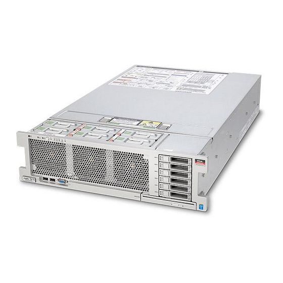
Server Overview Server Overview The Sun Server X4-4 is a 3RU tall rack-mount server system that features two or four Intel Xeon E4890 Series 15-core 2.8 GHz CPUs. The system memory is contained on memory riser (MR) cards, each with the capacity for up to 12 low-voltage DDR3 DIMMs. The server can support up to eight MR cards (four-CPU system). -
Page 19: External Components And Features
■ Oracle Integrated Lights Out Manager (ILOM) on the Service Processor. ■ Oracle System Assistant (OSA) on an optional internal USB flash drive. ■ Oracle Hardware Management Pack. ■ Oracle Enterprise Management Ops Center, which can be downloaded from the Oracle site. External Components and Features The following sections call out the features of the server front and back panels. -
Page 20: Server Back Panel Features
DB-15 video connector SATA DVD drive (optional) 12–17 Storage drive slots 0–5 (from bottom to top) Server Back Panel Features The following illustration shows the server back panel and describes its features. Sun Server X4-4 Service Manual • October 2015... -
Page 21: Server Subsystems Overview
“System Block Diagrams” on page 22 ■ “Processor Subsystem” on page 23 ■ “Memory Subsystem” on page 26 ■ “Cooling Subsystem” on page 26 ■ “Input/Output (I/O) Subsystem” on page 29 ■ “System Management Subsystem” on page 31 ■ Sun Server X4-4 Overview... -
Page 22: System Block Diagrams
Server Subsystems Overview System Block Diagrams The Sun Server X4-4 can be configured with four CPUs or two CPUs. This section shows the system block diagrams for these two server configurations: “Four-CPU Block Diagram” on page 22 ■ “Two-CPU Block Diagram” on page 23 ■... -
Page 23: Processor Subsystem
Server Subsystems Overview Two-CPU Block Diagram Processor Subsystem The Sun Server X4-4 uses the Intel Xeon E7-8895 v2 15-core 2.8 GHz processor and supports two CPU-based configurations: a two-CPU configuration and a four-CPU configuration. Sun Server X4-4 Overview... - Page 24 Call Out Description Air baffle CPU P1 CPU P0 Memory riser card P1/MR1 Memory riser card P1/MR0 Memory riser card P0/MR1 Memory riser card P0/MR0 Sun Server X4-4 Service Manual • October 2015...
- Page 25 Memory riser card P0/MR1 Memory riser card P3/MR0 Memory riser card P0/MR0 Memory riser card P2/MR1 CPU P3 Memory riser card P2/MR0 CPU P2 Memory riser card P1/MR1 CPU P1 Memory riser card P1/MR0 CPU P0 Sun Server X4-4 Overview...
-
Page 26: Memory Subsystem
“Memory Riser Card and DIMM Reference” on page 141 Cooling Subsystem The internal components in the Sun Server X4-4 are cooled by air that is pulled in through the front of the server and exhausted out the back of the server. Cooling occurs in two areas of the chassis, the power supply area and the motherboard area. - Page 27 However, if in the rare case that both fans in a pair fail, Oracle ILOM will power off the system to prevent thermal damage.
- Page 28 Temperature sensor TS_PS (U4603) Temperature sensor TS_ZONE1 (U4507) Temperature sensor TS_ZONE2 (U4505) Temperature sensor TS_OUT (U4506) Temperature sensor TS_TVL_1 (U4002) Temperature sensor TS_TVL_0 (U4302) Temperature sensor TS_ZONE0_B (U4509) Temperature sensor TS_ZONE0_A (U4508) Sun Server X4-4 Service Manual • October 2015...
-
Page 29: Power Subsystem
Input/Output (I/O) Subsystem The server I/O storage subsystem consists of the following: “11 PCIe Gen 3 Slots” on page 30 ■ “Six 2.5-inch Drive Bays” on page 30 ■ “ SATA DVD +/-RW Drive” on page 30 ■ Sun Server X4-4 Overview... - Page 30 The two internal USB ports are located on the motherboard between the disk drive backplane and the PSU backplane boards. The ports can take a standard USB flash device, which can be Sun Server X4-4 Service Manual • October 2015...
-
Page 31: System Management Subsystem
Assistant USB device. Do not use the Oracle System Assistant USB drive for booting an OS or as server storage. If installed in your server, the Oracle System Assistant USB drive must be installed in the internal port labeled "OSA USB" and it must contain only the Oracle System Assistant file system. - Page 32 Protocol (SNMP). You can use this information to integrate your Oracle servers into your data center management infrastructure. Set up an Oracle ILOM trap proxy that forwards SNMP traps from your Oracle ILOM ■ service processor to the host OS.
-
Page 33: Troubleshooting And Diagnostics
Information about attaching devices to the “Back Panel Pinhole Switches” on page 61 server to perform troubleshooting. Information about contacting Oracle support. “Getting Help” on page 62 Troubleshooting Server Component Hardware Faults This section contains maintenance-related information and procedures that you can use to troubleshoot and repair server hardware issues. -
Page 34: Troubleshooting Server Hardware Faults
3. Prepare the server for service using Oracle ILOM. If the hardware fault requires service (physical access to the server), use Oracle ILOM to power off the server, activate the Locate LED, and take the server offline. - Page 35 Troubleshoot Hardware Faults Depending on the component, you might need to clear the fault in Oracle ILOM. Generally, components that have a FRU ID clear the fault automatically. Related Information: “Troubleshoot Hardware Faults” on page 35 ■ Troubleshoot Hardware Faults The screens shown in this procedure might differ from those for your server.
- Page 36 In the above example, the Status screen shows that the Memory subsystem requires service. This indicates that a hardware component within the subsystem is in a fault state. To identify the component, click on the subsystem name. Sun Server X4-4 Service Manual • October 2015...
- Page 37 Troubleshoot Hardware Faults The subsystem screen appears. The above example shows the Memory subsystem screen and indicates that DIMM 8 on CPU 0 has an uncorrectable ECC fault. To get more information, click one of the Open Problems links. The Open Problems screen provides detailed information, such as the time the event occurred, the component and subsystem name, and a description of the issue.
-
Page 38: Troubleshooting And Diagnostic Information
Troubleshoot Hardware Faults After servicing the component, you might need to clear the fault in Oracle ILOM. For Note - more information, refer the component service procedure. Troubleshooting and Diagnostic Information The following table lists diagnostic and troubleshooting procedures and references that can help you resolve server issues. - Page 39 (no blink). Locator Indicator On When the Locator indicator is activated from Oracle ILOM or from the front panel (by pressing the Locate button), the indicator blinks at the fast blink rate. The indicator assists in finding a server within a rack of servers (for example, when activated remotely to correctly identify a server requiring service).
- Page 40 For a server with one of its PSU's in a failed state, the amber Service Action Required and PS REAR indicators are on steady. The green system OK indicator and the green SP indicator are on steady. Sun Server X4-4 Service Manual • October 2015...
-
Page 41: Memory Failure
Troubleshoot Hardware Faults For indicator blink rate information, see “Indicator Blink Rates” on page Memory Failure For a server with a failure in the memory subsystem, the amber Service Action Required and MEM TOP indicators are on steady. The green system OK indicator and the green SP indicator are on steady. - Page 42 “Indicator Blink Rates” on page SP Failure For a server with an SP fault, the amber Service Action Required indicator is on steady. The green system OK indicator and the green SP indicator are off. Sun Server X4-4 Service Manual • October 2015...
-
Page 43: Indicator Blink Rates
Troubleshoot Hardware Faults For indicator blink rate information, see “Indicator Blink Rates” on page Front Panel Lamp Test To perform a lamp test of all front panel indicators, press the Locate button three times within a five second period. All the indicators light up and remain on steady for 15 seconds (see “Unison Steady On”... - Page 44 For the steady off state, an indicator is continually off (not lit) and does not blink. This indicates that a system is not operational, for example, no AC power (unlit green system OK indicator) or a subsystem not in a fault state (unlit amber Service Action Required indicator). Sun Server X4-4 Service Manual • October 2015...
- Page 45 Troubleshoot Hardware Faults Slow Blink Rate For the slow blink rate, the indicator (typically green) repeatedly lights for half a second during a one second interval (1 Hz) and turns off for half a second. The slow blink rate indicates an on- going activity.
- Page 46 (1 Hz). Typically, this is limited to three successive blinks. This confirms the successful insertion of a removable device (for example, a storage drive or blade) into a powered system (confirming the power connection). Sun Server X4-4 Service Manual • October 2015...
- Page 47 Troubleshoot Hardware Faults Insertion Blink The insertion blink is three successive blinks of a hot-swap component's primary status indicator (for example, the green system OK indicator). The insertion blink occurs immediately after three successive unison blinks (see “Slow Unison Blink Rate” on page 46) of all the component indicators.
- Page 48 A repeating sequence in which each indicator successively lights for 0.5 sec each to indicate that diagnostics are running. This blink rate is used only on systems or components capable of running diagnostics (for example, blade servers). Sun Server X4-4 Service Manual • October 2015...
-
Page 49: The Server Fault Remind Test Circuits
Troubleshoot Hardware Faults The Server Fault Remind Test Circuits The sever has two internal test circuits, the System Fault Remind Circuit and the DIMM Fault Remind Circuit. The circuits help you locate failed components. For example, use the System Fault Remind Circuit to locate a failed CPU or memory riser card, and use the DIMM Fault Remind Circuit to locate a failed DIMM. - Page 50 Prevention: When servicing the server, ensure that the divider and baffle are installed correctly and that the server has no unoccupied external-facing slots. Never operate the server without the top cover installed. Sun Server X4-4 Service Manual • October 2015...
-
Page 51: Troubleshooting Power Issues
Troubleshoot Hardware Faults Hardware Component Failure Components, such as power supplies and fan modules, are an integral part of the server cooling system. When one of these components fails, the server internal temperature can rise. This rise in temperature can cause other components to enter into an over temperature state. Additionally, some components, such as processors, might overheat when they are failing, which can also generate an over-temperature event. -
Page 52: Ac Power Connection
Prevention: Use the AC power cord retaining clips and position the cords to minimize the risk of accidental disconnection. Ensure that the AC circuits that supply power to the server are stable and not overburdened. Sun Server X4-4 Service Manual • October 2015... - Page 53 Troubleshoot Hardware Faults Power Supplies (PSUs) The server power supplies (PSUs) provide the necessary server voltages from the AC power outlets. If the PSUs are inoperable, unplugged, or disengaged from the internal connectors, the server cannot power on. Action: Check that the AC cables are connected to both PSUs and that the PSUs are operational (the PSU indicator panel should have a lit green AC OK indicator).
-
Page 54: Troubleshooting With Diagnostic Tools
The server and its accompanying software and firmware contain diagnostic tools and features that can help you isolate component problems, monitor the status of a functioning system, and exercise one or more subsystems to disclose more subtle or intermittent hardware-related problems. Sun Server X4-4 Service Manual • October 2015... -
Page 55: Diagnostic Tools
Diagnostic Tools The selection of diagnostic tools available for your server range in complexity from a comprehensive validation test suite (Oracle VTS) to a chronological event log (Oracle ILOM System Log). The selection of diagnostic tools also include standalone software packages, firmware-based tests, and hardware-based LED indicators. -
Page 56: Diagnostic Tool Documentation
The following sections contain procedural information for attaching devices to the server: so you can access diagnostic tools when troubleshooting and servicing the server: “Attach Devices to the Server” on page 57 ■ “Back Panel Connector Locations” on page 58 ■ Sun Server X4-4 Service Manual • October 2015... -
Page 57: Attach Devices To The Server
Connect an Ethernet cable to the Gigabit Ethernet (NET) connectors. See “Back Panel Connector Locations” on page To connect to the service processor's Oracle ILOM over the network, connect an Ethernet cable to the Ethernet port labeled NET MGT. See “Back Panel Connector Locations”... -
Page 58: Back Panel Connector Locations
By default, the service processor (SP) console (NET MGT) port sends serial port output from the server. Using Oracle ILOM, you can specify that the host console (COM1) be assigned as owner of the server serial port output. This feature is useful for Windows kernel debugging, as it enables you to view non-ASCII character traffic from the host console. - Page 59 Oracle Integrated Lights Out Manager (ILOM) 3.2 Documentation Library at: http://www. oracle.com/goto/ILOM/docs. Open an SSH session and at the command line log in to the SP Oracle ILOM CLI. Log in as a user with root or administrator privileges. For example: ipadress ssh root@ where ipadress is the IP address of the server SP.
-
Page 60: Ethernet Port Boot Order And Device Naming
Assign Serial Port Output Using the Web Interface Log in to the service processor Oracle ILOM web interface. To log in, open a web browser and direct it using the IP address of the server SP. Log in as root or a user with administrator privileges. -
Page 61: Back Panel Pinhole Switches
Assign Serial Port Output Using the Web Interface Ethernet Port Boot Order The order in which the BIOS detects the Ethernet ports during server boot is listed below. 1. NET 0 2. NET 1 3. NET 2 4. NET 3 You can change the boot priority using the Boot Device Priority screen available in the Note - Boot menu of the BIOS Setup Utility. -
Page 62: Getting Help
If the troubleshooting procedures in this chapter fail to solve your problem, use the following table to collect information that you might need to communicate to support personnel. System Configuration Your Information Information Needed Service contract number System model Operating environment System serial number Sun Server X4-4 Service Manual • October 2015... -
Page 63: Locating The Chassis Serial Number
■ From the Oracle ILOM command-line interface (CLI), type the command: show/SYS. ■ From the Oracle ILOM web interface, view the serial number in the System Information ■ tab. From Oracle System Assistant, view the serial number in the System Overview (home ■... - Page 64 Sun Server X4-4 Service Manual • October 2015...
-
Page 65: Servicing The Server
Procedural information about “Clear Hardware Fault Messages” on page 85 clearing hardware faults in Oracle ILOM. Component Serviceability, Locations, and Designations This section contains information about component service designations, serviceability, and locations. “Component Serviceability” on page 66 ■... -
Page 66: Component Serviceability
The replaceable components in your server are designated as either a customer-replaceable unit (CRU) or a field-replaceable unit (FRU). A part designated as a FRU must be replaced by an Oracle-qualified service technician. A part designated as a CRU can be replaced by a person who is not an Oracle-qualified service technician. - Page 67 Component Serviceability, Locations, and Designations Replaceable Components Call Out Description Call Out Description Motherboard Storage drive backplane board SP card Heatsinks and CPUs (2 or 4) HBA card Memory riser cards (4 or 8) System battery (CR 2032) Fan modules Power supplies Fan board HBA cable...
- Page 68 Call Out Description Power supplies Air baffle (2-CPU configuration only) Power supply backplane board Motherboard SP card Storage drive HBA/PCIe cards DVD drive Fan module Heatsink Fan board Cover Storage drive backplane board Sun Server X4-4 Service Manual • October 2015...
-
Page 69: Component Designations
Component Serviceability, Locations, and Designations Call Out Description Call Out Description Memory riser card Server chassis Component Designations This section shows the slot naming designations for internal and external slots: “Fan Module Slot Designations” on page 69 ■ “CPUs and Memory Riser Card Slots Designations” on page 70 ■... - Page 70 P0/MR0 and P0/MR1. Slots 2 and 3 are paired with CPU socket, P1 and are designated as P1/MR0 and P1/MR1. This numbering pattern continues for the remaining slots. Call Out Description Call Out Description MR card slot 0, P0/MR0 MR card slot 6, P3/MR0 Sun Server X4-4 Service Manual • October 2015...
- Page 71 Component Serviceability, Locations, and Designations Call Out Description Call Out Description MR card slot 1, P0/MR1 MR card slot 7, P3/MR1 MR card slot 2, P1/MR0 CPU-3 (P3) MR card slot 3, P1/MR1 CPU-2 (P2) MR card slot 4, P2/MR0 CPU-1 (P1) MR card slot 5, P2/MR1 CPU-0 (P0)
- Page 72 SP card. The slots are designated from right to left. The six slots on the right side are designated as PCI-1 to PCI-6. The five slots on the left are designated as PCI-7 to PCI-11. Sun Server X4-4 Service Manual • October 2015...
- Page 73 The bottommost slot is designated as HDD-0, and the topmost slot is HDD- The two internal USB slots are located between the disk backplane board and the power supply backplane board. The front slot is used for the optional Oracle System Assistant USB stick and is marked "OSA USB".
-
Page 74: Performing Electrostatic Discharge And Static Prevention Measures
HDD2 USB port HDD1 Performing Electrostatic Discharge and Static Prevention Measures Electrostatic discharge (ESD) sensitive devices, such as the PCIe cards, hard drives, CPUs, and memory cards, require special handling. Sun Server X4-4 Service Manual • October 2015... -
Page 75: Using An Anti-Static Wrist Strap
DIMMs, and CPUs. You can use the following items as anti-static mats: Anti-static bag used to wrap a replacement part ■ ESD mat (orderable from Oracle) ■ A disposable ESD mat (shipped with some optional system components) ■... -
Page 76: Tools And Equipment
The following illustration shows the storage drives and storage drive filler panels installed in the server. Sun Server X4-4 Service Manual • October 2015... -
Page 77: Locating A Failed Memory Riser Card, Dimm, Or Cpu
Locating a Failed Memory Riser Card, DIMM, or CPU Legend Storage drive filler panels Storage drives Locating a Failed Memory Riser Card, DIMM, or CPU The following sections provide information about using the system and DIMM Fault Remind test circuits: “System Fault Remind Circuit Components”... -
Page 78: Memory Riser Card And Cpu Fault Indicators
Locating a Failed Memory Riser Card, DIMM, or CPU Memory Riser Card and CPU Fault Indicators The memory riser card Fault indicator LEDs are visible through the small hole on top of the card. Sun Server X4-4 Service Manual • October 2015... -
Page 79: Cpu Fault Indicators
Locating a Failed Memory Riser Card, DIMM, or CPU Figure Legend Description Memory riser card Fault indicators CPU Fault Indicators The CPU Fault indicator LEDs are located on the motherboard between the memory riser cards and the CPU. To see a lit CPU Fault indicators, look down from the top of the server and sight through the memory riser cards and the support bracket near the CPU. -
Page 80: Dimm Fault Remind Circuit Components
Button and Charge Status Indicator are located near the right-side bank of DIMM slots at the front edge of the card. The DIMM Fault indicators are located next to the DIMM slots. Sun Server X4-4 Service Manual • October 2015... -
Page 81: Locate A Failed Memory Riser Card, Dimm, Or Cpu
Locate a Failed Memory Riser Card, DIMM, or CPU Legend Description Legend Description MR card Fault indicator Fault Remind button † DIMM Fault indicators Charge Status indicator † The indicator lights when the circuit is charged. Locate a Failed Memory Riser Card, DIMM, or CPU To locate a failed memory riser card, DIMM or CPU, use the fault remind circuits inside the server. - Page 82 DIMM Fault Remind circuit. To locate a failed CPU, look for the lit MR card Fault indicators and ■ the lit CPU Fault indicator. For more information, see “CPU Fault Indicators” on page Sun Server X4-4 Service Manual • October 2015...
- Page 83 Locate a Failed Memory Riser Card, DIMM, or CPU When a CPU is in a fault state, the Fault indicators for the CPU and both MR cards associated with the CPU light when the system Fault Remind button is pressed. The following illustration shows the lit indicators for a failed CPU, P0.
- Page 84 When a DIMM is in a fault state, the Fault indicator for the MR card containing the DIMM lights when the system Fault Remind button is pressed. The following illustration shows a Sun Server X4-4 Service Manual • October 2015...
-
Page 85: Clear Hardware Fault Messages
■ Clear Hardware Fault Messages After servicing a component, you might need to manually clear the fault using Oracle ILOM. Faults are captured by Oracle ILOM's fault manager and stored in the fault management database. If a component fault needs to be manually cleared, use the fmadm command from the Oracle ILOM Fault Management shell. - Page 86 Clear Hardware Fault Messages in to the Oracle ILOM CLI. For events logged in the Oracle ILOM event log, use the Oracle ILOM web interface. For information about using fmadm, refer to the Oracle ILOM User Guide at http://www. oracle.com/goto/ILOM/docs This procedure requires the use of the Oracle ILOM CLI interface.
- Page 87 ■ -u uuid – Show fault diagnosis events that match a specific universal unique identifier ■ (uuid). For command specifics, see the Oracle ILOM User Guide at: http://docs.oracle.com/cd/ E37444_01/index.html Use fmadm to clear the fault. Clear the fault according to whether you want to use the acquit, repair, replaced, or repaired.
- Page 88 Sun Server X4-4 Service Manual • October 2015...
-
Page 89: Preparing To Service The Server
This procedure uses the Oracle ILOM web interface. However, the procedure can be Note - performed using the Oracle ILOM CLI interface. For more information, refer to the Oracle ILOM documentation. A hot-service component can be serviced while the server is operating at full-power mode. For more information about component serviceability, see “Component Serviceability”... -
Page 90: Prepare The Server For Cold Service
This procedure uses a combination of the Oracle ILOM web and CLI interfaces. Note - However, the procedure can also be performed using only the Oracle ILOM CLI interface. For more information about the Oracle ILOM CLI interface, refer to the Oracle ILOM documentation. - Page 91 To power down the server and activate the front panel Locator indicator, do the following: Log in to the Oracle ILOM web interface. a. Type the server SP IP address into a web browser and log in as a user with root or administrator privileges.
- Page 92 However, ensure that the cables do not impede with, or are damaged by, the sliding movement. If necessary, label and remove cables from the back of the server. Sun Server X4-4 Service Manual • October 2015...
- Page 93 Prepare the Server for Cold Service b. (Optional) To move the CMA for access to the back of the server, see “Release the CMA” on page c. At the front of the server, release the slide rails by pushing the two green latches inward.
-
Page 94: Release The Cma
If you are using a cable management arm (CMA), you might need additional access to the back of the server. To gain additional access to the back of the server, release and reposition the CMA. Sun Server X4-4 Service Manual • October 2015... -
Page 95: (Optional) Remove The Server From The Rack
(Optional) Remove the Server from the Rack Press and hold the tab. Swing the CMA away from the server. (Optional) Remove the Server from the Rack To perform some service procedures, you might find it necessary or more convenient to completely remove the server from the rack, rather than work on the server while it is the maintenance position. - Page 96 Using multiple personnel, slide the server entirely out of the rack. Slide the server out of the rack and onto a mechanical lift. Place the server chassis on an anti-static mat before servicing internal components. Sun Server X4-4 Service Manual • October 2015...
-
Page 97: Powering Off The Server
“Power Off, Immediate (Power Button)” on page 98 ■ “Power Off, Remote (Oracle ILOM CLI)” on page 100 ■ “Power Off, Remote (Oracle ILOM Web Interface)” on page 101 ■ “Remove Power” on page 102 ■ “Power Modes, Shutdowns, and Resets” on page 103 ■... -
Page 98: Power Off, Immediate (Power Button)
Power Off, Immediate (Power Button) the OS. Non-ACPI enabled operating systems might ignore this event and not shut down the host. If your OS ignores this event, shut down the server using the server OS or Oracle ILOM (remotely or locally). -
Page 99: Front Panel Power Off Options
Power Off, Immediate (Power Button) Use this procedure to immediately power off the server to standby power mode. Data loss. All applications and files close abruptly without saving. Warn users and Caution - close all applications before powering off. This procedure is performed locally and requires physical access to the server front panel. Physical access to the server front panel is required. -
Page 100: Power Off, Remote (Oracle Ilom Cli)
Power Off, Remote (Oracle ILOM CLI) Power Off, Remote (Oracle ILOM CLI) You can use the Oracle ILOM SP command-line interface (CLI) to remotely power off the server to standby power mode. “Power Modes, Shutdowns, and Resets” on page 103 Before You Begin Open an SSH session and log in to the SP Oracle ILOM CLI. -
Page 101: Power Off, Remote (Oracle Ilom Web Interface)
■ http://www.oracle. com/goto/ILOM/docs Power Off, Remote (Oracle ILOM Web Interface) You can use the Oracle ILOM web interface to remotely power off the server to standby power mode. “Power Modes, Shutdowns, and Resets” on page 103 Before You Begin Log in to the service processor Oracle ILOM web interface. -
Page 102: Remove Power
If you are performing a cold reset, wait at least 60 seconds before connecting the AC power cables to the power supplies. For information about cold resets, see “Cold Reset” on page 104. Sun Server X4-4 Service Manual • October 2015... -
Page 103: Power Modes, Shutdowns, And Resets
You can also achieve full power mode by powering on the server from Oracle ILOM. Once the server is operating in full power mode, the system OK and service processor (SP) indicators are on steady (see “Server Boot... -
Page 104: Managing The Locator Indicator
For example, a warm reset might be required after a software or firmware update or when you want to launch Oracle System Assistant or the BIOS Setup Utility. -
Page 105: Turn On The Locator Indicator Remotely (Oracle Ilom Cli)
Before going to the server, activate the server Locator indicator. This allows you to identify the correct server within the rack. Open an SSH session and at the command line log in to the SP Oracle ILOM CLI. Log in as a user with root or administrator privileges. For example:... -
Page 106: Turn On The Locator Indicator Remotely (Oracle Ilom Web Interface)
Turn On the Locator Indicator Remotely (Oracle ILOM Web Interface) Turn On the Locator Indicator Remotely (Oracle ILOM Web Interface) Before going to the server, activate the server Locator indicator. This allows you to identify the correct server within the rack. -
Page 107: Remove The Server Cover
Remove the Server Cover Some Oracle ILOM security procedures require that you turn on the Locator indicator Note - locally, as part of a physical presence verification step. ■ To perform a lamp test of all front panel LEDs, press the Locator indicator three times within a five-second period. - Page 108 Component damage. Part of the power interlock switch is mounted on the underside Caution - of the cover It can be damaged (or misaligned) if the cover is dropped or the component jarred. Take care not to damage the switch. Sun Server X4-4 Service Manual • October 2015...
-
Page 109: Servicing Cru Components
Servicing CRU Components This section describes how to service customer-replaceable units (CRUs) and includes reference information and removal and installation procedures for the components listed in the following table. Description Link Server storage drives “Servicing Storage Drives (CRU)” on page 109 Fan modules “Servicing Fan Modules (CRU)”... -
Page 110: Remove A Storage Drive (Cru)
To cold-swap the drive, take the drive offline and power off the server using ■ one of the power-off options described at “Prepare the Server for Cold Service” on page Identify the storage drive you want to remove. Sun Server X4-4 Service Manual • October 2015... -
Page 111: Install A Storage Drive (Cru)
Install a Storage Drive (CRU) The blue Ready to Remove indicator and the amber Service Action Required indicator on the drive might be lit. “Storage Drive Reference” on page 113. If necessary, press the Locate indicator button to deactivate the indicator. On the drive you plan to remove, push the storage drive release button to open the latch. - Page 112 Refer to the server OS-specific instructions. If you have a hot-service procedure, configure the storage drive accordingly. ■ Refer to the server OS-specific instructions. “Storage Drive Reference” on page 113 ■ See Also Sun Server X4-4 Service Manual • October 2015...
-
Page 113: Install A Storage Drive Filler Panel (Cru)
Install a Storage Drive Filler Panel (CRU) Install a Storage Drive Filler Panel (CRU) For information about component filler panels, see “Component Filler Panels” on page Verify that the release lever on the storage drive filler panel is fully opened. To open the lever, push the release button on the front of the filler panel. -
Page 114: Servicing Fan Modules (Cru)
Use the following procedures to remove and install fan modules from the server: “Remove a Fan Module” on page 115 ■ “Install a Fan Module” on page 117 ■ “Fan Module Reference” on page 120 ■ Sun Server X4-4 Service Manual • October 2015... -
Page 115: Remove A Fan Module
Ensure that the cables at the back of the server do not become dislodged, particularly the power cables. As an option, you can also perform this procedure using cold service. To view a video of replacing a fan module, see Tip - http://docs.oracle.com/cd/E38212_01/ videos/E58906/fanreplace.html. For serviceability considerations, see “Component Serviceability” on page Before You Begin ■... - Page 116 Service Action Required indicator identifies a faulty component. For more information, see “Fan Module Reference” on page 120. Lift the green handle on the fan module and use it to pull the module straight up and out of the server. Sun Server X4-4 Service Manual • October 2015...
-
Page 117: Install A Fan Module
Install a Fan Module Component damage. Excessive movement or rocking of the fan module during Caution - removal can cause damage to the internal connector on the fan module board. When removing a fan module, do not rock it back and forth. “Install a Fan Module”... - Page 118 Orient the fan module so the connector on the bottom of the module is aligned with the connector on the inside of the slot and all keying and labeling are correctly positioned. Sun Server X4-4 Service Manual • October 2015...
- Page 119 Install a Fan Module The fan modules are keyed to ensure that they are installed in the correct orientation. Slide the fan module into the slot until is stops. Press downward on the top of the fan module at the Press Here to Latch label until the fan module is fully seated.
-
Page 120: Fan Module Reference
Over Temperature Warning LED. This indicator might also light if a fan fault causes an ■ unacceptable increase in system operating temperature. Each fan module contains indicators that are visible from the top of the server. Sun Server X4-4 Service Manual • October 2015... - Page 121 Install a Fan Module OK Indicator Green indicator. The system is powered on and the fan module is functioning correctly. Service Action Required Indicator Amber indicator. The fan module is faulty. The server front and back panel Service Action Required indicators are also lit if the system detects a fan module fault.
-
Page 122: Servicing Power Supplies (Cru)
“Prepare the Server for Cold Service” on page Identify the power supply that needs to be replaced. A lit amber color Service Action Required indicator indicates a failed component. For more information, see “Power Supply Reference” on page 126. Sun Server X4-4 Service Manual • October 2015... - Page 123 Remove a Power Supply Disconnect the power cord from the failed power supply. Servicing CRU Components...
- Page 124 To install a power supply, see “Install a Power Supply” on page 125. If you performed a cold-service procedure, power on the server. Sun Server X4-4 Service Manual • October 2015...
-
Page 125: Install A Power Supply
PSU connector with the PSU backplane. The correct power supply for the Sun Server X4-4 is the A239C model. System overheat and shut down. Installing the incorrect model of power supply can Caution - cause the server to over heat. -
Page 126: Power Supply Reference
If you performed a cold-service procedure, power on the server. Power Supply Reference The server has two power supplies. The two-power supply configuration ensures redundancy. This allows the server to operate when one of the power supplies fails. However when the Sun Server X4-4 Service Manual • October 2015... -
Page 127: Power Supply Indicators
Install a Power Supply server is operating on one power supply, redundancy no longer exists, and the risk for an unexpected shut down and a loss of data is high. When a power supply or any component that is part of a redundant configuration fails, replace it immediately. Power Supply Indicators Each power supply contains an indicator panel. -
Page 128: Servicing Memory Risers And Dimms (Cru)
Use the following sections when servicing memory riser cards and DIMMs: “Removing and Installing Memory Riser Cards and DIMMs” on page 129 ■ “Memory Riser Card and DIMM Reference” on page 141 ■ Sun Server X4-4 Service Manual • October 2015... -
Page 129: Removing And Installing Memory Riser Cards And Dimms
When servicing the components in this section, unplug the AC power cords and use ESD protection. To view a video of replacing a DIMM, see Tip - http://docs.oracle.com/cd/E38212_01/ videos/E55189/dimmreplace.html. For serviceability considerations, see “Component Serviceability” on page Before You Begin ■... -
Page 130: Replace A Faulty Memory Riser Card
Set the faulty card next to the replacement card on an ESD-safe work space. Position the cards, so the orientation is the same. Tip - Make note of the DIMM population configuration on the faulty card. Sun Server X4-4 Service Manual • October 2015... -
Page 131: Remove A Memory Riser Card
Remove a Memory Riser Card You must replicate this same DIMM population configuration on the replacement card. The slots are color coded (for more information, see “Memory Riser Card and DIMM Reference” on page 141). Ensure that you replicate the same DIMM configuration on the replacement card. Note - Transfer the DIMMs from the slots on the faulty MR card to the same slots on the replacement card:... - Page 132 The handles act as levers against the sidewalls to extract the card connector from the connector on the motherboard. “Install a Memory Riser Card” on page 138 Next Steps ■ Sun Server X4-4 Service Manual • October 2015...
-
Page 133: Identify A Faulty Dimm
Use Oracle ILOM to identify the failed DIMM in the system. See “Troubleshoot Hardware Faults” on page 35 Oracle ILOM can provide the memory riser card and DIMM designations for the failed DIMM. If Oracle ILOM is showing multiple DIMMs in a failed state, see “Troubleshooting a Multi-DIMM Failure State”... -
Page 134: Remove A Dimm
The indicators are located next to each DIMM slot. A lit indicator identifies the slot containing the faulty DIMM. “Remove a DIMM” on page 134 Next Steps ■ Remove a DIMM When servicing the components in this section, unplug the AC power cords and use ESD protection. Sun Server X4-4 Service Manual • October 2015... - Page 135 Remove a DIMM DIMMs are cold-service components. The server must be completely removed from its Note - power source. Use this procedure to remove a DIMM from its slot on the memory riser (MR) card. For serviceability considerations, see “Component Serviceability” on page Before You Begin ■...
-
Page 136: Install A Dimm
“Memory Riser Card and DIMM Reference” on page 141. ■ Ensure that the DIMM ejector levers at both ends of the DIMM slot are in a fully open position. Align the DIMM with the empty slot. Sun Server X4-4 Service Manual • October 2015... - Page 137 Install a DIMM The DIMM is keyed with a notch that needs to align with a protrusion in the DIMM slot. The keying ensures that the DIMM is installed correctly. Gently and evenly push the DIMM into the slot until the ejector levers rise. The levers rise as the DIMM is pushed further into the slot.
-
Page 138: Install A Memory Riser Card
“Component Serviceability” on page ■ Before You Begin For DIMM designation information, see “Component Designations” on page ■ For reference information, see “Memory Riser Card and DIMM Reference” on page 141. ■ Sun Server X4-4 Service Manual • October 2015... - Page 139 Install a Memory Riser Card Ensure that all populated and unpopulated DIMM slot ejector levers are in the closed and locked position. Component damage. Open DIMM ejector levers can break off during the installation Caution - of the memory riser (MR) card. All populated and unpopulated DIMM slot ejector levers on the MR card must be in the fully-closed and locke position before installing the card in the server.
- Page 140 This action seats the card within the connector on the motherboard. Prepare the server for operation. See “Prepare the Server for Operation” on page 227. “Replace the Motherboard (FRU)” on page 219 See Also ■ Sun Server X4-4 Service Manual • October 2015...
-
Page 141: Memory Riser Card And Dimm Reference
Install a Memory Riser Card Memory Riser Card and DIMM Reference The following sections contain information about memory riser cards and DIMMs: “Memory Riser Card Components” on page 141 ■ “Memory Riser Cards Physical Layout” on page 142 ■ “Memory Riser Card Population Rules” on page 143 ■... -
Page 142: Memory Riser Cards Physical Layout
P1/MR0 ■ P1/MR1 ■ P2/MR0 ■ P2/MR1 ■ P3/MR0 ■ P3/MR1 (leftmost slot) ■ The following illustration shows the numbering for the memory riser slots and their associated CPUs as described above: Sun Server X4-4 Service Manual • October 2015... -
Page 143: Memory Riser Card Population Rules
Install a Memory Riser Card Memory Riser Card Population Rules The memory riser population rules for the Sun Server X4-4 are as follows: 1. Each CPU has two dedicated memory riser card slots (MR0 and MR1). 2. The dedicated memory riser slots for each installed CPU must contain a memory riser card. - Page 144 DIMM slots D0, D3, D6 and D9 (black/black slots) are all populated. This provides a one DIMM per channel configuration across both memory buffers. Additional memory upgrades are done in increments of four DIMMs per riser, as follows: Sun Server X4-4 Service Manual • October 2015...
- Page 145 Install a Memory Riser Card 2. Next, populate riser slots D1, D4, D7 and D10 (black/white slots). This provides a two DIMM per channel configuration. 3. And finally, populate riser slots D2, D5, D8 and D11 (white/white slots). This provides a three DIMM per channel configuration.
-
Page 146: Troubleshooting A Multi-Dimm Failure State
(or a second channel) on a memory riser card to become disabled or appear as if they have failed. When a DIMM failure occurs, check the Oracle ILOM system event log (SEL) to: Identify the first DIMM that failed. -
Page 147: Servicing Pcie Cards And Pcie Card Filler Panels
Servicing PCIe Cards and PCIe Card Filler Panels Number:001-0003-01,HMT42GR7AFR4A-PB, Serial Number:00AD011321345849FF, Reference Document:http://support.oracle.com/msg/SPX86A-8004-67) 126 Sun May 21 00:53:56 2000 DIMM Service Required Memory P0/MR0/D6 (CPU Memory Riser 0 DIMM 6) A failure has occurred during Memory Reference Code (MRC) DIMM module training. -
Page 148: Remove A Pcie Slot Filler Panel
“Install a PCIe Card” on page 151 ■ Next Steps Remove a PCIe Card When servicing the components in this section, unplug the AC power cords and use ESD protection. Sun Server X4-4 Service Manual • October 2015... - Page 149 You must disconnect the power cables before performing this procedure. To view a video of replacing a PCIe card, see Tip - http://docs.oracle.com/cd/E38212_01/ videos/E56831/pcie-replace.html. For serviceability considerations, see “Component Serviceability” on page Before You Begin ■...
- Page 150 Remove a PCIe Card To disengage the PCIe card retaining bar, push down on the bar, move it away from the server back wall, and lift it to an upright position. Sun Server X4-4 Service Manual • October 2015...
-
Page 151: Install A Pcie Card
Install a PCIe Card Carefully remove the PCIe card from the PCIe card slot. Server over temperature. Whenever you remove a PCIe card, you should replace it Caution - with another PCIe card or a filler panel; otherwise, the server might overheat due to improper airflow. - Page 152 For PCIe slot designation information, see “Component Designations” on page ■ Unpack the PCIe card and place it on an antistatic mat. Prepare the server for service. See “Prepare the Server for Cold Service” on page Sun Server X4-4 Service Manual • October 2015...
- Page 153 Install a PCIe Card To disengage the PCIe card retaining bar, push down on the bar, move it away from the server back wall, and lift it to an upright position. Servicing CRU Components...
- Page 154 Install the PCIe card into the PCIe card slot. Return the PCIe card slot crossbar to its closed and locked position. Prepare the server for operation. See “Prepare the Server for Operation” on page 227. Sun Server X4-4 Service Manual • October 2015...
-
Page 155: Install A Pcie Card Filler Panel
Install a PCIe Card Filler Panel If the PCIe card being installed is replacing a faulty PCIe card, manually clear the PCIe card fault using Oracle ILOM (see “Clear Hardware Fault Messages” on page 85). Refer to the documentation shipped with the PCIe card for information about configuring the PCIe card, including installing required operating systems. -
Page 156: Hba Reference
SAS4I connector, and the other end has two connectors (a split end) with a mini SAS4I connector and a smaller SATA connector. The other cable has a Sun Server X4-4 Service Manual • October 2015... -
Page 157: Pcie Slot Reference
Install a PCIe Card Filler Panel yellow labels on both ends (with the designation: 7044137), and both ends have mini SAS4I connectors. Cable Connections and Routing The split end of the white cable (7044138) connects to the HBA side. The larger mini-SAS4I connector connects to the bottom slot on the HBA card, and the smaller (SATA DVD-RW drive) connector connects to the motherboard at J5105. -
Page 158: Servicing The Dvd Drive (Cru)
PCIe slots not used for booting. By default, the BIOS enables Option ROMs for PCIe slot 2 and the four on-board 10 Gigabit Ethernet ports. Servicing the DVD Drive (CRU) When servicing the components in this section, unplug the AC power cords. Sun Server X4-4 Service Manual • October 2015... -
Page 159: Remove The Dvd Drive Or Dvd Drive Filler Panel
Remove the DVD Drive or DVD Drive Filler Panel Use the following procedures to remove and replace the DVD drive and DVD drive filler panel: “Remove the DVD Drive or DVD Drive Filler Panel” on page 159 ■ “Install the DVD Drive or DVD Drive Filler Panel” on page 161 ■... - Page 160 Caution - another DVD drive or a filler panel; otherwise the server might overheat due to improper airflow. “Install the DVD Drive or DVD Drive Filler Panel” on page 161 ■ Next Steps Sun Server X4-4 Service Manual • October 2015...
-
Page 161: Install The Dvd Drive Or Dvd Drive Filler Panel
Install the DVD Drive or DVD Drive Filler Panel Install the DVD Drive or DVD Drive Filler Panel This procedure describes how to install the DVD drive or a DVD drive filler panel. “Remove the DVD Drive or DVD Drive Filler Panel” on page 159 Before You Begin ■... -
Page 162: Replace The System Battery (Cru)
Prepare the server for operation. See “Prepare the Server for Operation” on page 227. Replace the System Battery (CRU) When servicing the components in this section, unplug the AC power cords and use ESD protection. Sun Server X4-4 Service Manual • October 2015... - Page 163 Replace the System Battery (CRU) The system battery maintains system time when the server is powered off and disconnected from AC power. Use the following procedures to remove and replace the system battery when it has failed. Ensure that all power is removed from the server before removing or installing Caution - the battery.
- Page 164 Component damage. Do not deform the metal tab on the positive side of the battery. Caution - The metal tab maintains the positive battery connection and secures the battery in the holder. Sun Server X4-4 Service Manual • October 2015...
- Page 165 If the service processor is configured to synchronize with a network time server using Note - the Network Time Protocol (NTP), the Oracle ILOM clock resets as soon as the server is powered on and connected to the network. For instructions, see the Oracle Integrated Lights Out Manager 3.2 Documentation Library at: http://www.oracle.com/goto/ILOM/docs...
- Page 166 Replace the System Battery (CRU) Refer to “BIOS Setup Utility Menu Options” for information about using the BIOS Setup Utility. Sun Server X4-4 Service Manual • October 2015...
-
Page 167: Servicing Fru Components
This section describes how to service field-replaceable units (FRUs). For serviceability information, see “Component Serviceability” on page 66. The following table describes the contents of this section. Only Oracle-authorized service providers should service FRU components. Note - Description Link Removal and installation procedures “Servicing Processors and Heatsinks (FRU)”... -
Page 168: Replace A Faulty Cpu (Fru)
Prepare the server for operation. See “Returning the Server to Operation”. Remove a CPU Cover Plate (FRU) When servicing the components in this section, unplug the AC power cords and use ESD protection. Sun Server X4-4 Service Manual • October 2015... - Page 169 Remove a CPU Cover Plate (FRU) Cover plates are plastic inserts that attach to the CPU load plate and protect the pins of an unoccupied CPU socket. Cover plates are used in a two-CPU server (for the unoccupied sockets) and on replacement motherboards. When replacing a motherboard, remove the covers and installed them on the failed board.
- Page 170 To open the load plate, lift the unhinged end to its fully-open position. A black plastic cover (CPU cover plate) is attached to the load plate. To remove the CPU cover plate, push on the underside of the plate. Sun Server X4-4 Service Manual • October 2015...
-
Page 171: Install A Cpu Cover Plate
Install a CPU Cover Plate The cover is snap-fitted into the opening in the load plate. “Install a CPU Cover Plate” on page 171 ■ Next Steps “Install a Heatsink and CPU (FRU)” on page 181 ■ Install a CPU Cover Plate When servicing the components in this section, unplug the AC power cords and use ESD protection. - Page 172 If necessary remove the CPU using the CPU replacement tool. See “Remove a Heatsink and CPU (FRU)” on page 174. To install the CPU cover plate, push it onto the top side of the load plate. Sun Server X4-4 Service Manual • October 2015...
- Page 173 Install a CPU Cover Plate The cover snap-fits into the opening in the load plate. Close and lock the load plate. Servicing FRU Components...
-
Page 174: Remove A Heatsink And Cpu (Fru)
“Locate a Failed Memory Riser Card, DIMM, or CPU” on page Remove the two memory riser cards associated with the failed CPU. Remove the heatsink: Unscrew the four Phillips screws from the heatsink. a. Sun Server X4-4 Service Manual • October 2015... - Page 175 Remove a Heatsink and CPU (FRU) Turn the screws alternately one and one half turns until they are fully removed. A thermal compound applied to the top of the CPU to facilitate heat transfer to the heatsink also acts as an adhesive. b. ...
- Page 176 Remove a Heatsink and CPU (FRU) Do not allow the thermal compound to contaminate other components. Retain the heatsink. You need to reuse it. Sun Server X4-4 Service Manual • October 2015...
- Page 177 Remove a Heatsink and CPU (FRU) c. Remove the heatsink from the server. d. Place the heatsink upside down on the work space. e. Use an alcohol pad to clean the thermal compound from both the bottom of the heatsink and the top of the CPU. Component damage.
- Page 178 The tool is used to remove and install the CPU in the socket. The top side of the replacement tool has a button in the center and a tab on one side. Pressing down on the button opens the tool. Pressing the tab closes the tool (and releases the button). Sun Server X4-4 Service Manual • October 2015...
- Page 179 Remove a Heatsink and CPU (FRU) a. Press down on the release button on top of the replacement tool. This action opens the tool. On one corner of the tool there is a label with a downward pointing triangle. Likewise, the CPU is marked with a triangle on one of its corners.
- Page 180 On the topside of the tool (which is facing downward), pull the release tab h. away from the center button. This action is accompanied by a click sound as the tool releases its hold on the CPU. Sun Server X4-4 Service Manual • October 2015...
-
Page 181: Install A Heatsink And Cpu (Fru)
Install a Heatsink and CPU (FRU) i. Remove the CPU from the tool taking care not to touch the metal contacts on the underside. “Replace a Faulty CPU (FRU)” on page 168 Next Steps ■ -or- “Install a Heatsink and CPU (FRU)” on page 181 ■... - Page 182 CPU aligns with the triangle on the tool and that the CPU sits flat in the tool. Do not release your hold the CPU. The CPU is not yet secured in the tool. Sun Server X4-4 Service Manual • October 2015...
- Page 183 Install a Heatsink and CPU (FRU) f. With the tool and the CPU in the topside down position, press the topside release tab outward, away from the center button. This action is accompanied by a click sound as the tool closes and grabs the CPU. The CPU should now be secured in the tool.
- Page 184 Lower and lock the right side lever, ensuring that the lever is secured under its retaining clip and that the bend in the lever locks the cover plate. The right side lever must be closed first. Sun Server X4-4 Service Manual • October 2015...
- Page 185 Install a Heatsink and CPU (FRU) Lower and lock the left side load plate lever, ensuring that it is secured under its retaining clip. To apply the thermal compound, dispense the contents of the syringe as a single dollop in the center on the top of the CPU. Do not spread the thermal compound.
- Page 186 Align the captive spring-loaded heatsink screws with the threaded standoffs on the motherboard. b. Set the heatsink on top of the CPU. Once the heatsink is in contact with the CPU, avoid extra movement of the heatsink. Sun Server X4-4 Service Manual • October 2015...
- Page 187 227. If the CPU being installed is replacing a faulty CPU, manually clear the CPU fault using Oracle ILOM. For instructions on clearing server faults, refer to the Oracle Integrated Lights Out Manager (ILOM) 3.2.2 Users Guide. Back to “Replace a Faulty CPU (FRU)” on page 168 ■...
-
Page 188: Replace The Fan Board (Fru)
Remove all memory risers. “Remove a Memory Riser Card” on page 131. Disconnect any cables plugged into the USB or video connectors on the front of the server. Remove the fan board: Sun Server X4-4 Service Manual • October 2015... - Page 189 Replace the Fan Board (FRU) a. Loosen the three captive screws connecting the front-side memory riser guide to the motherboard. Servicing FRU Components...
- Page 190 Remove the two screws on each side of the outside of the chassis that hold the fan board unit in place. Unplug the fan board cable and power cables from motherboard. c. Sun Server X4-4 Service Manual • October 2015...
- Page 191 Replace the Fan Board (FRU) d. Remove the front memory riser guide by pulling it up and out of the chassis. Servicing FRU Components...
- Page 192 Remove the fan board cable and power cables from the faulty fan board unit and plug them into the fan board on the replacement fan board unit. To install the fan board unit: Sun Server X4-4 Service Manual • October 2015...
- Page 193 Replace the Fan Board (FRU) a. Insert the fan board unit into the chassis, moving it down and toward the front. Servicing FRU Components...
- Page 194 Replace the Fan Board (FRU) b. Reposition the front memory riser guide, routing the fan board and power cable through the riser guide. Sun Server X4-4 Service Manual • October 2015...
- Page 195 Replace the Fan Board (FRU) c. Connect the fan board cable and power cable into the connectors on the motherboard and partially tighten the two screws that secure the riser guide to the chassis. Servicing FRU Components...
- Page 196 Operation” on page 227. The product serial number used for service entitlement and warranty coverage might Note - need to be reprogrammed by authorized service personnel with the correct product serial number. Sun Server X4-4 Service Manual • October 2015...
-
Page 197: Replace The Power Supply Backplane Board (Fru)
Replace the Power Supply Backplane Board (FRU) Replace the Power Supply Backplane Board (FRU) When servicing the components in this section, unplug the AC power cords and use ESD protection. Caution - Hazardous voltage. The system supplies power to the power board even when the server is in standby power mode. - Page 198 Disconnect the disk drive backplane power and data cables from the disk drive backplane. “Replace the Disk Drive Backplane (FRU)” on page 209. Remove the ribbon cable connecting the power supply backplane to the motherboard. Sun Server X4-4 Service Manual • October 2015...
- Page 199 Replace the Power Supply Backplane Board (FRU) Remove the screw holding the power supply cover in place and remove the power supply cover. Remove the four screws securing the power supply backplane bus bar to the motherboard. Servicing FRU Components...
- Page 200 The backplane board rests on the two support flanges. The bus bars are attached at contact pads underneath the motherboard. Loosen the green captive screw that secures the motherboard to the chassis. Sun Server X4-4 Service Manual • October 2015...
- Page 201 Replace the Power Supply Backplane Board (FRU) The screw is located at the left front corner of the motherboard behind FM3. To unlock the motherboard, use the memory riser card guide by the processors and the handle above the SP card slot to slide the motherboard toward the front of the server.
- Page 202 The extension is a clear plastic piece that transmits light and allows you to activate the Locator indicator switch from the back of the server. To remove the motherboard, slowly guide it up and out of the server. Sun Server X4-4 Service Manual • October 2015...
- Page 203 Replace the Power Supply Backplane Board (FRU) Lift out the power supply backplane board from its support flanges and out of the chassis. Servicing FRU Components...
- Page 204 Locator indicator at the back of the motherboard into its hole on the server back wall. This should also align the bus bar holes on the motherboard to the power supply backplane bus bar connector holes. Sun Server X4-4 Service Manual • October 2015...
- Page 205 Replace the Power Supply Backplane Board (FRU) Ensure that the red and blue bus bar connectors are under the motherboard bus bar Note - connection pads. Ensure that the Locator indicator switch at the back of the server operates easily and is not stuck in the depressed position.
- Page 206 Replace the Power Supply Backplane Board (FRU) To secure the motherboard to the chassis, tighten the captive screw. Sun Server X4-4 Service Manual • October 2015...
- Page 207 Replace the Power Supply Backplane Board (FRU) Use the four screws to secure the bus bar to the motherboard. Servicing FRU Components...
- Page 208 Note - mechanism can engage the motherboard-mounted switch, the divider must be installed correctly. Align the two tabs on the divider with the two slots in the power supply side a. wall. Sun Server X4-4 Service Manual • October 2015...
-
Page 209: Replace The Disk Drive Backplane (Fru)
Replace the Disk Drive Backplane (FRU) b. Push the tabs into the slots and push the air divider downward to secure it against the wall. To ensure proper alignment of the Fault Remind switch, both tabs must be engaged with their slots. - Page 210 Disconnect the ribbon data cable and the power cable at the bottom of the disk backplane board. See the illustration shown in step 7. To release the spring-loaded lever, lift it upward. Sun Server X4-4 Service Manual • October 2015...
- Page 211 Replace the Disk Drive Backplane (FRU) The disk drive backplane sets on metal flanges and is secured by a spring-loaded lever. To remove the disk drive backplane, lift it, so it clears the support flanges, and remove it from the server. Servicing FRU Components...
- Page 212 Orient the replacement disk drive backplane board in the chassis. Tilt the backplane board and insert its bottom edge in the plastic slot at the bottom of the server. Sun Server X4-4 Service Manual • October 2015...
- Page 213 Replace the Disk Drive Backplane (FRU) The DVD connector on the bottom of the back side of the board needs to be positioned under the disk drive mounting cage. Lift the spring-loaded metal hook and tilt the backplane board to its upright position.
-
Page 214: Backplane Board
Align the two tabs on the divider with the three slots in the power supply side wall. c. Push the tabs into the slots and push the divider downward to secure it against the wall. Sun Server X4-4 Service Manual • October 2015... -
Page 215: Servicing The Sp Card (Fru)
Servicing the SP Card (FRU) The service processor (SP) card runs the embedded server management software, Oracle ILOM. The motherboard-mounted SP card is replaceable. It is located inside at the back end of the server between PCIe slots 6 and 7. - Page 216 Disconnect the SP card cable. The SP card is mounted on the motherboard between the two groups of PCIe slots. Completely loosen the green captive screw on the top of the SP card. Sun Server X4-4 Service Manual • October 2015...
-
Page 217: Install The Sp Card (Fru)
Install the SP Card (FRU) To remove the SP card, disconnect it by pulling it upward and then lift it out of the server. “Install the SP Card (FRU)” on page 217 Next Steps ■ Install the SP Card (FRU) When servicing the components in this section, unplug the AC power cords and use ESD protection. - Page 218 To engage the two connectors, gently push the card downward at the two green pressure points on the edges of the card. Sun Server X4-4 Service Manual • October 2015...
-
Page 219: Replace The Motherboard (Fru)
Replace the Motherboard (FRU) Connect the SP card cable to the connector on the SP Card. To secure the card, tighten the green captive screw. Prepare the server for operation. See “Prepare the Server for Operation” on page 227. Replace the Motherboard (FRU) When servicing the components in this section, unplug the AC power cords and use ESD protection. - Page 220 Disconnect the fan board ribbon cable from the motherboard. Remove the CPUs and heatsinks from the motherboard. See “Remove a Heatsink and CPU (FRU)” on page 174 Loosen the green captive screw that secures the motherboard to the chassis. Sun Server X4-4 Service Manual • October 2015...
- Page 221 Replace the Motherboard (FRU) The screw is located at the left front corner of the motherboard behind FM3. Disconnect all cables that connect the power supply backplane, disk drive backplane, and fan board to the motherboard. Remove the air divider by lifting it out of the chassis. Servicing FRU Components...
- Page 222 Lift the front end of the motherboard while gently sliding it away from the back of the server, ensuring that the Locator indicator light pipe extension piece slides out of its hole in the chassis back wall . Sun Server X4-4 Service Manual • October 2015...
- Page 223 Replace the Motherboard (FRU) If Locator indicator light pipe extension detaches during removal, ensure that you Note - retrieve it from the server. The extension is a clear plastic piece that transmits light and allows you to activate the Locator indicator switch from the back of the server. To remove the motherboard, slowly guide it up and out of the server.
- Page 224 Locator indicator at the back of the motherboard into its hole on the server back wall. Ensure that the switch operates easily and is not stuck in the depressed position. Sun Server X4-4 Service Manual • October 2015...
- Page 225 Replace the Motherboard (FRU) Ensure that the keyed holes in the plate attached to the underside of the motherboard are aligned with the locking standoffs in the chassis. Slide the motherboard toward the back of the server. This action locks the motherboard and aligns the captive screw on the motherboard plate with its thread hole in the chassis.
- Page 226 Operation” on page 227. The product serial number used for service entitlement and warranty coverage might Note - need to be reprogrammed by authorized service personnel with the correct product serial number. Sun Server X4-4 Service Manual • October 2015...
-
Page 227: Returning The Server To Operation
Returning the Server to Operation This section describes how to return the server to operation after performing service procedures. The following table describes the contents of this section. Description Link Procedural information for preparing the “Prepare the Server for Operation” on page 227 server for service. - Page 228 “(Optional) Install the Server Into the Rack” on page 230. ■ These optional steps show you how to install the server in the rack, To return the server to its normal rack position, do the following: Sun Server X4-4 Service Manual • October 2015...
- Page 229 Prepare the Server for Operation a. Pull the both side rail release tabs toward the front of the server and slowly push the server into the rack. Verify that the server is securely mounted in the rack and that the slide-rail locks are engaged with the mounting brackets.
-
Page 230: (Optional) Install The Server Into The Rack
Insert the mounting brackets into the slide-rails and push the server into the rack until the mounting brackets encounter the slide-rail stops (approximately 12 inches, or 30 cm) and the server rails lock the server into the maintenance position. Sun Server X4-4 Service Manual • October 2015... - Page 231 (Optional) Install the Server Into the Rack The server cannot be slid past the slide rail stops. If correctly installed, the server should slide easily. If the server does not slide easily, it might not be inserted properly. To unlock the server and slide it into the rack, simultaneously pull and hold the green slide-rail release buttons on each mounting bracket and push the server into the rack until it locks into place flush with the front of the rack.
- Page 232 “(Optional) Install Cable Management Arm” on page 233. Swing the CMA closed and latch it to the left rack rail. Power on the server. See “Power On the Server” on page 237. Sun Server X4-4 Service Manual • October 2015...
-
Page 233: (Optional) Install Cable Management Arm
(Optional) Install Cable Management Arm (Optional) Install Cable Management Arm Use this procedure to install the optional CMA. Insert the CMA's mounting bracket connector into the right slide-rail until the connector locks into place with an audible click). Returning the Server to Operation... - Page 234 (Optional) Install Cable Management Arm Insert the right CMA slide-rail connector [1] into the right slide-rail assembly [2] until the connector locks into place with an audible click. Sun Server X4-4 Service Manual • October 2015...
-
Page 235: Verify Operation Of Slide-Rails And Cma
Verify Operation of Slide-Rails and CMA Insert the left CMA slide-rail connector [1] into the left slide-rail assembly [2] until the connector locks into place with an audible click. Install and route cables to your server. If required, re-attach the cable hook and loop straps to the CMA, and press them into place to secure the cables. -
Page 236: Return The Server To The Normal Rack Position
Adjust the cable straps and CMA, as required. Return the Server to the Normal Rack Position This procedure decribes how to return the server to the normal rack position in preparation for operation. Sun Server X4-4 Service Manual • October 2015... -
Page 237: Power On The Server
Power On the Server Release the slide rails from the fully extended position by pushing the release tabs on the side of each rail. While pushing on the release tabs, slowly push the server into the rack. Ensure that the cables do not get in the way. Reconnect the cables to the back of the server. - Page 238 Each time the server powers on, the power-on self-test (POST) can take several minutes to complete. Figure Legend Description System OK indicator Power Button SP OK indicator Sun Server X4-4 Service Manual • October 2015...
-
Page 239: Bios Setup Utility Menu Options
BIOS Setup Utility Menu Options This section describes the Basic Input/Output System (BIOS) Setup Utility. For more information about BIOS, refer to Oracle X4 Series Servers Administration Note - Guide Description Link BIOS basics and screens “About the BIOS Setup Utility” on page 239 BIOS screens “Access the BIOS Setup Utility”... - Page 240 Configuration interface for plug-and-play (PnP) devices, virtualization, internal devices,and add-in cards. Boot Configuration interface for boot settings, including boot mode (Legacy, UEFI), Oracle System Assistant Configuration, and boot option priority. Exit Save or discard changes. The following illustration identifies the sub-menus that you can access from each of the top- level BIOS menus.
- Page 241 About the BIOS Setup Utility Keywords: Main Screen, Project Version, System Date, System Time, QPI Link Speed, Total Memory, Current Memory Speed, USB Devices, BMC Status, BMC Firmware Revision, Product Information, CPU Information, DIMM Information, Security BIOS Setup Utility Menu Options...
- Page 242 Keywords: Main, Product Information, Product Name, Product Serial Number, Board Serial Number Keywords: Main, CPU Information Socket 0 CPU Information, Socket 1 CPU Information, Socket 2 CPU Information, Socket 3 CPU Information. Socket Specific CPU Information. Sun Server X4-4 Service Manual • October 2015...
- Page 243 About the BIOS Setup Utility Keywords: Main, CPU Information Socket 0 CPU Information, Intel Xeon CPU Et-4890 v2, CPU Signature, Microcode Patch, Max CPU Speed, min CPU Speed, Processor Cores, Intel HT Technology, Intel VT-x Technology, L1 Data Cache, L1 Code Cache, L2 Cache, L3 Cache Keywords: Main, DIMM Information, Processor 0 DIMMs BIOS Setup Utility Menu Options...
- Page 244 About the BIOS Setup Utility Keywords: Main, Processor 0 DIMMs, Not Present Keywords: Main security screen, set administrator password, password description, minimum length, maximum length, administrator password Sun Server X4-4 Service Manual • October 2015...
- Page 245 About the BIOS Setup Utility Advanced Screen (Legacy) Keywords: Advanced, processor configuration, CPU power management configuration, USB ports, serial port console redirection, trusted computing, network stack, legacy iSCSI, BMC network configuration, UEFI iSCSI configuration BIOS Setup Utility Menu Options...
- Page 246 Keywords: Processor configuration, hyper-threading all, active processor, cores, execute disable bit, hardware prefetcher, adjacent cache, prefetch, DCU streamer, prefetcher, DCU IP prefetcher, Intel virtualization technology. Enables hyper-threading (software method) to enable/disable logical processor threads Sun Server X4-4 Service Manual • October 2015...
- Page 247 About the BIOS Setup Utility Keywords: Processor Configuration, Active Processor Cores, Number of cores to enable in each processor package Keywords: Advanced, Processor Configuration, CPU Power Management Configuration, USB Ports, Serial Port Console Redirection, Trusted Computing, Network Stack, Legacy iSCSI, BMC Network Configuration, UEFI iSCSI Configuration BIOS Setup Utility Menu Options...
- Page 248 About the BIOS Setup Utility Keywords: CPU Power Management Configuration, CPU PM Tuning,Turbo Mode, Energy Performance, Balanced Performance Keywords: CPU Power Management Configuration, CPU PM Tuning Auto Manual,Turbo Mode, Energy Performance, Balanced Performance Sun Server X4-4 Service Manual • October 2015...
- Page 249 About the BIOS Setup Utility Keywords: CPU Power Management Configuration, CPU PM Tuning,Turbo Mode, Energy Performance, Performance, Balanced Performance, Balanced Energy, Energy Efficient BIOS Setup Utility Menu Options...
- Page 250 Keywords: Advanced, Processor Configuration, CPU Power Management Configuration, USB Ports, Serial Port Console Redirection, Trusted Computing, Network Stack, Legacy iSCSI, BMC Network Configuration, UEFI iSCSI Configuration Keywords: USB Ports, EHCI Handoff, Port 60/64 Emulation, Rear Port, Front Port, Internal Port Sun Server X4-4 Service Manual • October 2015...
- Page 251 About the BIOS Setup Utility Keywords: Advanced, Processor Configuration, CPU Power Management Configuration, USB Ports, Serial Port Console Redirection, Trusted Computing, Network Stack, Legacy iSCSI, BMC Network Configuration, UEFI iSCSI Configuration BIOS Setup Utility Menu Options...
- Page 252 Keywords: Serial Port Redirection, EMS Console Redirection, Terminal Type, Bits per second, Data Bits, Parity, Stop Bits, Flow Control Keywords: Serial Port Redirection, EMS Console Redirection, Terminal Type, VT100, VT100+, VT-UTF8, ANSI Sun Server X4-4 Service Manual • October 2015...
- Page 253 About the BIOS Setup Utility Keywords: Serial Port Redirection, EMS Console Redirection, Terminal Type, Bits per second, 9600, 19200, 38400, 57600, 115200 Keywords: Serial Port Redirection, EMS Console Redirection, Terminal Type, Bits per second, Data Bits, 7, 8 BIOS Setup Utility Menu Options...
- Page 254 Keywords: Serial Port Redirection, EMS Console Redirection, Terminal Type, Bits per second, Data Bits, Parity, None, Even, Odd, Mark, Space Keywords: Serial Port Redirection, EMS Console Redirection, Terminal Type, Bits per second, Data Bits, Parity, Stop Bits, 1, 2 Sun Server X4-4 Service Manual • October 2015...
- Page 255 About the BIOS Setup Utility Keywords: Serial Port Redirection, EMS Console Redirection, Terminal Type, Bits per second, Data Bits, Parity, Stop Bits, Flow Control, None, Hardware RTS/CTS BIOS Setup Utility Menu Options...
- Page 256 Keywords: Advanced, Processor Configuration, CPU Power Management Configuration, USB Ports, Serial Port Console Redirection, Trusted Computing, Network Stack, Legacy iSCSI, BMC Network Configuration, UEFI iSCSI Configuration Keywords: Advanced, Trusted Computing, TPM Support, Pending Operation, Current Status Information Sun Server X4-4 Service Manual • October 2015...
- Page 257 About the BIOS Setup Utility Keywords: Advanced, Trusted Computing, TPM Support, Pending Operation, Enable Take Ownership, Disable Take Ownership, TPM Clear BIOS Setup Utility Menu Options...
- Page 258 About the BIOS Setup Utility Keywords: Advanced, Processor Configuration, CPU Power Management Configuration, USB Ports, Serial Port Console Redirection, Trusted Computing, Network Stack, Legacy iSCSI, BMC Network Configuration, UEFI iSCSI Configuration Keywords: Advanced, Network Stack Sun Server X4-4 Service Manual • October 2015...
- Page 259 About the BIOS Setup Utility Keywords: Advanced, Processor Configuration, CPU Power Management Configuration, USB Ports, Serial Port Console Redirection, Trusted Computing, Network Stack, Legacy iSCSI, BMC Network Configuration, UEFI iSCSI Configuration Keywords: Advanced, Legacy iSCSI, Launch Legacy iSCSI, OpROM BIOS Setup Utility Menu Options...
- Page 260 About the BIOS Setup Utility Keywords: Advanced, Processor Configuration, CPU Power Management Configuration, USB Ports, Serial Port Console Redirection, Trusted Computing, Network Stack, Legacy iSCSI, BMC Network Configuration, UEFI iSCSI Configuration Sun Server X4-4 Service Manual • October 2015...
- Page 261 About the BIOS Setup Utility Keywords: Advanced, BMC Network Configuration, Active Mgmt Port, NET MGT, NET0, NET1, NET2, NET3 Keywords: Advanced, BMC Network Configuration, Refresh, Commit, IPV6 Configuration, Channel Number, Current IPV6 State, Current IPV6 Auto, Configuration, Link Local IPv6 Address, Static IPv6 Address, IPv6 Gateway BIOS Setup Utility Menu Options...
- Page 262 About the BIOS Setup Utility Keywords: Advanced, BMC Network Configuration, Dynamic IPv6 Address Keywords: Advanced, BMC Network Configuration, Dynamic IPv6 Address Sun Server X4-4 Service Manual • October 2015...
- Page 263 About the BIOS Setup Utility IO Screen Keywords: IO, PCI Subsystem Settings, IO Virtualization, IOAT Configuration, Internal Devices, Add-In Cards BIOS Setup Utility Menu Options...
- Page 264 About the BIOS Setup Utility Keywords: IO, PCI Subsystem Settings,PCI 64-bit Resources allocation Keywords: IO, IO Virtualization, VT-d, SR-IOV, ARI Sun Server X4-4 Service Manual • October 2015...
- Page 265 About the BIOS Setup Utility Keywords: IO, IOAT Configuration, Intel I/OAT, DCA Support Keywords: IO, Internal Devices, Net0, Net1, Net2, Net3 BIOS Setup Utility Menu Options...
- Page 266 About the BIOS Setup Utility Keywords: IO, Net 0, PCIE Option ROM or UEFI Driver Enable Keywords: IO, Add-In Cards, Slot 1 - Slot 11 Sun Server X4-4 Service Manual • October 2015...
- Page 267 About the BIOS Setup Utility Keywords: IO, Add-In Cards, Slot 1, IO Enable, PCIE Option ROM or UEFI Driver Enable Boot Screen (Legacy) Keywords: UEFI/BIOS Boot Mode, Retry Boot List, Network Boot Retry, IBMS feature, OSA Configuration, Legacy Boot Option Priority BIOS Setup Utility Menu Options...
- Page 268 About the BIOS Setup Utility Keywords: OSA Internal Support, Disabled, Enabled Keywords: UEFI/BIOS Boot Mode, Retry Boot List, Network Boot Retry, IBMS feature, OSA Configuration, Legacy Boot Option Priority, Boot Option ‑1 Sun Server X4-4 Service Manual • October 2015...
-
Page 269: Access The Bios Setup Utility
Access the BIOS Setup Utility UEFI Mode BIOS Setup Utility Screens This section shows the BIOS screens specific to UEFI mode. Boot (UEFI) Keywords: UEFI/BIOS Boot Mode, Retry Boot List, Network Boot Retry, IBMS feature, OSA Configuration, Legacy Boot Option Priority Access the BIOS Setup Utility To access the BIOS Setup Utility, complete the following steps: Power-on or power-cycle the server. - Page 270 ■ F2 Control-E. ■ F7 Control-D ■ F8 Control-P ■ F9 Control-O ■ F10 Control-S ■ F12 Control-N ■ The BIOS Setup Utility Main screen appears (“Main Screen (Legacy)” on page 240. Sun Server X4-4 Service Manual • October 2015...
-
Page 271: Post And Checkpoint Codes
POST and Checkpoint Codes During the power-on self test (POST) sequence, checkpoint codes appear to allow you to monitor the state of the system. The codes are primarily generated by the system BIOS (exceptions are noted). AMI Checkpoint Ranges Status Code Description Range 0x01 –... -
Page 272: Sec Beep Codes
Pre-memory South Bridge initialization (South Bridge module specific). 0x1B Pre-memory South Bridge initialization (South Bridge module specific). 0x1C Pre-memory South Bridge initialization (South Bridge module specific). 0x1D – 0x2A OEM pre-memory initialization codes. Sun Server X4-4 Service Manual • October 2015... -
Page 273: Pei Error Codes
AMI Checkpoint Ranges Progress Description Codes 0x2B Memory initialization. Serial presence detect (SPD) data reading. 0x2C Memory initialization. memory presence detection. 0x2D Memory initialization. Programming memory timing information 0x2E memory initialization. Configuring memory. 0x2F Memory initialization (other). 0x30 Reserved for ASL (see ASL Status Codes section below). 0x31 Memory installed. -
Page 274: S3 Resume Progress Codes
Recovery condition triggered by firmware (Auto recovery). 0xF1 Recovery condition triggered by user (Forced recovery). 0xF2 Recovery process started. 0xF3 Recovery firmware image is found. 0xF4 Recovery firmware image is loaded. 0xF5-0xF7 Reserved for future AMI progress codes. Sun Server X4-4 Service Manual • October 2015... -
Page 275: Recovery Error Codes
AMI Checkpoint Ranges Recovery Error Codes Codes Description 0xF8 Recovery PPI is not available. 0xF9 Recovery capsule is not found. 0xFA Invalid recovery capsule. 0xFB – 0xFF Reserved for future AMI error codes. PEI Beep Codes Number of Description Beeps Memory not Installed. -
Page 276: Sun Server X4-4 Service Manual • October
0x9E – 0x9F Reserved for future AMI codes. 0xA0 IDE initialization is started. 0xA1 IDE reset. 0xA2 IDE detect. 0xA3 IDE enable. 0xA4 SCSI initialization is started. 0xA5 SCSI reset. 0xA6 SCSI detect. Sun Server X4-4 Service Manual • October 2015... - Page 277 AMI Checkpoint Ranges Codes Description 0xA7 SCSI enable. 0xA8 Setup verifying password. 0xA9 Start of Setup. 0xAA Reserved for ASL (see ASL tatus Codes section below). 0xAB Setup input wait 0xAC reserved for ASL (see ASL Status Codes section below). 0xAD Ready to boot event.
-
Page 278: Dxe Error Codes
ACPI/ASL Checkpoints Codes Description 0x01 System is entering S1 sleep state. 0x02 System is entering S2 sleep state. 0x03 System is entering S3 sleep state. 0x04 System is entering S4 sleep state. Sun Server X4-4 Service Manual • October 2015... -
Page 279: Oem-Reserved Checkpoint Ranges
Oracle OSC - Granted OS native hot plug. 0x69DD Oracle OSC - Granted OS native PME. 0x69DF Oracle Legacy Hot Plug (Attn PB) SCI interrupt (Attn Push Button). 0x69D0 Oracle Legacy hot plug cleared presence change detect. 0x69D1 Oracle Legacy hot plug (Attn PB) SCI power-on sequence started. - Page 280 Sun Server X4-4 Service Manual • October 2015...
-
Page 281: Server Specifications
“Physical Specifications” on page 281 ■ “Electrical Specifications” on page 282 ■ “Environmental Requirements” on page 282 ■ Physical Specifications The following table lists the physical specifications for the Sun Server X4-4. Parameter Value Height 129.9 mm (5.1 inches) Width 436.5 mm (17.2 inches) Depth 732 mm (28.8 inches) -
Page 282: Electrical Specifications
Server Specifications Electrical Specifications The following table lists the electrical specifications for the Sun Server X4-4. For up-to-date information on power consumption, refer to: Note - http://www.oracle.com/ technetwork/server-storage/sun-x86/overview/index.html Parameter Value Nominal input 50/60 Hz frequencies Operating 100-127 VAC (Two-CPU configuration) - Page 283 Server Specifications Parameter Value Acoustic noise LwAd: 8.9 B (idle and operating, room temp.), 8.9 B (max. ambient); LpAm: 75 dBA (bystander position, max. ambient) Server Specifications...
- Page 284 Sun Server X4-4 Service Manual • October 2015...
-
Page 285: Index
Index AC power cable management arm See CMA inlets, location, 20 cabling the server, 57 power issues, 52 Charge Status air baffle indicator, 49, 77 cooling, 29 DIMM test circuit, 80, 133 airflow blockage chassis serial number cooling issues, 50 locating, 63 anti-static clearing faults, 85 mat, 75 wrist strap, 74 installing, 233 attaching devices, 56 releasing, 94... - Page 286 Service Manual, 282 Ethernet cables designations connecting, 57 component, 69 Ethernet ports diagnostics, 33 booting order, 61, 61 documentation, 56 device and driver naming, 60 information, 38 external cables troubleshooting, 54 connecting, 57 DIMM Fault indicators, 80 fault remind test circuit, 80 Sun Server X4-4 Service Manual • October 2015...
- Page 287 Index fan board hardware faults replacing, 188 troubleshooting, 33 fan modules indicators, 120 cable routing, 156 installing, 117 reference, 156 removing, 115 heatsink See CPU servicing, 114, 122 installing, 181 slot designations, 69 removing, 174 Fault indicator help CPU, 79 technical support, 62 DIMM slot, 80 hot service See component, serviceability memory riser card, 78 preparing server, 89 fault indicator fan module, 120...
- Page 288 PCIe slots, 157 population rules, 143 POST codes, 239 reference, 141 power removing, 131 interlock switch, 54 replacing, faulty, 130 issues, 51, 53 servicing, 128 connection, 52 slots cover, 54 designations, 70 modes, 103 motherboard removal, 97, 104 replacing, 219 shutdowns and resets, 103 multi-DIMM failure state, 146 subsystem overview, 29 Sun Server X4-4 Service Manual • October 2015...
- Page 289 Oracle ILOM CLI, 100 power supply, 122 power button (local), 97, 98 power supply backplane, 197 power removal, 102, 104 power, completely, 97, 102, 104 server OS, 97 server web interface, Oracle ILOM, 101 from rack, 95 powering on server, 237 server cover, 107 preparing SP card, 215 server storage drive filler panels, 109 for cold service, 90...
- Page 290 77, 77 slide rails See rack management subsystem, 31 slot designations resets, 103 CPU, 70 test circuit, 49 DIMM, 71 components, 77 disk drives, 73 troubleshooting fan modules, 69 cooling, 49 memory riser cards, 70 front panel indicators, 38 Sun Server X4-4 Service Manual • October 2015...
- Page 291 Index indicator blink rates, 43 power issues, 51 warm reset, 104 test circuits, 49 technical support information, 62 temperature cooling issues, 49 sensor NAC names, 27 test circuit components, 77 tools diagnostic, 55 tools and equipment required, 76 troubleshooting, 33 diagnostic tools, 54 fault remind test circuits, 49 front panel blink rates, 43 front panel indicators, 38 hardware faults, 33 information, 38 information for technical support, 62...
- Page 292 Sun Server X4-4 Service Manual • October 2015...
Need help?
Do you have a question about the Sun Server X4-4 and is the answer not in the manual?
Questions and answers