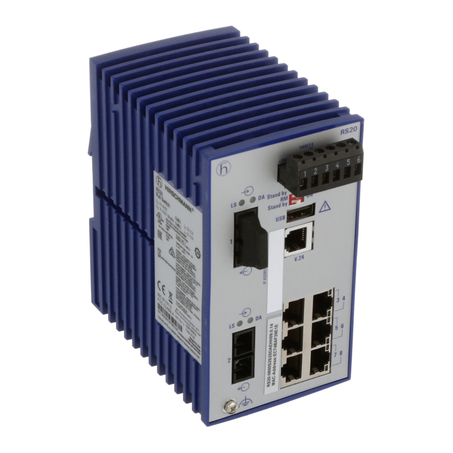
Hirschmann RS20 User Manual
Hide thumbs
Also See for RS20:
- Reference manual (572 pages) ,
- User manual (294 pages) ,
- Programming manual (116 pages)

Subscribe to Our Youtube Channel
Related Manuals for Hirschmann RS20


Summary of Contents for Hirschmann RS20
-
Page 1: User Manual
User Manual Basic Configuration Industrial ETHERNET (Gigabit-)Switch RS20/RS30/RS40, MS20/MS30 UM BasicConfig L2E Technical Support Release 8.0 05/2013 https://hirschmann-support.belden.eu.com... - Page 2 In addition, we refer to the conditions of use specified in the license contract. You can get the latest version of this manual on the Internet at the Hirschmann product site (www.hirschmann.com). Printed in Germany Hirschmann Automation and Control GmbH Stuttgarter Str.
-
Page 3: Table Of Contents
Contents Contents About this Manual Introduction Access to the user interfaces System Monitor Command Line Interface Graphical User Interface Entering the IP Parameters IP Parameter Basics 2.1.1 IP Address (Version 4) 2.1.2 Netmask 2.1.3 Classless Inter-Domain Routing Entering IP parameters via CLI Entering the IP Parameters via HiDiscovery Loading the system configuration from the ACA System configuration via BOOTP... - Page 4 Contents Saving settings 3.2.1 Saving locally (and on the ACA) 3.2.2 Saving in a binary file on a URL 3.2.3 Saving as an offline configuration file on the PC Configuration Signature Loading Software Updates Loading the Software manually from the ACA 4.1.1 Selecting the software to be loaded 4.1.2 Starting the software 4.1.3 Performing a cold start...
- Page 5 Contents Precision Time Protocol 7.3.1 Description of PTP Functions Network Load Control Direct Packet Distribution 8.1.1 Store and Forward 8.1.2 Multi-Address Capability 8.1.3 Aging of learned MAC addresses 8.1.4 Entering Static Addresses 8.1.5 Disabling the Direct Packet Distribution Multicast Application 8.2.1 Description of the Multicast Application 8.2.2 Example of a Multicast Application 8.2.3 Description of IGMP Snooping...
- Page 6 Contents Out-of-band Signaling 9.3.1 Controlling the Signal Contact 9.3.2 Monitoring the Device Status via the Signal Contact 9.3.3 Monitoring the Device Functions via the Signal Contact Port Status Indication Event Counter at Port Level 9.5.1 Detecting Non-matching Duplex Modes Displaying the SFP Status Topology Discovery 9.7.1 Description of Topology-Detection 9.7.2 Displaying the Topology Discovery Results...
-
Page 7: About This Manual
About this Manual About this Manual The “Basic Configuration” user manual contains the information you need to start operating the device. It takes you step by step from the first startup operation through to the basic settings for operation in your environment. The following thematic sequence has proven itself in practice: ... - Page 8 SNMP/OPC gateway. Maintenance Hirschmann is continually working to improve and develop our software. You should regularly check whether there is a new version of the software that provides you with additional benefits. You will find software information and downloads on the product pages of the Hirschmann website.
-
Page 9: Key
The designations used in this manual have the following meanings: List Work step Subheading Link Cross-reference with link Note: A note emphasizes an important fact or draws your attention to a dependency. ASCII representation in user interface Courier Execution in the Graphical User Interface Execution in the Command Line Interface... - Page 10 Bridge A random computer Configuration Computer Server PLC - Programmable logic controller I/O - Robot UM BasicConfig L2E Release 8.0 05/2013...
-
Page 11: Introduction
Introduction Introduction The device has been developed for use in a harsh industrial environment. Accordingly, the installation process has been kept simple. Thanks to the selected default settings, you only have to enter a few settings before starting to operate the device. Note: The changes you make in the dialogs are copied into the volatile memory of the device when you click on "Set". - Page 12 Introduction UM BasicConfig L2E Release 8.0 05/2013...
-
Page 13: Access To The User Interfaces
Access to the user interfaces 1 Access to the user interfaces The device has 3 user interfaces, which you can access via different interfaces: System monitor via the V.24 interface (out-of-band) Command Line Interface (CLI) via the V.24 connection (out-of-band) and Telnet (in-band) ... -
Page 14: System Monitor
Access to the user interfaces 1.1 System Monitor 1.1 System Monitor The system monitor enables you to select the software to be loaded perform a software update start the selected software shut down the system monitor ... - Page 15 Access to the user interfaces 1.1 System Monitor Start the terminal program on the PC and set up a connection with the device. When you boot the device, the message "Press <1> to enter System Monitor 1" appears on the terminal. <...
- Page 16 Access to the user interfaces 1.1 System Monitor Press the <1> key within one second to start system monitor 1. System Monitor (Selected OS: L3P-06.0.00 (2010-09-09 09:09)) Select Boot Operating System Update Operating System Start Selected Operating System End (reset and reboot) Erase main configuration file sysMon1>...
-
Page 17: Command Line Interface
Access to the user interfaces 1.2 Command Line Interface 1.2 Command Line Interface The Command Line Interface enables you to use the functions of the device via a local or remote connection. The Command Line Interface provides IT specialists with a familiar environment for configuring IT devices. - Page 18 Command Line Interface via Telnet. A window for entering the user name appears on the screen. Up to 5 users can access the Command Line Interface. Copyright (c) 2004-2010 Hirschmann Automation and Control GmbH All rights reserved PowerMICE Release L3P-06.0.00...
- Page 19 NOTE: Enter '?' for Command Help. Command help displays all options that are valid for the 'normal' and 'no' command forms. the syntax of a particular command form, please consult the documentation. (Hirschmann Product) > Figure 4: CLI screen after login UM BasicConfig L2E Release 8.0 05/2013...
-
Page 20: Graphical User Interface
Access to the user interfaces 1.3 Graphical User Interface 1.3 Graphical User Interface The user-friendly graphical user interface gives you the option of operating the device from any location in the network via a standard browser such as Mozilla Firefox or Microsoft Internet Explorer. As a universal access tool, the Web browser uses an applet which communicates with the device via the Simple Network Management Protocol (SNMP). - Page 21 Access to the user interfaces 1.3 Graphical User Interface Figure 5: Login window Select the desired language. In the drop-down menu, you select – user, to have read access, or – admin, to have read and write access to the device.
- Page 22 Access to the user interfaces 1.3 Graphical User Interface UM BasicConfig L2E Release 8.0 05/2013...
-
Page 23: Entering The Ip Parameters
Entering the IP Parameters 2 Entering the IP Parameters When you install the device for the first time enter the IP parameters. The device provides the following options for entering the IP parameters during the first installation: Entry using the Command Line Interface (CLI). You choose this “out of band”... - Page 24 Entering the IP Parameters Configuration via DHCP Option 82. You choose this “in-band” method if you want to configure the installed device using DHCP Option 82. You need a DHCP server with Option 82 for this. The DHCP server assigns the configuration data to the device using its physical connection (see on page 47 “System Configuration via DHCP Option...
-
Page 25: Ip Parameter Basics
Entering the IP Parameters 2.1 IP Parameter Basics 2.1 IP Parameter Basics 2.1.1 IP Address (Version 4) The IP addresses consist of 4 bytes. These 4 bytes are written in decimal notation, separated by a decimal point. Since 1992, five classes of IP address have been defined in the RFC 1340. Class Network Host address... -
Page 26: Netmask
Entering the IP Parameters 2.1 IP Parameter Basics Net ID - 7 bits Host ID - 24 bits Class A Net ID - 14 bits Host ID - 16 bits Class B Net ID - 21 bits Host ID - 8 bit s Class C Multicast Group ID - 28 bits Class D... - Page 27 Entering the IP Parameters 2.1 IP Parameter Basics The bits of the host address (host id) that represent the mask are set to one. The remaining bits of the host address in the netmask are set to zero (see the following examples). Example of a netmask: Decimal notation 255.255.192.0...
- Page 28 Entering the IP Parameters 2.1 IP Parameter Basics Decimal notation 129.218.65.17 128 < 129 191 › Class B Binary notation 10000001.11011010.01000001.00010001 Subnetwork 1 Network address Decimal notation 129.218.129.17 128 < 129 191 › Class B Binary notation 10000001.11011010.10000001.00010001 Subnetwork 2 Network address UM BasicConfig L2E Release 8.0 05/2013...
- Page 29 Entering the IP Parameters 2.1 IP Parameter Basics Example of how the network mask is used In a large network it is possible that gateways and routers separate the management agent from its management station. How does addressing work in such a case? Romeo Juliet Lorenzo...
-
Page 30: Classless Inter-Domain Routing
Entering the IP Parameters 2.1 IP Parameter Basics Lorenzo receives the letter and removes the outer envelope. From the inner envelope he recognizes that the letter is meant for Juliet. He places the inner envelope in a new outer envelope and searches his address list (the ARP table) for Juliet's MAC address. - Page 31 Entering the IP Parameters 2.1 IP Parameter Basics Since 1993, RFC 1519 has been using Classless Inter-Domain Routing (CIDR) to provide a solution. CIDR overcomes these class boundaries and supports classless address ranges. With CIDR, you enter the number of bits that designate the IP address range. You represent the IP address range in binary form and count the mask bits that designate the netmask.
-
Page 32: Entering Ip Parameters Via Cli
Entering the IP Parameters 2.2 Entering IP parameters via CLI 2.2 Entering IP parameters via If you do not configure the system via BOOTP/DHCP, DHCP Option 82, the HiDiscovery protocol or the AutoConfiguration Adapter ACA, then you perform the configuration via the V.24 interface using the CLI. Entering IP addresses Connect the PC with terminal program started to the RJ11 socket... - Page 33 NOTE: Enter '?' for Command Help. Command help displays all options that are valid for the 'normal' and 'no' command forms. the syntax of a particular command form, please consult the documentation. (Hirschmann PowerMICE) > Deactivate DHCP. Enter the IP parameters. ...
- Page 34 Entering the IP Parameters 2.2 Entering IP parameters via CLI The default setting of the netmask is 0.0.0.0. IP address of the gateway. You require this entry when installing the device in a different subnetwork as the management station or TFTP server (see on page 29 “Example of how the network mask is used”).
-
Page 35: Entering The Ip Parameters Via Hidiscovery
Entering the IP Parameters 2.3 Entering the IP Parameters via HiDiscovery 2.3 Entering the IP Parameters via HiDiscovery The HiDiscovery protocol enables you to assign IP parameters to the device via the Ethernet. You can easily configure other parameters via the graphical user interface (see the "GUI"... - Page 36 Entering the IP Parameters 2.3 Entering the IP Parameters via HiDiscovery Note: For security reasons, switch off the HiDiscovery function for the device in the graphical user interface, after you have assigned the IP parameters to the device (see on page 48 “Graphical User Interface IP Configuration”).
-
Page 37: Loading The System Configuration From The Aca
Entering the IP Parameters 2.4 Loading the system configuration from the ACA 2.4 Loading the system configuration from the ACA The AutoConfiguration Adapter (ACA) is a device for for saving the device configuration data and saving the device software. If a device becomes inoperative, the ACA allows you to transfer the configuration data to a replacement device of the same type. - Page 38 Entering the IP Parameters 2.4 Loading the system configuration from the ACA Figure 9: Flow chart of loading configuration data from the ACA 1 – Device start-up 2 – ACA plugged-in? 3 – Password in device and ACA identical? 3a – Default password in device? 4 –...
-
Page 39: System Configuration Via Bootp
Entering the IP Parameters 2.5 System configuration via BOOTP 2.5 System configuration via BOOTP When it is started up via BOOTP (bootstrap protocol), a device receives its configuration data in accordance with the “BOOTP process” flow chart (see figure 10). Note: In its delivery state, the device gets its configuration data from the DHCP server. - Page 40 Entering the IP Parameters 2.5 System configuration via BOOTP switch_01:ht=ethernet:ha=008063086501:ip=10.1.112.83:tc=.global: switch_02:ht=ethernet:ha=008063086502:ip=10.1.112.84:tc=.global: Lines that start with a ‘#’ character are comment lines. The lines under “.global:” make the configuration of several devices easier. With the template (tc) you allocate the global configuration data (tc=.global:) to each device .
- Page 41 Entering the IP Parameters 2.5 System configuration via BOOTP Start-up Load default configuration Device in initalization Device runs with settings from local flash Send DHCP DHCP/ BOOTP BOOTP? Requests Reply from Save IP parameter DHCP/BOOTP and config file URL server? locally initialize IP stack with IP parameters...
- Page 42 Entering the IP Parameters 2.5 System configuration via BOOTP Load remote Start tftp process configuration from with config URL of DHCP? file URL of DHCP tftp successful? Load transferred config file Save transferred config file local and set boot configuration to local Loading of configurations data...
- Page 43 Entering the IP Parameters 2.5 System configuration via BOOTP Note: The loading process started by DHCP/BOOTP (see on page 39 “System configuration via BOOTP”) shows the selection of “from URL & save locally” in the “Load” frame. If you get an error message when saving a configuration, this could be due to an active loading process.
-
Page 44: System Configuration Via Dhcp
Entering the IP Parameters 2.6 System Configuration via DHCP 2.6 System Configuration via DHCP The DHCP (Dynamic Host Configuration Protocol) is a further development of BOOTP, which it has replaced. The DHCP additionally allows the configuration of a DHCP client via a name instead of via the MAC address. For the DHCP, this name is known as the “client identifier”... - Page 45 Entering the IP Parameters 2.6 System Configuration via DHCP Option Meaning Host Name NTP server Client Identifier TFTP Server Name Bootfile Name Table 3: DHCP options which the device requests The advantage of using DHCP instead of BOOTP is that the DHCP server can restrict the validity of the configuration parameters (“Lease”) to a specific time period (known as dynamic address allocation).
- Page 46 Entering the IP Parameters 2.6 System Configuration via DHCP # Host berta requests IP configuration # with her MAC address host berta { hardware ethernet 00:80:63:08:65:42; fixed-address 10.1.112.82; # Host hugo requests IP configuration # with his client identifier. host hugo { option dhcp-client-identifier "hugo";...
-
Page 47: System Configuration Via Dhcp Option
Entering the IP Parameters 2.7 System Configuration via DHCP Option 82 2.7 System Configuration via DHCP Option 82 As with the classic DHCP, on startup an agent receives its configuration data according to the “BOOTP/DHCP process” flow chart (see figure 10). -
Page 48: Graphical User Interface Ip Configuration
Entering the IP Parameters 2.8 Graphical User Interface IP Confi- guration 2.8 Graphical User Interface IP Configuration Use the Basic Settings:Network dialog to define the source from which the device receives its IP parameters after startup, assign the IP parameters and VLAN ID, and configure the HiDiscovery access. - Page 49 Entering the IP Parameters 2.8 Graphical User Interface IP Confi- guration Figure 13: Network parameters dialog Under “Mode”, you enter where the device gets its IP parameters: In the BOOTP mode, the configuration is via a BOOTP or DHCP server on the basis of the MAC address of the device.
- Page 50 Entering the IP Parameters 2.8 Graphical User Interface IP Confi- guration The “VLAN” frame enables you to assign a VLAN to the management CPU of the device. If you enter 0 here as the VLAN ID (not included in the VLAN standard version), the management CPU will then be accessible from all VLANs.
-
Page 51: Faulty Device Replacement
Entering the IP Parameters 2.9 Faulty Device Replacement 2.9 Faulty Device Replacement The device provides 2 plug-and-play solutions for replacing a faulty device with a device of the same type (faulty device replacement): Configuring the new device using an AutoConfiguration Adapter (see on page 37 “Loading the system configuration from the ACA”) ... - Page 52 Entering the IP Parameters 2.9 Faulty Device Replacement UM BasicConfig L2E Release 8.0 05/2013...
-
Page 53: Loading/Saving Settings
Loading/saving settings 3 Loading/saving settings The device saves settings such as the IP parameters and the port configuration in the temporary memory. These settings are lost when you switch off or reboot the device. The device allows you to do the following: ... -
Page 54: Loading Settings
Loading/saving settings 3.1 Loading settings 3.1 Loading settings When it is restarted, the device loads its configuration data from the local non-volatile memory. The prerequisites for this are: You have not connected an AutoConfiguration Adapter (ACA) and the IP configuration is “local”. During a restart, the device also allows you to load settings from the following sources: ... -
Page 55: Loading From The Local Non-Volatile Memory
Loading/saving settings 3.1 Loading settings Note: When loading a configuration, hold off any accesses to the device until it has loaded the configuration file and applied the new configuration settings. Depending on the device type and the extent of the configuration settings, this process can take between 10 and 200 seconds. -
Page 56: Loading From A File
Loading/saving settings 3.1 Loading settings 3.1.2 Loading from a file The device allows you to load the configuration data from a file in the connected network if there is no AutoConfiguration Adapter connected to the device. Select the Basics: Load/Save dialog. ... - Page 57 Loading/saving settings 3.1 Loading settings Example of loading from a tftp server Before downloading a file from the tftp server, you have to save the configuration file in the corresponding path of the tftp servers with the file name, e.g. switch/switch_01.cfg (see on page 62 “Saving in a binary file on a URL”).
-
Page 58: Resetting The Configuration To The Default Settings
Loading/saving settings 3.1 Loading settings Note: The loading process started by DHCP/BOOTP (see on page 39 “System configuration via BOOTP”) shows the selection of “from URL & save locally” in the “Load” frame. If you get an error message when saving a configuration, this could be due to an active loading process. -
Page 59: Loading From The Autoconfiguration Adapter
Loading/saving settings 3.1 Loading settings 3.1.4 Loading from the AutoConfiguration Adapter Loading a configuration during the boot procedure If you connect an ACA to the device and if the passwords on the device are in the default setting, missing, or the same as those on the ACA, the device automatically loads its configuration from the ACA during the boot procedure. -
Page 60: Saving Settings
Loading/saving settings 3.2 Saving settings 3.2 Saving settings In the “Save” frame, you have the option to save the current configuration on the device, save the current configuration in binary form in a file under the specified URL, ... - Page 61 Loading/saving settings 3.2 Saving settings Note: After you have successfully saved the configuration on the device, the device sends a trap hmConfigurationSavedTrap together with the information about the AutoConfiguration Adapter (ACA), if one is connected. When you change the configuration for the first time after saving it, the device sends a trap hmConfigurationChangedTrap.
-
Page 62: Saving In A Binary File On A Url
Loading/saving settings 3.2 Saving settings 3.2.2 Saving in a binary file on a URL The device allows you to save the current configuration data in a file in the connected network. Note: The configuration file includes all configuration data, including the password. -
Page 63: Saving As An Offline Configuration File On The Pc
Loading/saving settings 3.2 Saving settings 3.2.3 Saving as an offline configuration file on the The device allows you to save the current configuration data for the offline configurator in XML form in a file on your PC. Select the Basics: Load/Save dialog. -
Page 64: Configuration Signature
Loading/saving settings 3.3 Configuration Signature 3.3 Configuration Signature The device assigns a checksum or signature to identify a configuration in a way that changes to a configuration are visible. Every time you save a configuration, the device generates a random sequence of numbers and/or letters for the configuration signature. -
Page 65: Loading Software Updates
Loading Software Updates 4 Loading Software Updates Hirschmann is working constantly to improve the performance of their procucts. Therefore, on the Hirschmann web page (www.hirschmann.com) you may find a newer release of the device software than the one installed on your device. - Page 66 Loading Software Updates Loading the software The device gives you 4 options for loading the software: manually from the ACA (out-of-band), automatically from the ACA (out-of-band), via TFTP from a tftp server (in-band) and via a file selection dialog from your PC. Note: The existing configuration of the device is still there after the new software is installed.
-
Page 67: Loading The Software Manually From The Aca
Loading Software Updates 4.1 Loading the Software manually from the ACA 4.1 Loading the Software manually from the ACA You can connect the AutoConfiguration Adapter (ACA) to a USB port of your PC like a conventional USB stick and copy the device software into the main directory of the ACA. -
Page 68: Selecting The Software To Be Loaded
Loading Software Updates 4.1 Loading the Software manually from the ACA 4.1.1 Selecting the software to be loaded In this menu item of the system monitor, you select one of two possible software releases that you want to load. The following window appears on the screen: Select Operating System Image (Available OS: Selected: 05.0.00 (2009-08-07 06:05), Backup: 04.2.00 (2009-07-06 06:05 (Locally selected: 05.0.00 (2009-08-07 06:05)) -
Page 69: Starting The Software
Loading Software Updates 4.1 Loading the Software manually from the ACA Swap OS images The memory of the device provides space for two images of the software. This allows you, for example, to load a new version of the software without deleting the existing version. -
Page 70: Performing A Cold Start
Loading Software Updates 4.1 Loading the Software manually from the ACA allows you to start the software selected. 4.1.3 Performing a cold start This menu item (End (reset and reboot)) of the system monitor allows you to reset the hardware of the device and perform a restart. UM BasicConfig L2E Release 8.0 05/2013... -
Page 71: Automatic Software Update By Aca
Loading Software Updates 4.2 Automatic software update by 4.2 Automatic software update by ACA For a software update via the ACA, first copy the new device software into the main directory of the AutoConfiguration Adapter. If the version of the software on the ACA is newer or older than the version on the device, the device performs a software update. - Page 72 Loading Software Updates 4.2 Automatic software update by One of the following messages in the log file indicates the result of the update process: S_watson_AUTOMATIC_SWUPDATE_SUCCESSFUL: Update completed successfully. S_watson_AUTOMATIC_SWUPDATE_FAILED_WRONG_FILE: Update failed. Reason: incorrect file. S_watson_AUTOMATIC_SWUPDATE_FAILED_SAVING_FILE: Update failed. Reason: error when saving. ...
-
Page 73: Loading The Software From The Tftp Server
Loading Software Updates 4.3 Loading the software from the TFTP server 4.3 Loading the software from the TFTP server For a software update via TFTP, you need a TFTP server on which the software to be loaded is stored (see on page 200 “TFTP Server for Software Updates”). - Page 74 Loading Software Updates 4.3 Loading the software from the TFTP server Figure 16: Software update dialog After successfully loading it, you activate the new software: Select the dialog Basic Settings:Restart and perform a cold start. In a cold start, the device reloads the software from the permanent memory, restarts, and performs a self-test.
-
Page 75: Loading The Software Via File Selection
Loading Software Updates 4.4 Loading the Software via File Selection 4.4 Loading the Software via File Selection For a software update via a file selection window, the device software must be on a data carrier that you can access from your PC. ... -
Page 76: Bootcode Update Via Tftp
Loading Software Updates 4.5 Bootcode Update via TFTP 4.5 Bootcode Update via TFTP In some cases, a boot code update is necessary. Perform a bootcode update when the service desk requests. 4.5.1 Updating the Bootcode file For a tftp update, you need a tftp server to store the bootcode. The URL identifies the path to the bootcode stored on the tftp server. -
Page 77: Configuring The Ports
Configuring the Ports 5 Configuring the Ports The port configuration consists of: Switching the port on and off Selecting the operating mode Activating the display of connection error messages Configuring Power over ETHERNET. Switching the port on and off ... - Page 78 Configuring the Ports Disable unused module slots This function is available for the MS, PowerMICE, MACH102 and MACH4000 devices. When you plug a module in an empty slot on modular devices, the device configures the module with the default settings. The default settings allow access to the network.
-
Page 79: Global Settings
Configuring the Ports Nominal power for OCTOPUS 8M-PoE: The device provides the nominal power for the sum of all PoE ports, plus a power reserve. Since the device draws its PoE voltage from outside, it cannot know what the nominal power is. Instead, the device therefore assumes a nominal power value of 15 Watt per PoE port. -
Page 80: Port Settings
Configuring the Ports Port settings – For devices with PoE select the Basic Settings:Power over Ethernet dialog. – For devices with PoE+ select the Basic Settings:Power over Ethernet Plus:Port dialog. The table only shows ports that support PoE. In the “POE on” column, you can enable/disable PoE at this port. ... - Page 81 Configuring the Ports Switch on PoE power supply OCTOPUS PoE devices let you switch on the PoE power supply before loading and starting the software. This means that the connected PoE devices (powered devices) are supplied with the PoE voltage more quickly and the start phase of the whole network is shorter.
- Page 82 Configuring the Ports Switch on the "Cold start if error detected“ function. #selftest reboot-on-error enable Switch on the "Cold start only if serious error #selftest reboot-on-error detected“ function. seriousOnly Switch off the "Cold start if error detected“ function #selftest reboot-on-error (enabled in the as-delivered state).
-
Page 83: Assistance In The Protection From Unauthorized Access
Assistance in the Protection from Unauthorized Access 6 Assistance in the Protection from Unauthorized Access The device provides the following functions to help prevent unauthorised accesses. Password for SNMP access Telnet/internet access can be switched off Restricted Management access ... -
Page 84: Protecting The Device
Assistance in the Protection from 6.1 Protecting the device Unauthorized Access 6.1 Protecting the device If you want to maximize the protection of the device against unauthorized access in just a few steps, you can perform the following steps on the device as required: ... -
Page 85: Password For Snmp Access
Assistance in the Protection from 6.2 Password for SNMP access Unauthorized Access 6.2 Password for SNMP access 6.2.1 Description of password for SNMP access A network management station communicates with the device via the Simple Network Management Protocol (SNMP). Every SNMP packet contains the IP address of the sending computer and the password with which the sender of the packet wants to access the device MIB. -
Page 86: Entering The Password For Snmp Access
Assistance in the Protection from 6.2 Password for SNMP access Unauthorized Access 6.2.2 Entering the password for SNMP access Select the Security:Password/SNMP Access dialog. This dialog gives you the option of changing the read and read/write passwords for access to the device via the graphical user interface, via the CLI, and via SNMPv3 (SNMP version 3). - Page 87 Assistance in the Protection from 6.2 Password for SNMP access Unauthorized Access Figure 18: Password/SNMP Access dialog Note: If you do not know a password with “read/write” access, you will not have write access to the device. Note: For security reasons, the device does not display the passwords. Make a note of every change.
- Page 88 Assistance in the Protection from 6.2 Password for SNMP access Unauthorized Access Select the Security:SNMPv1/v2 access dialog. With this dialog you can select the access via SNMPv1 or SNMPv2. In the state on delivery, both protocols are activated. You can thus manage the device with HiVision and communicate with earlier versions of SNMP.
- Page 89 Assistance in the Protection from 6.2 Password for SNMP access Unauthorized Access Figure 19: SNMPv1/v2 access dialog To create a new line in the table click “Create”. To delete an entry, select the line in the table and click “Remove”. 6.2.3 Description of Telnet Access The Telnet server of the device allows you to configure the device using the...
- Page 90 Assistance in the Protection from 6.2 Password for SNMP access Unauthorized Access Note: The Command Line Interface (out-of-band) and the Security:Telnet/Web/SSH Access dialog in the graphical user interface allows you to reactivate the Telnet server. 6.2.4 Description of Web Access (http) The device's Web server allows you to configure the device by using the graphical user interface.
- Page 91 Assistance in the Protection from 6.2 Password for SNMP access Unauthorized Access Select the Security:Telnet/Web access dialog. Disable the server to which you want to refuse access. Switch to the privileged EXEC mode. enable Switch to the Configuration mode. configure Switch to the configuration mode for CLI.
- Page 92 Assistance in the Protection from 6.2 Password for SNMP access Unauthorized Access Certificate An X.509/PEM Standard certificate (Public Key Infrastructure) is required for the encryption. In the as-delivered state, a self-generated certificate is already present on the device. You can create an X509/PEM certificate using the following CLI command: # ip https certgen ...
- Page 93 Assistance in the Protection from 6.2 Password for SNMP access Unauthorized Access Switch to Privileged EXEC mode. enable Switch on HTTPS-server. # ip https server Set the HTTPS port number for a secure HTTP # ip https port <port_no> connection. - As-delivered state: 443.
-
Page 94: Hidiscovery Access
Assistance in the Protection from 6.3 HiDiscovery Access Unauthorized Access 6.3 HiDiscovery Access 6.3.1 Description of the HiDiscovery Protocol The HiDiscovery protocol allows you to allocate an IP address to the device on the basis of its MAC address (see on page 35 “Entering the IP Parameters HiDiscovery”). -
Page 95: Port Access Control
Assistance in the Protection from 6.4 Port access control Unauthorized Access 6.4 Port access control 6.4.1 Description of the port access control You can configure the device in such a way that it helps to protect every port from unauthorized access. Depending on your selection, the device checks the MAC address or the IP address of the connected device. -
Page 96: Application Example For Port Access Control
Assistance in the Protection from 6.4 Port access control Unauthorized Access 6.4.2 Application Example for Port Access Control You have a LAN connection in a room that is accessible to everyone. To set the device so that only defined users can use this LAN connection, activate the port access control on this port. - Page 97 Assistance in the Protection from 6.4 Port access control Unauthorized Access In the table, click on the row of the port to be protected, in the “Allowed IP addresses” cell. Enter in sequence: – the IP subnetwork group: 10.0.1.228 –...
-
Page 98: Login Banner
Assistance in the Protection from 6.5 Login Banner Unauthorized Access 6.5 Login Banner The device gives you the option of displaying a greeting text to users before they login to the device. The users see this greeting text in the login dialog of the graphical user interface (GUI) and of the Command Line Interface (CLI). -
Page 99: Synchronizing The System Time In The Network
Synchronizing the System Time in the Network 7 Synchronizing the System Time in the Network The actual meaning of the term “real time” depends on the time requirements of the application. The device provides two options with different levels of accuracy for synchronizing the time in your network. -
Page 100: Setting The Time
Synchronizing the System Time in the 7.1 Setting the time Network 7.1 Setting the time If no reference clock is available, you have the option of entering the system time in a device and then using it like a reference clock (see on page 104 “Configuring SNTP”). - Page 101 Synchronizing the System Time in the 7.1 Setting the time Network Time Source displays the source of the following time data. The device automatically selects the source with the greatest accuracy. Possible sources are: local, ptp and sntp. The source is initially local.
-
Page 102: Sntp
Synchronizing the System Time in the 7.2 SNTP Network 7.2 SNTP 7.2.1 Description of SNTP The Simple Network Time Protocol (SNTP) enables you to synchronize the system time in your network. The device supports the SNTP client and the SNTP server function. The SNTP server makes the UTC (Universal Time Coordinated) available. -
Page 103: Preparing The Sntp Configuration
Synchronizing the System Time in the 7.2 SNTP Network 7.2.2 Preparing the SNTP Configuration To get an overview of how the time is passed on, draw a network plan with the devices participating in SNTP. When planning, bear in mind that the accuracy of the time depends on the signal runtime. -
Page 104: Configuring Sntp
Synchronizing the System Time in the 7.2 SNTP Network 7.2.3 Configuring SNTP Select the Time:SNTP dialog. Operation In this frame you switch the SNTP function on/off globally. SNTP Status The “Status message” displays statuses of the SNTP client as one or more test messages, e.g. - Page 105 Synchronizing the System Time in the 7.2 SNTP Network SNTP server configuration In "Server-Status", switch the device's SNTP server on/off. In “Anycast destination address” you enter the IP address to which the SNTP server of the device sends its SNTP packets (see table ...
- Page 106 Synchronizing the System Time in the 7.2 SNTP Network Figure 23: SNTP Dialog Device 192.168.1.1 192.168.1.2 192.168.1.3 Operation Server destination address 0.0.0.0 0.0.0.0 0.0.0.0 Server VLAN ID Send interval Client external server address 192.168.1.0 192.168.1.1 192.168.1.2 Request interval Accept Broadcasts Table 5: Settings for the example (see figure 22)
-
Page 107: Precision Time Protocol
Synchronizing the System Time in the 7.3 Precision Time Protocol Network 7.3 Precision Time Protocol 7.3.1 Description of PTP Functions Precise time management is required for running time-critical applications via a LAN. The IEEE 1588 standard with the Precision Time Protocol (PTP) describes a procedure that determines the best master clock in a LAN and thus enables precise synchronization of the clocks in this LAN. - Page 108 Synchronizing the System Time in the 7.3 Precision Time Protocol Network PTPv1 PTPv2 Specification Stratum Clock class number Indicates the reference clock that can be synchronized via an external connection. Indicates the reference clock that cannot be synchronized via an external connection.
- Page 109 Synchronizing the System Time in the 7.3 Precision Time Protocol Network Reference Local (Master clock) (Slave clock) Delay + Jitter Delay + Jitter Delay + Jitter Precision Time Protocol (Application Layer) UDP User Datagramm Protocol (Transport Layer) Internet Protocol (Network Layer) MAC Media Access Control Physical Layer Figure 24: Delay and jitter for clock synchronization...
- Page 110 Synchronizing the System Time in the 7.3 Precision Time Protocol Network UM BasicConfig L2E Release 8.0 05/2013...
-
Page 111: Network Load Control
Network Load Control 8 Network Load Control To optimize the data transmission, the device provides you with the following functions for controlling the network load: Settings for direct packet distribution (MAC address filter) Multicast settings Rate limiter ... -
Page 112: Direct Packet Distribution
Network Load Control 8.1 Direct Packet Distribution 8.1 Direct Packet Distribution With direct packet distribution, you help protect the device from unnecessary network loads. The device provides you with the following functions for direct packet distribution: Store-and-forward Multi-address capability ... -
Page 113: Aging Of Learned Mac Addresses
Network Load Control 8.1 Direct Packet Distribution The device can learn up to 8,000 addresses. This is necessary if more than one terminal device is connected to one or more ports. It is thus possible to connect several independent subnets to the device. 8.1.3 Aging of learned MAC addresses The device monitors the age of the learned addresses. -
Page 114: Entering Static Addresses
Network Load Control 8.1 Direct Packet Distribution 8.1.4 Entering Static Addresses An important function of the device is the filter function. It selects data packets according to defined patterns, known as filters. These patterns are assigned distribution rules. This means that a data packet received by a device at a port is compared with the patterns. -
Page 115: Disabling The Direct Packet Distribution
Network Load Control 8.1 Direct Packet Distribution Select the Switching:Filters for MAC Addresses dialog. Each row of the filter table represents one filter. Filters specify the way in which data packets are sent. They are set automatically by the Switch (learned status) or created manually. -
Page 116: Multicast Application
Network Load Control 8.2 Multicast Application 8.2 Multicast Application 8.2.1 Description of the Multicast Application The data distribution in the LAN differentiates between 3 distribution classes on the basis of the addressed recipients: Unicast - one recipient Multicast - a group of recipients ... -
Page 117: Example Of A Multicast Application
Network Load Control 8.2 Multicast Application 8.2.2 Example of a Multicast Application The cameras for monitoring machines normally transmit their images to monitors located in the machine room and to the control room. In an IP transmission, a camera sends its image data with a Multicast address via the network. -
Page 118: Description Of Igmp Snooping
Network Load Control 8.2 Multicast Application 8.2.3 Description of IGMP Snooping The Internet Group Management Protocol (IGMP) describes the distribution of Multicast information between routers and terminal devices on Layer 3. Routers with an active IGMP function periodically send queries to find out which IP Multicast group members are connected to the LAN. -
Page 119: Setting Igmp Snooping
Network Load Control 8.2 Multicast Application 8.2.4 Setting IGMP Snooping Select the Switching:Multicast:IGMP dialog. Operation The “Operation” frame allows you to enable/disable IGMP Snooping globally for the entire device. If IGMP Snooping is disabled, then the device does not evaluate Query and Report packets received, ... - Page 120 Network Load Control 8.2 Multicast Application IGMP Settings “Current querier IP address” shows you the IP address of the device that has the query function. In “Max. Response Time” you specify the period within which the Multicast group members respond to a query (valid values: 1-3,598 s, default setting: 10 s).
- Page 121 Network Load Control 8.2 Multicast Application Parameter Protocol Version Value Range Default Setting Max. Response Time 1, 2 1-25 seconds 10 seconds 1-3,598 seconds Transmit Interval 1, 2, 3 2-3,599 seconds 125 seconds Group Membership Interval 1, 2, 3 3-3,600 seconds 260 seconds Table 7: Value range for Max.
- Page 122 Network Load Control 8.2 Multicast Application Known Multicasts In this frame you can determine how the device in IGMP mode sends packets with known MAC/IP Multicast addresses that were learned through IGMP Snooping. “Send to query and registered ports”. The device sends the packets with a known MAC/IP Multicast address to all query ports and to registered ports.
- Page 123 IGMP requests (disabled=as-delivered state). This table column also lets you send IGMP Report messages to: other selected ports (enable) or connected Hirschmann devices (automatic). “Learned Query Port” This table column shows you at which ports the device has received IGMP queries, if “disable”...
- Page 124 Network Load Control 8.2 Multicast Application Figure 26: IGMP Snooping dialog UM BasicConfig L2E Release 8.0 05/2013...
-
Page 125: Rate Limiter
Network Load Control 8.3 Rate Limiter 8.3 Rate Limiter 8.3.1 Description of the Rate Limiter To ensure reliable operation at a high level of traffic, the device allows you to limit the rate of traffic at the ports. Entering a limit rate for each port determines the amount of traffic the device is permitted to transmit and receive. -
Page 126: Rate Limiter Settings
Network Load Control 8.3 Rate Limiter 8.3.2 Rate limiter settings Select the Switching:Rate Limiter dialog. "Ingress Limiter (kbit/s)" allows you to enable or disable the input limiting function for all ports. "Egress Limiter (Pkt/s)" allows you to enable or disable the broadcast output limiter function at all ports. - Page 127 Network Load Control 8.3 Rate Limiter Figure 27: Rate limiter UM BasicConfig L2E Release 8.0 05/2013...
-
Page 128: Qos/Priority
Network Load Control 8.4 QoS/Priority 8.4 QoS/Priority 8.4.1 Description of Prioritization This function helps prevent time-critical data traffic such as language/video or real-time data from being disrupted by less time-critical data traffic during periods of heavy traffic. By assigning high traffic classes for time-critical data and low traffic classes for less time-critical data, this provides optimal data flow for time-critical data traffic. -
Page 129: Vlan Tagging
Network Load Control 8.4 QoS/Priority Data packets can contain prioritizing/QoS information: VLAN priority based on IEEE 802.1Q/ 802.1D (Layer 2) 8.4.2 VLAN tagging The VLAN tag is integrated into the MAC data frame for the VLAN and Prioritization functions in accordance with the IEEE 802 1Q standard. The VLAN tag consists of 4 bytes. - Page 130 Network Load Control 8.4 QoS/Priority Note: Network protocols and redundancy mechanisms use the highest traffic class 3. Therefore, select other traffic classes for application data. 42-1500 Octets min. 64, max. 1522 Octets Figure 28: Ethernet data packet with tag 4 Octets Figure 29: Tag format UM BasicConfig L2E Release 8.0 05/2013...
-
Page 131: Ip Tos / Diffserv
Network Load Control 8.4 QoS/Priority When using VLAN prioritizing, note the following special features: End-to-end prioritizing requires the VLAN tags to be transmitted to the entire network, which means that all network components must be VLAN- capable. Routers cannot receive or send packets with VLAN tags via port-based router interfaces. -
Page 132: Differentiated Services
Network Load Control 8.4 QoS/Priority Bits (0-2): IP Precedence Defined Bits (3-6): Type of Service Defined Bit (7) 010 - Immediate 001 - Priority 000 - Routine Table 9: ToS field in the IP header Differentiated Services The Differentiated Services field in the IP header (see figure 30) newly defined in RFC 2474 - often known as the DiffServ code point or DSCP -... - Page 133 Network Load Control 8.4 QoS/Priority The PHB class selector assigns the 7 possible IP precedence values from the old ToS field to specific DSCP values, thus ensuring the downwards compatibility. ToS Meaning Precedence Value Assigned DSCP Network Control CS7 (111000) Internetwork Control CS6 (110000) Critical...
-
Page 134: Handling Of Received Priority Information
Network Load Control 8.4 QoS/Priority 8.4.4 Handling of Received Priority Information The device offers three options, which can be applied globally to all ports and determine how it treats received data packets that contain a priority indicator. trust dot1p The device assigns VLAN-tagged packets to the different traffic classes according to their VLAN priorities. -
Page 135: Handling Of Traffic Classes
Network Load Control 8.4 QoS/Priority 8.4.5 Handling of traffic classes For the handling of traffic classes, the device provides: Strict Priority Description of Strict Priority With the Strict Priority setting, the device first transmits all data packets that have a higher traffic class (higher priority) before transmitting a data packet with the next highest traffic class. - Page 136 Network Load Control 8.4 QoS/Priority Switch to the privileged EXEC mode. enable Switch to the Configuration mode. configure Switch to the Interface Configuration mode of interface 1/1 interface 1/1. Assigns port priority 3 to interface 1/1. vlan priority 3 Switch to the Configuration mode. exit Assigning VLAN priority to a traffic class ...
- Page 137 Network Load Control 8.4 QoS/Priority Switch to the privileged EXEC mode. enable Switch to the Configuration mode. configure Assign traffic class 1 to DSCP CS1. classofservice ip-dscp-mapping cs1 1 show classofservice ip-dscp-mapping IP DSCP Traffic Class ------------- ------------- 0(be/cs0) 8(cs1) Always assign the DSCP priority to received IP data ...
- Page 138 Network Load Control 8.4 QoS/Priority Switch to the privileged EXEC mode. enable Assign the value 7 to the management priority so network priority dot1p-vlan that management packets with the highest priority are sent. Switch to the privileged EXEC mode. exit Displays the management VLAN priority.
- Page 139 Network Load Control 8.4 QoS/Priority System IP Address......10.0.1.116 Subnet Mask........255.255.255.0 Default Gateway........ 10.0.1.200 Burned In MAC Address......00:80:63:51:7A:80 Network Configuration Protocol (BootP/DHCP)..None DHCP Client ID (same as SNMP System Name).."PowerMICE-517A80" Network Configuration Protocol HiDiscovery..Read-Write Management VLAN ID......1 Management VLAN Priority.......
-
Page 140: Flow Control
Network Load Control 8.5 Flow Control 8.5 Flow Control 8.5.1 Description of Flow Control Flow control is a mechanism which acts as an overload protection for the device. During periods of heavy traffic, it holds off additional traffic from the network. - Page 141 Before the send queue of port 2 overflows, the device sends a request to Workstation 2 to include a small break in the sending transmission. Note: The devices RS20/30/40, MS20/30, Octopus, MACH 100, RSR and MACH 1000 support flow control in full duplex mode only.
-
Page 142: Setting The Flow Control
Network Load Control 8.5 Flow Control Note: The devices RS20/30/40, MS20/30, Octopus, MACH 100, RSR and MACH 1000 do not support flow control in half duplex mode. 8.5.2 Setting the Flow Control Select the Basics:Port Configuration dialog. In the "Flow Control on" column, you checkmark this port to specify that flow control is active here. -
Page 143: Vlans
Network Load Control 8.6 VLANs 8.6 VLANs 8.6.1 VLAN Description In the simplest case, a virtual LAN (VLAN) consists of a group of network participants in one network segment who can communicate with each other as if they belonged to a separate LAN. More complex VLANs span out over multiple network segments and are also based on logical (instead of only physical) connections between network participants. -
Page 144: Examples Of Vlans
Network Load Control 8.6 VLANs 8.6.2 Examples of VLANs The following practical examples provide a quick introduction to the structure of a VLAN. Example 1 VLAN VLAN Figure 32: Example of a simple port-based VLAN The example shows a minimal VLAN configuration (port-based VLAN). An administrator has connected multiple terminal devices to a transmission device and assigned them to 2 VLANs. - Page 145 Network Load Control 8.6 VLANs Terminal Port Port VLAN identifier (PVID) Table 12: Ingress table VLANID Port Table 13: Egress table Proceed as follows to perform the example configuration: Configure VLAN Open the dialog. Switching:VLAN:Static UM BasicConfig L2E Release 8.0 05/2013...
- Page 146 Network Load Control 8.6 VLANs Figure 33: Creating and naming new VLANs Click on "Create" to open the window for entering the VLAN ID. Assign VLAN ID 2 to the VLAN. Click "OK". You give this VLAN the name VLAN2 by clicking on the field and entering the name.
- Page 147 Network Load Control 8.6 VLANs Display the current VLAN configuration. show vlan brief Max. VLAN ID........4042 Max. supported VLANs......Number of currently configured VLANs... VLAN 0 Transparent Mode (Prio. Tagged Frames).. Disabled VLAN ID VLAN Name VLAN Type VLAN Creation Time ---- -------------------------------- --------- ------------------ VLAN1 Default...
- Page 148 Network Load Control 8.6 VLANs Figure 35: Assigning and saving "Port VLAN ID", "Acceptable Frame Types" and "Ingress Filtering" Assign the Port VLAN ID of the related VLANs (2 or 3) to the individual ports - see table. Because terminal devices usually send data packets as untagged, you select the admitAll setting for the "Acceptable Frame Types".
- Page 149 Network Load Control 8.6 VLANs Switch to the interface configuration mode for interface 1/2 port 1.2. vlan participation include 3 Port 1/2 becomes member untagged in VLAN 3. Port 1/2 is assigned the port VLAN ID 3. vlan pvid 3 Switch to the Configuration mode.
- Page 150 Network Load Control 8.6 VLANs Example 2 Figure 36: Example of a more complex VLAN configuration The second example shows a more complex configuration with 3 VLANs (1 to 3). Along with the Switch from example 1, you use a 2nd Switch (on the right in the example).
- Page 151 Network Load Control 8.6 VLANs The egress table specifies at which ports the Switch may send the frames from this VLAN. Your entry also defines whether the Switch marks (tags) the Ethernet frames sent from this port. T = with tag field (T = tagged, marked) ...
- Page 152 Network Load Control 8.6 VLANs VLAN ID Port Table 17: Egress table for device on right The communication relationships here are as follows: terminal devices at ports 1 and 4 of the left device and terminal devices at ports 2 and 4 of the right device are members of VLAN 2 and can thus communicate with each other.
- Page 153 Network Load Control 8.6 VLANs Figure 37: Creating and naming new VLANs Click on "Create" to open the window for entering the VLAN ID. Assign VLAN ID 2 to the VLAN. You give this VLAN the name VLAN2 by clicking on the field and entering the name.
- Page 154 Network Load Control 8.6 VLANs Display the current VLAN configuration. show vlan brief Max. VLAN ID........4042 Max. supported VLANs......Number of currently configured VLANs... VLAN 0 Transparent Mode (Prio. Tagged Frames).. Disabled VLAN ID VLAN Name VLAN Type VLAN Creation Time ---- -------------------------------- --------- ------------------ VLAN1 Default...
- Page 155 Network Load Control 8.6 VLANs Open the dialog. Switching:VLAN:Port Figure 39: Assigning and saving "Port VLAN ID", "Acceptable Frame Types" and "Ingress Filtering" Assign the ID of the related VLANs (1 to 3) to the individual ports. Because terminal devices usually send data packets as untagged, you select the admitAll setting for the terminal device ports.
- Page 156 Network Load Control 8.6 VLANs vlan participation include 3 Port 1/1 becomes member untagged in VLAN 3. Port 1/1 becomes member tagged in VLAN 3. vlan tagging 3 Port 1/1 is assigned the port VLAN ID 1. vlan pvid 1 Port 1/1 ingress filtering is activated.
-
Page 157: Operation Diagnosis
Operation Diagnosis 9 Operation Diagnosis The device provides you with the following diagnostic tools: Sending traps Monitoring the device status Out-of-band signaling via signal contact Port status indication Event counter at port level Detecting non-matching duplex modes ... -
Page 158: Sending Traps
Operation Diagnosis 9.1 Sending Traps 9.1 Sending Traps The device reports unusual events which occur during normal operation immediately to the management station. This is done by messages called traps that bypass the polling procedure ("Polling" means querying the data stations at regular intervals). -
Page 159: List Of Snmp Traps
Operation Diagnosis 9.1 Sending Traps 9.1.1 List of SNMP traps The following table shows a list of the traps that can be sent by the device. Trap name Meaning authenticationFailure this is sent if a station attempts to access an agent without authorisation. -
Page 160: Snmp Traps When Booting
Operation Diagnosis 9.1 Sending Traps Trap name Meaning hmAddressRelearnDetectT this is sent if Address Relearn Detection is active and the relearn threshold for MAC addresses on different ports is exceeded. This process indicates high probability of a loop situation on the network. -
Page 161: Configuring Traps
Operation Diagnosis 9.1 Sending Traps 9.1.3 Configuring Traps Select the Diagnostics:Status Configuration: Alarms (Traps) dialog. This dialog allows you to determine which events trigger an alarm (trap) and where these alarms should be sent. Click on "Create". In the "IP Address“ column, enter the IP address of the management station to which the traps should be sent. - Page 162 Operation Diagnosis 9.1 Sending Traps The events which can be selected are: Name Meaning Authentication The device has rejected an unauthorized access attempt (see the Access for IP Addresses and Port Security dialog). Link Up/Down At one port of the device, the link to another device has been established/interrupted.
-
Page 163: Monitoring The Device Status
Operation Diagnosis 9.2 Monitoring the Device Status 9.2 Monitoring the Device Status The device status provides an overview of the overall condition of the device. Many process visualization systems record the device status for a device in order to present its condition in graphic form. The device displays its current status as "Error"... -
Page 164: Configuring The Device Status
Operation Diagnosis 9.2 Monitoring the Device Status Select the corresponding entries to decide which events the device status includes. Note: With a non-redundant voltage supply, the device reports the absence of a supply voltage. If you do not want this message to be displayed, feed the supply voltage over both inputs or switch off the monitoring (see on page 167 “Monitoring the Device Status via the Signal... -
Page 165: Displaying The Device Status
Operation Diagnosis 9.2 Monitoring the Device Status 9.2.2 Displaying the Device Status Select the Basics:System dialog. Figure 41: Device status and alarm display 1 - The symbol displays the device status 2 - Cause of the oldest existing alarm 3 - Start of the oldest existing alarm Switch to the privileged EXEC mode. -
Page 166: Out-Of-Band Signaling
Operation Diagnosis 9.3 Out-of-band Signaling 9.3 Out-of-band Signaling The signal contact is used to control external devices and monitor the operation of the device. Function monitoring enables you to perform remote diagnostics. The device reports the operating status via a break in the potential-free signal contact (relay contact, closed circuit): ... -
Page 167: Controlling The Signal Contact
Operation Diagnosis 9.3 Out-of-band Signaling 9.3.1 Controlling the Signal Contact With this mode you control this signal contact remotely. Application options: Simulation of an error detected during SPS error monitoring Remote control of a device via SNMP, such as switching on a camera ... -
Page 168: Monitoring The Device Functions Via The Signal Contact
Operation Diagnosis 9.3 Out-of-band Signaling 9.3.3 Monitoring the Device Functions via the Signal Contact Configuring the operation monitoring Select the Diagnostics:Signal Contact dialog. Select "Monitoring correct operation" in the "Mode signal contact" frame to use the contact for operation monitoring. ... - Page 169 Operation Diagnosis 9.3 Out-of-band Signaling Figure 42: Signal Contact dialog Switch to the privileged EXEC mode. exit Displays the status of the operation monitoring show signal-contact 1 and the setting for the status determination. UM BasicConfig L2E Release 8.0 05/2013...
-
Page 170: Port Status Indication
Operation Diagnosis 9.4 Port Status Indication 9.4 Port Status Indication Select the Basics:System dialog. The device view shows the device with the current configuration. The status of the individual ports is indicated by one of the symbols listed below. You will get a full description of the port's status by positioning the mouse pointer over the port's symbol. - Page 171 Operation Diagnosis 9.4 Port Status Indication Meaning of the symbols: The port (10, 100 Mbit/s, 1, 10 Gbit/s) is enabled and the connection is OK. The port is disabled by the management and it has a connection. The port is disabled by the management and it has no connection.
-
Page 172: Event Counter At Port Level
Operation Diagnosis 9.5 Event Counter at Port Level 9.5 Event Counter at Port Level The port statistics table enables experienced network administrators to identify possible detected problems in the network. This table shows you the contents of various event counters. In the Restart menu item, you can reset the event counters to zero using "Warm start", "Cold start"... -
Page 173: Detecting Non-Matching Duplex Modes
Operation Diagnosis 9.5 Event Counter at Port Level Figure 44: Port Statistics dialog 9.5.1 Detecting Non-matching Duplex Modes If the duplex modes of 2 ports directly connected to each other do not match, this can cause problems that are difficult to track down. The automatic detection and reporting of this situation has the benefit of recognizing it before problems occur. - Page 174 Operation Diagnosis 9.5 Event Counter at Port Level The device allows you to detect this situation and report it to the network management station. In the process, the device evaluates the error counters of the port in the context of the port settings. Possible causes of port error events ...
- Page 175 Operation Diagnosis 9.5 Event Counter at Port Level No. Automatic Current Detected error Duplex modes Possible causes configuration duplex events (≥ 10 mode after link up) Full duplex Late collisions Full duplex CRC error Duplex problem Duplex problem, EMI detected Table 21: Evaluation of non-matching of the duplex mode (cont.) Activating the detection ...
-
Page 176: Displaying The Sfp Status
Operation Diagnosis 9.6 Displaying the SFP Status 9.6 Displaying the SFP Status The SFP status display allows you to look at the current SFP module connections and their properties. The properties include: module type support provided in media module ... -
Page 177: Topology Discovery
Operation Diagnosis 9.7 Topology Discovery 9.7 Topology Discovery 9.7.1 Description of Topology-Detection IEEE 802.1AB defines the Link Layer Discovery Protocol (LLDP). LLDP allows the user to automatically detect the LAN network topology. Devices with LLDP active broadcast their connection and management information to adjacent devices on the shared LAN. -
Page 178: Displaying The Topology Discovery Results
LLDP capability, then LLDP information exchanges are prevented between these two devices. To work around this, Hirschmann devices send and receive additional LLDP packets with the Hirschmann Multicast-MAC address 01:80:63:2F:FF:0B. Hirschmann- Devices with the LLDP function are therefore able to exchange LLDP information with each other even across devices that do not have LLDP capability. - Page 179 Operation Diagnosis 9.7 Topology Discovery If several devices are connected to one port, for example via a hub, the table will contain one line for each connected device. devices with active topology discovery function and devices without active topology discovery function are connected to a port, the topology table hides the devices without active topology discovery.
-
Page 180: Detecting Ip Address Conflicts
Operation Diagnosis 9.8 Detecting IP Address Conflicts 9.8 Detecting IP Address Conflicts 9.8.1 Description of IP Address Conflicts By definition, each IP address may only be assigned once within a subnetwork. Should two or more devices erroneously share the same IP address within one subnetwork, this will inevitably lead to communication disruptions with devices that have this IP address. -
Page 181: Configuring Acd
Operation Diagnosis 9.8 Detecting IP Address Conflicts 9.8.2 Configuring ACD Select the Diagnostics:IP Address Conflict Detection dialog. With "Status" you enable/disable the IP address conflict detection or select the operating mode (see table 22). 9.8.3 Displaying ACD Select the Diagnostics:IP Address Conflict Detection dialog. -
Page 182: Detecting Loops
Operation Diagnosis 9.9 Detecting Loops 9.9 Detecting Loops Loops in the network, even temporary loops, can cause connection interruptions or data losses. The automatic detection and reporting of this situation allows you to detect it faster and diagnose it more easily. An incorrect configuration can cause a loop, for example, if you deactivate Spanning Tree. -
Page 183: Reports
Operation Diagnosis 9.10 Reports 9.10 Reports The following reports and buttons are available for the diagnostics: Log file. The log file is an HTML file in which the device writes all the important device-internal events. System information. The system information is an HTML file containing the system-relevant data. - Page 184 Operation Diagnosis 9.10 Reports Click “Download Switch-Dump”. Select the directory in which you want to save the switch dump. Click “Save”. The device creates the file name of the switch dump automatically in the format <IP address>_<system name>.zip, e.g. for a device of the type PowerMICE: “10.0.1.112_PowerMICE-517A80.zip”.
-
Page 185: Syslog
Operation Diagnosis 9.11 Syslog 9.11 Syslog The device enables you to send messages about important device-internal events to one or more syslog servers (up to 8). Additionally, you can also include SNMP requests to the device as events in the syslog. Note: You will find the actual events that the device has logged in the “Event Log”... -
Page 186: Reference Manual
Operation Diagnosis 9.11 Syslog “SNMP Logging” frame: Activate “Log SNMP Get Request” if you want to send reading SNMP requests to the device as events to the syslog server. Select the level to report at which the device creates the events from reading SNMP requests. - Page 187 Operation Diagnosis 9.11 Syslog Log SNMP SET requests : enabled Log SNMP SET severity : notice Log SNMP GET requests : enabled Log SNMP GET severity : notice UM BasicConfig L2E Release 8.0 05/2013...
-
Page 188: Event Log
Operation Diagnosis 9.12 Event Log 9.12 Event Log The device allows you to call up a log of the system events. The table of the “Event Log” dialog lists the logged events with a time stamp. Click on “Load” to update the content of the event log. ... -
Page 189: A Setting Up The Configuration Environment
Setting up the Configuration Environment A Setting up the Configuration Environment UM BasicConfig L2E Release 8.0 05/2013... -
Page 190: Setting Up A Dhcp/Bootp Server
Setting up the Configuration A.1 Setting up a DHCP/BOOTP Environment Server A.1 Setting up a DHCP/BOOTP Server On the product CD supplied with the device you will find the software for a DHCP server from the software development company IT-Consulting Dr. Herbert Hanewinkel. - Page 191 Setting up the Configuration A.1 Setting up a DHCP/BOOTP Environment Server Note: The installation procedure includes a service that is automatically started in the basic configuration when Windows is activated. This service is also active if the program itself has not been started. When started, the service responds to DHCP queries.
- Page 192 Setting up the Configuration A.1 Setting up a DHCP/BOOTP Environment Server Figure 49: Adding configuration profiles Enter the netmask and click Apply. Figure 50: Netmask in the configuration profile Select the Boot tab page. Enter the IP address of your tftp server. ...
- Page 193 Setting up the Configuration A.1 Setting up a DHCP/BOOTP Environment Server Figure 51: Configuration file on the tftp server Add a profile for each device type. If devices of the same type have different configurations, then you add a profile for each configuration.
- Page 194 Setting up the Configuration A.1 Setting up a DHCP/BOOTP Environment Server Figure 53: Static address input Click New. Figure 54: Adding static addresses Enter the MAC address of the device. Enter the IP address of the device. ...
- Page 195 Setting up the Configuration A.1 Setting up a DHCP/BOOTP Environment Server Figure 55: Entries for static addresses Add an entry for each device that will get its parameters from the DHCP server. Figure 56: DHCP server with entries UM BasicConfig L2E Release 8.0 05/2013...
-
Page 196: Setting Up A Dhcp Server With Option
Setting up the Configuration A.2 Setting up a DHCP Server with Environment Option 82 A.2 Setting up a DHCP Server with Option 82 On the product CD supplied with the device you will find the software for a DHCP server from the software development company IT-Consulting Dr. Herbert Hanewinkel. - Page 197 Setting up the Configuration A.2 Setting up a DHCP Server with Environment Option 82 Figure 58: DHCP setting To enter the static addresses, click New. Figure 59: Adding static addresses Select Circuit Identifier and Remote Identifier. UM BasicConfig L2E Release 8.0 05/2013...
- Page 198 ID cl: length of the circuit ID hh: Hirschmann ID: 01 if a Hirschmann device is connected to the port, otherwise 00. vvvv: VLAN ID of the DHCP request (default: 0001 = VLAN 1) ...
- Page 199 Setting up the Configuration A.2 Setting up a DHCP Server with Environment Option 82 Figure 61: Entering the addresses Switch (Option 82) MAC = IP = 00:80:63:10:9a:d7 149.218.112.100 DHCP Server IP = 149.218.112.1 IP = 149.218.112.100 Figure 62: Application example of using Option 82 UM BasicConfig L2E Release 8.0 05/2013...
-
Page 200: Tftp Server For Software Updates
Setting up the Configuration A.3 TFTP Server for Software Environment Updates A.3 TFTP Server for Software Updates On delivery, the device software is held in the local flash memory. The device boots the software from the flash memory. Software updates can be performed via a TFTP server. This presupposes that a TFTP server has been installed in the connected network and that it is active. -
Page 201: Setting Up The Tftp Process
Setting up the Configuration A.3 TFTP Server for Software Environment Updates A.3.1 Setting up the TFTP Process General prerequisites: The local IP address of the device and the IP address of the TFTP server or the gateway are known to the device. ... - Page 202 Setting up the Configuration A.3 TFTP Server for Software Environment Updates You can obtain additional information about the tftpd daemon tftpd with the UNIX command "man tftpd". Note: The command "ps" does not show the tftp daemon every time, although it is actually running. Special steps for HP workstations: ...
- Page 203 Setting up the Configuration A.3 TFTP Server for Software Environment Updates Checking the tftp process Edit the file e t c i n e t d . c o n f Is tftp* commented out? Delete the comment character »#« from this line Re-initialize inetd.conf by entering k i l l - 1 P I D...
-
Page 204: Software Access Rights
Setting up the Configuration A.3 TFTP Server for Software Environment Updates A.3.2 Software Access Rights The agent needs read permission for the TFTP directory on which the device software is stored. Example of a UNIX tftp Server Once the device software has been installed, the TFTP server should have the following directory structure with the stated access rights: File name Access... -
Page 205: B General Information
General Information B General Information UM BasicConfig L2E Release 8.0 05/2013... -
Page 206: Management Information Base (Mib)
General Information B.1 Management Information Base (MIB) B.1 Management Information Base (MIB) The Management Information Base (MIB) is designed in the form of an abstract tree structure. The branching points are the object classes. The "leaves" of the MIB are called generic object classes. - Page 207 General Information B.1 Management Information Base (MIB) The following abbreviations are used in the MIB: User interface Upper (e.g. threshold value) Vendor = manufacturer (Hirschmann) Definition of the syntax terms used: Integer An integer in the range -2 IP Address xxx.xxx.xxx.xxx...
- Page 208 7 udp 11 snmp 16 rmon 17 dot1dBridge 26 snmpDot3MauMGT Figure 64: Tree structure of the Hirschmann MIB A complete description of the MIB can be found on the product CD provided with the device. UM BasicConfig L2E Release 8.0 05/2013...
-
Page 209: Abbreviations Used
General Information B.2 Abbreviations used B.2 Abbreviations used AutoConfiguration Adapter BOOTP Bootstrap Protocol Command Line Interface DHCP Dynamic Host Configuration Protocol Forwarding Database GARP General Attribute Registration Protocol GMRP GARP Multicast Registration Protocol HTTP Hypertext Transfer Protocol ICMP Internet Control Message Protocol IGMP Internet Group Management Protocol Internet Protocol... -
Page 210: Technical Data
General Information B.3 Technical Data B.3 Technical Data You will find the technical data in the document “GUI Reference Manual”. UM BasicConfig L2E Release 8.0 05/2013... -
Page 211: Readers' Comments
General Information B.4 Readers’ Comments B.4 Readers’ Comments What is your opinion of this manual? We are constantly striving to provide as comprehensive a description of our product as possible, as well as important information to assist you in the operation of this product. Your comments and suggestions help us to further improve the quality of our documentation. - Page 212 Dear User, Please fill out and return this page as a fax to the number +49 (0)7127/14-1600 or per mail to Hirschmann Automation and Control GmbH Department 01RD-NT Stuttgarter Str. 45-51 72654 Neckartenzlingen UM BasicConfig L2E Release 8.0 05/2013...
-
Page 213: Index
Index C Index DHCP 23, 44, 47 37, 54, 67, 69, 162 DHCP Client DHCP Option 82 Access DHCP server 100, 190, 196 Access rights 62, 85 Differentiated Services Access security DiffServ Address Conflict Detection DiffServ codepoint Address table DSCP 132, 134, 137 Dynamic Aging Time... - Page 214 Index Industry Protocols Precision Time Protocol Instantiation Priority 129, 134 Internet Assigned Numbers Authority Priority Queues Internet service provider Priority tagged frames In-band 99, 100, 107 IP Address 25, 33, 40, 44, 180 IP header 128, 131, 132 IP Parameter ISO/OSI layer model Query Query function...
- Page 215 Index Subidentifier Subnet 34, 113 Website Summer time Web-based Interface Supply voltage Web-based Management Symbol Winter time System Monitor Write access System Name System time 103, 104 TCP/IP stack Technical Questions Telnet TFTP TFTP Update Time difference Time Management Time zone Topology 128, 131, 132 Traffic Classes...
- Page 216 Index UM BasicConfig L2E Release 8.0 05/2013...
-
Page 217: D Further Support
Further Support D Further Support Technical Questions For technical questions, please contact any Hirschmann dealer in your area or Hirschmann directly. You will find the addresses of our partners on the Internet at http://www.hirschmann.com Contact our support at https://hirschmann-support.belden.eu.com... - Page 218 Further Support With the Hirschmann Competence Center, you have decided against making any compromises. Our client-customized package leaves you free to choose the service components you want to use. Internet: http://www.hicomcenter.com UM BasicConfig L2E Release 8.0 05/2013...
- Page 219 Further Support UM BasicConfig L2E Release 8.0 05/2013...
Need help?
Do you have a question about the RS20 and is the answer not in the manual?
Questions and answers